1
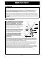
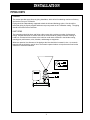
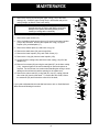
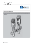
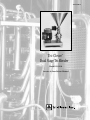
TB-DS-SM-97
Tri-Clover
Dual Stage Tri-Blender
®
Model DS3218
Service & Installation Manual
2
CONTENTS
Thank you for purchasing a Tri-Clover Product!
This manual contains installation, operation, cleaning and repair instructions, with parts lists, for Dual
Stage Tri-Blenders manufactured by Tri-Clover Inc., Kenosha, Wisconsin. It also provides a
troubleshooting chart to assist in determining blender malfunction.
READ THIS MANUAL carefully to learn how to service the Tri-Blender. Failure to do so could result
in personal injury or equipment damage.
SAFETY
IMPORTANT SAFETY INFORMATION .......................................................................................... 4
INTRODUCTION
DESCRIPTION................................................................................................................................ 5
BASIC OPERATION ....................................................................................................................... 5
INSTALLATION
INSTALLATION GUIDELINES ........................................................................................................ 6
PIPING HINTS ................................................................................................................................ 7
MAINTENANCE
CLEANING ...................................................................................................................................... 8
DISASSEMBLY ............................................................................................................................... 8
REASSEMBLY .............................................................................................................................. 11
SETTING THE DRIVE COLLAR AND SEAL REPLACEMENT ..................................................... 15
TROUBLESHOOTING
TROUBLESHOOTING GUIDELINES ........................................................................................... 16
PARTS LIST
MODEL DS3218 ............................................................................................................................ 18
EXPLODED VIEW ........................................................................................................................ 19
3
SAFETY
IMPORTANT SAFETY INFORMATION
Safety is very important!
DO NOT attempt to modify any Tri-Clover product. To do so could create unsafe conditions and
void all warranties. DO NOT place any Tri-Clover product in an application where general
product service ratings are exceeded.
The following DANGER, WARNING, AND CAUTION signs and their meanings are used within these
instructions.
! DANGER
Indicates an imminently hazardous situation which, if not
avoided, will result in death or serious injury. The word
Danger is used in the most extreme cases.
WARNING
Indicates a potentially hazardous situation which, if not
avoided, may result in minor or moderate injury. May
also be used to alert against an unsafe operating or
maintenance practice.
CAUTION
Indicates a potentially hazardous situation which, if not
avoided, could result in death or serious injury.
Safety labels are placed on every Tri-Blender. Do not remove any labeling on any Tri-Clover product.
Immediately replace any label that is missing.
WARNING
ROTATING SHAFT
DO NOT OPERATE
WITHOUT GUARD IN PLACE
Part Number 38-241
4
INTRODUCTION
DESCRIPTION
The Dual Stage Tri-Blender consists of two basic sections, the dry material section and the liquid
material section.
The Dual Stage Tri-Blender is mounted on a base plate. It is mounted adjacent to the drive motor
and is driven by belts running between pulleys under the base plate. The manually controlled
Butterfly valve is standard equipment.
On this model, the connection ends, the diffuser and the suction tube, the inlet adapter, the casing,
screens, washer, the impellers and backplate are made of 316 stainless steel. The hopper is made of
304 stainless steel. All of the tubes are fastened with quick couple Tri-Clamps for easy care and fast
access. The four legs supporting the Tri-Blender are adjustable for easy leveling of the blender during
installation.
BASIC OPERATION
The Tri-Blender basically consists of a centrifugal pump
head and impeller mounted so that the normal suction
port, or inlet, is pointed upward. The inlet piping
consists of a patented tube-within-a-tube arrangement.
This serves to keep the liquid and dry ingredients
separated until they are in the mixing chamber. The
tube-within-a-tube arrangement eliminates prewetting,
one of the major problems of wet-dry mixing.
Our patented (U.S. Patent # 4,850,704) dual stage TriBlender incorporates the proven design characteristics
of our popular Single Stage Tri-Blender, but takes the
concept a step further for even more efficiency.
The Dual Stage concept provides for "double blending."
The product passes through the initial liquid/dry
ingredient blending chamber directly below to a
secondary chamber, which effectively acts as a
discharge pump.
Due to its close proximity, the dual (or second) chamber concept actually increases, rather than
decreases vacuum. The vacuum from the suction of the second pumping stage is added to that of
the first stage, greatly improving product addition rates. The "double blend" feature improves end
product consistency, providing a smoother, more uniform blend.
With the Dual Stage, in applications up to 500 CPS and up to 50 feet (15m) of discharge head, no
discharge pump is required. This is a significant improvement over the Single Stage units, which
normally require an auxiliary discharge pump at 25 feet (7.5m) of discharge head and above. On
some applications with higher CPS, a discharge pump may be necessary.
By incorporating the discharge pump function into the blender itself, you can achieve e significantly
higher vacuum rates over a wider range of process conditions. The increased vacuum provides for
fast, consistent product flow rates with no drop-off through your entire production run.
5
INSTALLATION
INSTALLATION GUIDELINES
UNPACKING EQUIPMENT
When unpacking your equipment, inspect all of the contents for damage that may have occurred
during shipping. Report any damage to the carrier.
LOCATION AND INSTALLATION
The Tri-Blender unit should be located within 3 feet of the liquid source for best performance and in a
position where the supply piping can be short and direct with a minimum number of elbows and
fittings. The liquid to the blender must be supplied by an auxiliary source. It should also be readily
accessible for cleaning and inspection.
The Tri-Blender unit is ready to install as received from the factory. A minimum space of 32" x 47"
(81cm x 119cm) is required. Install the adjustable legs in the base of the unit and position the blender
in the area it will be used. Turn the adjusting leg with a wrench and individually adjust the legs until
the unit is level.
Attach the supply and discharge piping. Be sure that both the inlet and outlet tubes are correctly
positioned and that supply and discharge piping are properly supported to avoid strain on the blender
casing.
The tube OD of the inlet and outlet connections of the blender casing are:
Liquid Inlet
Liquid Outlet
Powder Inlet
1½" (38.1mm)
2" (50.8mm)
3" (76.2mm)
IMPORTANT:
If your blender is equipped with the electrically controlled Butterfly valve,
be sure the valve is wired to an auxiliary 110V power source. The axillary
wiring will let the Butterfly operate independently from the blender motor
and will allow the valve to be closed if the drive motor stops running. If
the auxiliary 110V power source also fails, the Butterfly valve is equipped
with a manual override to close (or open) the valve by applying a suitable
size wrench to the flats on the coupling adapter.
6
INSTALLATION
PIPING HINTS
GENERAL
This section provides some hints on piping installation, which will aid in obtaining maximum efficiency
and service from your Tri-Blender.
Piping should be independently supported at both the inlet and discharge outlet. Care should be
taken that piping is properly aligned and does not put any strain on the Tri-Blender casing. The piping
should have minimum line restriction.
INLET PIPING
The inlet piping should be short and follow a direct route with a minimum number of elbows and
fittings. Elbows should not be used at the inlet as friction would be greatly increased, resulting in
head loss. Excessive friction losses in the inlet line could cause cavitation in the blender casing,
causing poor performance, noise, vibration, and damage to equipment.
Whenever practical, the diameter of the piping at the inlet should be increased in size. An eccentric
tapered reducer should be used in lieu of a concentric tapered reducer to help direct the flow into the
offset tee to minimize turbulence.
7
MAINTENANCE
CLEANING
C.I.P. CLEANING
The Dual Stage Tri-Blender can be cleaned in place. If the Tri-Blender is to be cleaned, the butterfly
valve must be removed and cleaned separately. Refer to separate valve service manual. In addition,
the dry ingredients inlet adapter tube must be capped off.
DISASSEMBLY
GENERAL
The Tri-Blender is relatively maintenance free, requiring normal cleaning and inspection to ensure
optimum performance. Inspect all seals for cuts or abrasions and inspect seal faces for nicks and
cracks. Replace worn or damaged parts as necessary.
REPAIR INFORMATION
Repair of the Tri-Blender is normally accomplished by replacing defective parts. The only moving
parts are the control valve, the impellers, the drive shaft, the seal, the belt, and the motor armature
shaft. It is recommended that all parts of the Tri-Blender be periodically inspected to prevent
malfunctions caused by worn or broken parts. For repair or replacement of the drive motor, refer to
the motor manufacturer. For repair and service of the Butterfly valve on your blender, refer to B
Series Butterfly Valve Service and Installation Manual (B51SM) available from Tri-Clover. Refer to
the parts list for replacement data for the Tri-Blender parts.
TRI-BLENDER DISASSEMBLY
Remove power before
servicing to prevent
unintended start of the
blender.
1
3
WARNING
4
Relieve pressure and
remove all fluid from blender
prior to disassembly.
5
3
4
7
1. Remove the clamp (3) securing the hopper (1) to the blender and remove the
hopper and gasket (4).
8
2. Remove the clamp (3) securing the control valve (5), and remove the valve and
gasket (4). (Hold the valve while loosening the clamp to prevent the valve from
falling.)
9
3. Remove the clamp (8) securing the diffuser and suction tube (7), and remove the
diffuser and suction tube and gasket (9).
9
10
8
4. Remove the clamp (8) securing the inlet adapter (10), and remove the inlet adapter and gasket (9).
8
MAINTENANCE
5. Remove the clamp (22) securing the upper casing (11a) to the lower
casing (11b). Grasp the upper casing firmly in both hands and pull the
casing straight up and off of the lower casing.
IMPORTANT:
Do not use a tool to pry the casings apart. Any object
inserted between the casing and gasket could cause
damage to the gasket and casing sealing surface,
resulting in leakage after reassembly.
11a
22
13
14
15a
6. Remove and inspect the casing o-ring (16).
12
7. Remove the upper screen (12).
17
8. Using a suitable wrench remove the nut (13) securing the upper impeller
(15a) to the stub shaft. Remove the impeller nut o-ring (14), upper
impeller (15a), and backplate (17).
16
9. Remove the diffuser plate (51) and lower o-ring (16).
51
10. Remove the shaft sleeve (54) and o-rings (54a).
54a
54
11. Remove the lower impeller (15b), and lower screen (12).
12. Remove the o-ring (26) from the lower impeller (15b).
54a
12
13. Loosen the three casing bolts, and lift the lower casing (11b) off of the
adapter ring.
15b
14. Remove four screws (66) securing the seal gland (67) to the lower casing
(11b). Inspect all parts of the seal for damage or wear and replace as
required. For the DG seal, use caution when handling the casing to avoid
damage to the surfaces around the opening for the carbon seal.
26
16
11b
15. Remove the carbon seal (25), o-ring seal (26), cup (27), spring (28) and
drive collar (52) from the stub shaft. To remove the drive collar, loosen
the setscrews (53) and lift the drive collar off of the shaft,
68
69
68
If you need to disassemble the stub shaft and motor, refer to Stub Shaft and
Motor Removal following this section.
67
66a
66
25
26
27
28
52
9
53
MAINTENANCE
STUB SHAFT AND MOTOR REMOVAL
Note:
When removing drive components, it is
necessary to tip the entire blender and base
on its side, with the motor end toward the
floor. Remove the hopper, valve, tubing,
casing, impeller, seal guard and seal
components before tipping to make the unit
easier to lift.
1. Loosen the mounting bolts (43) securing the drive
motor (50) to the base (39). (The bolt holes are
elongated to permit belt adjustment.)
2. Slide the motor (50) toward the blender and
remove the drive belts (45).
3. Remove the bolts (44b) securing the blender
pulley (44c). Use the same bolts as a forcing
screw and thread it into the forcing holes, finger
tight.
4. With a suitable wrench, turn the bolt (44b) until
the pulley (44c) releases from the bushing (44a).
Remove the forcing screw and remove the
pulley.
5. Slide tapered bushing (44a) from the shaft (31).
6. Loosen the set screws (53) securing the collar
(30) to the shaft (31) and remove the deflector
collar.
7. Loosen the six capscrews (43) securing the
adapter ring spacers (37). Hold the adapter ring
(23) to prevent it from falling. Remove the
capscrews and remove the adapter and spacers.
8. Set the blender down on its legs (41). Remove
the four capscrews (36) and lockwashers (36a)
securing the bearing housing (34) to the base
(39).
9. Grasp the bearing housing (34) firmly in both
hands and lift it out of the blender base (39).
10. Remove the retaining ring (38) and press the shaft (31) out of the housing (34). Using a suitable
puller, remove the bearing (33) from the shaft and remove the other bearing from the housing.
11. Inspect the shaft (31) sealing surface for nicks or scratches. Inspect all components for cracks
and distortion. Inspect the adjusting legs for worn threads and inspect all o-rings for damage.
12. Replace any worn or damaged components.
IMPORTANT:
The three bearings in the bearing housing are sealed and lifetime lubricated.
If either of the bearings are worn or damaged, make certain they are
replaced with exactly the same type of bearings and replaced as a set.
10
MAINTENANCE
REASSEMBLY
1. Install the o-ring (26) in the deflector collar (30).
2. Install two bearings (33) on the shaft (31) from the bottom until they rests against
the shoulder.
3. Install the shaft into the bearing housing (34).
4. Install the other bearing (33) on the shaft (31) through the bottom of the housing
(34).
5. Install the retaining ring (38) on the bottom of the shaft (31).
6. Install the bearing housing (34) on top of the base (39) and tighten the bolts.
7. Install the deflector (30) on top of the bearing housing (34).
8. Screw the six spacers (37) into the adapter ring (23), and bolt the spacers onto
the baseplate (39).
9. Install the DG insert into the gland ring with gaskets (68).
Note:
If you are using a stainless steel replaceable seat, you won't have
an insert and you'll only use one gasket between the lower casing
and the seat.
10. Install the lower casing (11b) over the shaft (31) and onto the adapter ring.
Use the three casing bolts (11c, shown above) to secure the casing to the
adapter ring.
11. Alternately tighten the spacer bolts (37) to center the shaft (31) in the lower casing (11b).
11
MAINTENANCE
12. Tip the base on its side (39), and install the motor (50).
Tighten the bolts enough so that they contact the
bottom of the base. You’ll use the bolts later to adjust
the belt tension.
13. Install the blender pulley key (44d), pulley (44b), and
bushing (44c) and tighten the bolts (44a). Place the
pulley in position using the correct mounting holes for
the bolts securing the pulley.
14. Install the motor pulley key (46d), pulley (46b), and bushing (46c) and tighten the bolts (46a).
Make sure that both pulleys are horizontally aligned. Draw the pulley tight with the mounting
bolts by alternately tightening each bolt a small amount until all three bolts are tight.
15. Place the drive belt (45) on the motor pulley (46b) and the blender pulley (44b). It may be
necessary to move the motor toward the blender to place the belts on the pulleys. Tighten the
belts by moving the drive motor away from the blender housing until there is a deflection of 5/16"
(7.9 mm) using 5 to 7 pounds of force on the belt. Tighten the motor bolts.
16. Turn the blender upright.
17. Assemble the seal. Refer to Setting the Drive Collar and Seal Replacement section (all motors)
at this point. Then return to Step 17.
18. Slide the lower impeller (15b) with the o-ring onto the shaft (31) and down into the lower casing
(11b).
19. Slide the shaft sleeve (54) with two o-rings (54a) onto the shaft (31).
12
MAINTENANCE
20. Install the upper impeller (15a) onto the shaft (31) with the
impeller nut (13) and o-ring (14).
21. Loosen all spacer bolts (43) to set the clearance between the
lower casing and the lower impeller.
22. Select three alternating adapter ring spacers (37) to adjust for a
.015 to .020 inch clearance between the lower casing and the
lower impeller. Adjust the spacers to obtain a level adjustment.
Tighten the three spacers using the base plate screws (43) to
secure the setting. Recheck the clearance to ensure proper
adjustment.
23. Adjust the three remaining spacers (37) to take up the gap
between the end of the spacer and the base plate. (Also takes up
slack in the threads of the first 3 spacers to prevent casing
movement due to thread clearances.)
24. Tighten the three remaining screws (43) of the spacer to the base plate
connections.
24. Remove the upper impeller (15a).
25. Place the lower screen (12) inside the lower casing (11b) with the pin on the
screen facing upward and lined up with the step in the lower casing.
26. Install the diffuser plate (51) on the lower casing (11b), ensuring that the
pin in the plate fits in the notch in the lower casing. (The pin in the lower
screen must also fit inside the notch on the diffuser plate.)
27. Install the back plate (17).
28. Install the upper impeller (15a) onto the shaft with the impeller nut (13) and o-ring (14).
29. Install the upper screen (12) with the pin down. Rotate the screen counterclockwise until it rests
against one of the tabs on the back plate (17).
13
MAINTENANCE
30. Install the upper casing with o-ring, ensuring that the pins on the upper casing fit into the notches
on the lower casing, and install and tighten the clamp.
31. Install the seal guard (36).
32. Install the inlet adapter (10) on the casing (11),
securing it with a clamp.
IMPORTANT: Be sure to position the adapter (10)
correctly. The adapter inlet should be
opposite the casing outlet (11). See
figure at right.
33. Install the diffuser and suction tube (7) and gasket in
the adapter (10), and secure it with a clamp.
34. Install the butterfly valve (5) and gasket, and secure
it with a clamp (3).
35. Install the hopper (1) and gasket (4) , and secure it
with a clamp (3).
14
MAINTENANCE
SETTING THE DRIVE COLLAR AND SEAL REPLACEMENT
Complete these steps before returning to final reassembly steps in
preceding section.
1. Slide the drive collar and seal assembly toward the seal seat until
the nose of the drive collar pushes the o-ring and carbon seal tight
against the seal seat.
2. Slide the drive collar away from the seal seat 1/32 inch (0.8mm) and
secure the drive collar in this location with the set screws.
3. Remove the impeller screw and the upper impeller.
4. Insert the lower impeller screen with the pin up to align with the hole
in the diffuser.
5. Install the diffuser with an o-ring in the lower casing.
6. Install the backplate onto the diffuser.
7. Insert the upper impeller screen so the pin faces down and when rotated clockwise rests against
one of the 4 tabs of the backplate.
8. Attach the upper impeller to the shaft with the impeller screw and o-ring.
9. Attach the upper casing and o-ring with the large Tri-Clamp to the lower casing while aligning the
backplate tabs with the upper casing grooves.
10. Assemble the remaining tubes and seals securing each section with the proper size clamps.
11. With the blender assembled, and casing clamp tightened, if the drive collar is properly positioned,
and the seal components are properly installed, the blender shaft should rotate freely by hand. If
excessive effort is required to rotate the shaft, check to be sure that all components are properly
installed and the drive collar is properly positioned.
12. Assemble seal guard and tighten nut.
After above setting instructions have been followed, return to the Reassembly section for final steps.
15
TROUBLESHOOTING
TROUBLESHOOTING GUIDELINES
Tri-Blenders are relatively maintenance free with the exception of sanitizing and inspection. Like any
piece of machinery, however, occasional problems can arise. This section provides a means of
determining and correcting most of your Tri-Blender problems. The motor manufacturer should be
contacted for specific repair instructions on the motor.
The chart below has been prepared on the basis that the Tri-Blender, as installed, is properly suited to
its application. Should problems arise where the remedies listed below chart do not cure the situation,
impeller cavitation may be the problem. Symptoms of cavitation, such as noisy operation, insufficient
discharge and vibration, can result when the auxiliary pump or suction tube are not properly applied. If
these conditions are present, check the system and reevaluate the application. If assistance is
required, contact Tri-Clover.
PROBLEM
1. No suction.
PROBABLE CAUSE
REMEDY
a. Wrong supply pump or need of
discharge pump.
a. Verify that pumps are sized correctly to
suit application. Contact Tri-Clover if
you require assistance.
b. Leak on the suction side of the
supply pump or blender.
b. Tighten all clamps, fittings - replace worn
out gaskets.
c.
c.
Carbon seal is worn.
d. Wrong direction of rotation.
Replace carbon seal on blender and/or
supply pump.
d. Reverse a three phase motor by
switching any of the three power leads at
the motor or controller on blender or
supply pump.
e. Inlet port on wrong side.
e. Remove inlet adapter housing and
relocate so it is correctly positioned as
shown on the exploded view pages.
f.
Splashing in the suction throat
of the Tri-Blender.
f.
High Flow - oversized supply pump; see
1a above; see 1e above.
g. High viscosity.
g. See 3b.
h. High temperature.
h. Reduce temperature below 140°F
(60°C).
2. Insufficient
discharge.
a. High viscosity with screen in
casing.
a. Remove screen.
b. No liquids.
b. Check supply pump.
c.
c.
Product too viscous or
discharge head too great.
16
Add discharge pump.
TROUBLESHOOTING
PROBLEM
REMEDY
PROBABLE CAUSE
3. Excessive
power
consumption.
a. High viscosity with screen in
head.
a. Remove screen.
4. Tri-Blender is
noisy.
a. Magnetic hum in motor.
a. Consult motor manufacturer.
b. Motor bearings are worn.
b. Consult motor manufacturer.
c.
c.
b. Install discharge pump on discharge end
of the Tri-Blender.
Tri-Blender bearings are worn.
d. Foreign matter is rotating with
impeller.
Replace bearings.
d. Remove casing and remove foreign
matter - inspect for damage.
Check supply flow to blender.
5. Excessive
vibration.
6. Tri-Blender
leaks.
a. Blender is not leveled properly.
a. Level blender.
b. Impeller is damaged.
b. Replace impeller.
c.
c.
Foreign matter in casing.
Remove casing and remove foreign
matter - inspect for damage.
a. Seal failure.
a. Replace seal.
b. Casing gasket worn or
damaged.
b. Replace gasket.
17
PARTS LIST
MODEL DS3218
All orders for repair parts must contain the following data.
1. Complete model number (located on nameplate).
2. Tri-Blender serial number (located on nameplate).
3. Description and part key number from the parts list.
The exploded views and accompanying parts list facilitate ordering repair parts from the factory. All
parts of the Tri-Blender are exploded and keyed to the parts list.
Key
No. Description
Part Number
Qty
Key
No. Description
Part Number
Qty
1
40° hopper
D3218-55-40-01
1
35 Seal Gaurd
F3218D-131-S
1
2
60° hopper
D3218-55-60-01
1
36 Screw, Bearing Housing
SC1510H-SS
5
3
Clamp
13MHHM-2-S
2
Gasket
40MP-U-2
2
36a Lockwasher, Bearing
Housing
LWA1500-SS
4
5
Manual Butterfly Valve
B51A-4-E-S
1
7
Difuser & Suction Tube
F3218-05-316
1
8
Clamp
13MHHM-4-S
2
9
Gasket
40MP-U-4
2
10 Inlet Adapter
F3218-217-316
DS3218-1B-01-316L
1
11b Lower Casing
DS3218-1A-316L
1
12 Impeller Screen
DS3218-215-316
2
13 Screw, upper impeller
DS3218-26-316L
1
17-15-U
1
15a Upper Impeller
DS3218-2B-02-316
1
15b Lower Impeller
DS3218-2A-02-316
1
16 O-Ring, casing
17 Backplate
22 Clamp, Casing
17-327-U
2
DS3218-11-316
1
DS3218-75-S
DS3218-71-1-S
1
25 Carbon Seal
328E-80-1A-Mat'l
1
26 O-Ring
S328-80-2-U
3
27 Cup
328D-80-3P
1
28 Spring
328D-80-4
1
30 Deflector
31 Drive Shaft
33 Bearings
34 Bearing Housing
F3218-40E-S
1
DS3218-06-316L
1
D3218-18
3
F4329-99-S
1
6
38 Retaining Ring
DS3218-177
1
39 Base Plate
DS3218-23-S
1
01-1154-13-34-U
4
41 Adjustable Leg
R3-1-23-03-S
4
42 Washer, Spacer & Motor
LWA1700-SS
10
43 Screw, Spacer & Motor
SC1712H-SS
10
44 Blender Pulley 50 Cycle
DS3218-106-5-3V5.0x1.500
1
44 Blender Pulley 60 Cycle
DS3218-106-5-3V6.0x1500
1
44d Blender Pulley Key
D3218-46
1
D3218-3VX600
5
46 Motor Pulley 50 Cycle
DS3218-108-5-3V8.0x1.875
1
46 Motor Pulley 60 Cycle
DS3218-108-5-3V8.0x1.875
1
49 Washer, Motor
WA1700-SS
4
51 Diffuser Plate
DS3218-5-316L
1
52 Drive Collar
SP328D-23P-S
1
45 "V" Belt
1
23 Adapter Ring
DS3218-71A-316L
40 O-Ring, Adjustable Leg
1
11a Upper Casing
14 0-Ring, upper impeller
37 Spacer
5
53 Setscrew
SC1105A-SS
1
DS3218-14-316L
4
17-51-U
1
66 Bolt, Gland Ring
SC1310H-SS
2
66a Lockwasher, Gland Ring
LWA1300-SS
4
54 Shaft Sleeve
54a O-Ring, Shaft Sleeve
67 Gland Ring (DG Seal)
SP328G-17-316L
4
67a Stainless Steel Seat
DS3218-17-316L
1
68 PTFE Gasket
SP328G-80-1-2-G
2
SP328G-80-1-1-Mat'l
1
69 Seal Seat
18
EXPLODED VIEW
19
Tri-Clover
manufactures
a complete line of
TRI-WELD® fittings
TRI-CLAMP® fittings
BEVEL SEAT fittings
POSITIVE PUMPS
CENTRIFUGAL PUMPS
AUTOMATIC Air Actuated VALVES
STAINLESS STEEL TUBING
AUTOMATED FLOW CONTROL SYSTEMS
Terms, Warranty Provisions, Notice of Claims and Limitation of Liability
Prices and all terms and conditions of sale are established in
current price sheets and are subject to change without notice. All
orders are subject to acceptance by Tri-Clover Inc. at its Kenosha,
Wisconsin or Distribution Center* offices only. No assignment of
the purchaser’s rights may be made without consent of Tri-Clover
Inc.
Each Tri-Clover item is warranted to be free from manufacturing defects for a period of one (1) year from the date of shipment,
providing it has been used as recommended and in accordance with
recognized piping practice, and providing it has not been worn out
due to severe service, such as encountered under extremely corrosive or abrasive conditions.
This warranty is expressly in lieu of any other warranties,
express or implied, including but not limited to, any implied
warranty of merchantability or fitness for a particular purpose.
All claims must be in writing and must be mailed or delivered
by purchaser within thirty (30) days after purchaser learns of the
facts upon which such claim is based. Any claim not made in writing
and within the time period specified above shall be deemed waived.
Purchaser’s sole and exclusive remedy and Tri-Clover
Inc.’s maximum liability for claims arising hereunder or for
negligence for any and all losses and damages resulting from
any cause shall be either the repair or replacement of defective
items or, at Tri-Clover Inc.’s option, the refund of the purchase
price for such items. In no event, including in the case of a
claim for negligence, shall Tri-Clover be liable for incidental or
consequential damages including loss of profits.
No person, including any representative, employee or agent of
Tri-Clover, is authorized to assume on behalf of Tri-Clover Inc., any
liability or responsibility in addition to or different from that described
in this provision. Any and all representations, promises, warranties
or statements that are in addition to or different from the terms of this
provision are of no force or effect.
*Distribution Centers in Union City, California and St. Charles,
Missouri.
2.5M
TB-DS-SM-97
Printed in Nov 1997