1
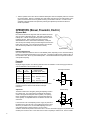
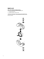
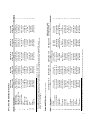
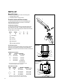
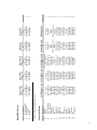
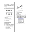
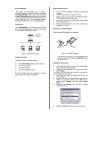
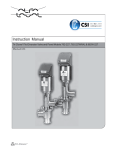
TriClover_ButterflyValve_A51_A52_A53_install_D895
SERVICE MANUAL BFVSM-95
TRI-CLOVER ®
BUTTERFLY VALVE
SERIES A51L • A52 • A53
TABLE OF CONTENTS
INTRODUCTION ............................................................................................................................ 3
SAFETY ......................................................................................................................................... 3
INSTALLATION .............................................................................................................................. 4
REMOVAL AND DISASSEMBLY .................................................................................................... 5
REASSEMBLY AND REINSTALLATION ........................................................................................ 5
OPERATORS ................................................................................................................................. 6
PARTS LIST
A51L / A52 / A53 BUTTERFLY VALVES ........................................................................................ 8
MANUAL A51L SERIES ................................................................................................................. 10
PNEUMATIC ACTUATOR .............................................................................................................. 10
ELECTRIC ACTUATOR ................................................................................................................. 10
SAFETY
Safety is very important!
Included throughout this manual is the safety alert symbol you see to the left.
When you see this symbol be alert to the potential for personal injury.
SIGNAL WORDS: Like DANGER, WARNING, or CAUTION are used with a safety alert symbol.
DANGER-Immediate hazard which WILL result in severe personal injury or death. WARNING-Hazards or
unsafe practices which COULD result in personal injury or death. CAUTION-Hazards or unsafe practices
which COULD result in minor personal injury or product damage.
DO NOT attempt to modify any Tri-Clover product. To do so could create unsafe conditions and void
all warranties. DO NOT place any Tri-Clover product in an application where general product service
ratings are exceeded.
INTRODUCTION
Thank you for purchasing a Tri-Clover Product!
This manual contains disassembly and assembly instructions, maintenance procedures, and complete
parts list for all Series A51L, A52 and A53 Butterfly Valves designed and manufactured by Tri-Clover Inc.,
Kenosha, Wisconsin.
READ THIS MANUAL carefully to learn how to service these valves. Failure to do so could result in
personal injury or equipment damage.
3
INSTALLATION
Pre-Installation Checks
A
For convenience in packaging and storage, the valve is shipped
completely assembled. When installing the valve, it is necessary to
partially disassemble the valve and reassemble it in place.
Verify installation dimensions: Table 1 lists the dimensions required for
assembly of Series A Tri-Flo® Butterfly Valves to a piping run.
Dimension A in Figure 1 is the distance required between fixed
Tri-Clamp® connectors. Refer to Table 2 for the dimensions
required for specific adapters other than Tri-Clamp.
Check pipe-end alignments: If the valve is to be installed
between fixed Tri-Clamp ends, the faces of the Tri-Clamp ends
must be parallel in all planes and on the same centerline.
A
Figure 1
Compressed Seat
Width for All Connectors
Valve Size
Tube O.D.
11/2
IMPORTANT: Failure to have fixed pipe-end openings both
parallel and in alignment will prevent proper sealing of the TriClamp ends to the valve seat gasket. An improperly sealed valve
may leak.
3
/8
2
17
21/2
11
3
13
4
7
/32
/16
/16
1 /64
Table 1
Dimension - Overall Length With Two Connectors Of Same Type
Valve
Size
Tri-Clamp®
Flanged
A51
Flanged
A52 & A53
Female
(NPT)
Male
(NPT)
Butt
Weld
Bevel Seat
Hex Nut ACME
Bevel Seat
ACME End
11/2
25/8
12
51/2
45/8
4 7/8
63/8
6 3/8
313/16
2
325/32
135/8
53/4
419/32
55/32
617/32
617/32
331/32
21/2
315/16
133/4
6
59/16
65/16
611/16
711/16
43/8
3
41/16
14
63/8
63/16
613/16
813/16
85/16
45/8
4
4 /
16 /
6/
6 /
7 /
9/
9/
39 64
1 4
3 8
55 64
31 64
7 64
7 64
551/64
Table 2
Installation Procedure
1. Remove the valve and operator from the shipping package. Inspect for
damage incurred during shipping or storage. Do not attempt to install a
damaged valve.
2. Refer to illustration at right. Using box or socket wrenches of the correct
size, unfasten and remove the hex nuts, screws, and washers, which
fasten the body halves together.
3. Remove the bronze bushings from the seat gasket and butterfly disc
assembly. Inspect each bushing and note that one end is smooth, the other
is grooved. Install the grooved end of each bushing into the body halves.
4. Lubricate the cavities of the body halves and the faces and outer rim of the
seat gasket with Tri-Clover Silicone Spray No. L-1011B.
5. Place the butterfly disc in the open position. Position the seat gasket and
butterfly disc assembly between Tri-Clamp® connectors or Tri-Clamp pipeend adapters, place the body halves (with bushings installed) over the TriClamp flanges, and press together as far as possible.
NOTE: Make sure the bushings are properly located in the body halves.
Make sure the butterfly stem and actuator shaft are properly inserted in the
coupling before proceeding to the next step.
6. Secure the body halves with the screws, washers, lockwasher and nuts.
Tighten the nuts alternately and evenly until the body halves meet. Using box or socket wrenches of
the correct size, tighten the nuts to 30 ft.-lb.
7. Test the operation of the valve. Be sure that the butterfly disc shuts off completely when it is moved to
the closed position. When it is completely shut, both edges of the disc are in the same position on the
gasket, so that the same amount of gasket is showing on both sides of the disc.
4
REMOVAL AND DISASSEMBLY
WARNING: To prevent personal injury, relieve pipe line pressure and drain
all fluids completely
WARNING: To prevent personal injury, disconnect all electrical and
pneumatic power to an operator. The operators actuate with sufficient force
to cause serious injury.
1.
2.
3.
4.
5.
6.
7.
8.
Open the valve to flush and drain the line in which the valve is
located. Close the valve.
Refer to illustration at right. Remove handle clamp bolt and hex nut
from the valve stem and handle. Remove the handle from the stem.
NOTE: It is not necessary to remove a pneumatic or electric operator
to disassemble a valve.
Using box or socket wrenches of the correct size, release and
remove the hex nuts, screws, lockwashers and washers which clamp
the body halves together.
Insert the blade of a screwdriver in the end slot between the body
halves, separate the body halves and release the valve from the TriClamp connectors of pipe-end adapters.
Remove the seat gasket and butterfly disc assembly.
Rotate the butterfly disc to the open position. Squeeze the seat
gasket into an ellipse and remove the bushings.
Refer to illustration below. Squeeze the seat gasket into an ellipse,
raise the butterfly disc and release the lower stem end. The butterfly disc may then be removed.
Inspect all parts for wear or damage. Replace the seat gasket if cracked, worn or deformed. Replace
stem bushings if cracked or worn. Replace butterfly disc if cracked or worn. Replace screw or
nuts if they have stripped or damaged threads.
REASSEMBLY AND REINSTALLATION
WARNING: To prevent personal injury, keep hands and tools away from
butterfly disc when actuating an electric or pneumatic operator. The
operators actuate with sufficient force to cause serious injury.
1.
2.
3.
4.
5.
6.
Refer to illsutration at right. Squeeze the sides of the seat gasket
until it forms an ellipse. Insert the stem of the butterfly disc with the
hex end into the upper hole in the gasket. Locate the lower end of the
stem in the gasket hole. Reshape the gasket and test the action
Disc
of the butterfly disc. The disc should turn freely.
Assembly
Seat
Install the bushings in the body halves with the grooved end of each
bushing into each body half.
Lubricate the cavities of the body halves and the faces and outer rim
of the gasket with Tri-Clover Silicone Spray No. L-1011B.
Place the butterfly disc in the open position. Position the seat gasket
and butterfly disc assembly between Tri-Clamp® connectors or TriClamp pipe-end adapters, place the body halves (with bushings
installed) over the Tri-Clamp flanges, and press together as far as
possible by hand.
NOTE: A normally closed electric or pneumatic operator will have to be opened to put the body halves
together.
NOTE: Make sure the bushings are properly located in the body halves.
Fasten the body halves together with the screws, washers, lockwashers and nuts. Tighten the nuts
alternately and evenly until the body halves meet. Using box or socket wrenches of the correct size,
tighten the nuts to 30 ft-lb.
For the Series A51L-Manual Operator, depress the handle trigger and position the handle on the
butterfly stem. The handle should fit well down over the stem but must clear the top plate. Secure the
handle in place by tightening the clamp screw and the hex nut with wrenches of the correct size.
5
7. Test the operation of the valve. Be sure that the butterfly disc shuts off completely when it is moved to
the closed position. When it is completely shut, both edges of the disc are in the same position on the
gasket, so that the same amount of gasket is showing on both sides of the disc. If it does not shut
completely, adjust the travel of the operator by following the adjustment procedure for either the
electric or pneumatic.
OPERATORS (Manual, Pneumatic, Electric)
Alignment Mark
Each valve should have an alignment mark at the bottom end of the
stem, as shown in illustration at right. This mark is in line with the
butterfly disc. It allows checking the disc position when the valve is
installed in the line. When an older valve without a mark is
disassembled for service, mark it before reassembly. Clamp the
disc securely and carefully make a permanent alignment mark on the
bottom end of the stem. The mark must be exactly in line with the
disc. Be extremely CAREFUL to mark the stem correctly.
Alignment Mark
Manual
Handles and Stop Plates
One of three different handles are used on Tri-Flo Butterfly Vales, depending on size. Note that a locking
handle is now furnished as standard on every size valve. The locking handle permits "position locking" of
the valve disc in OFF, ON or any intermediate position. This standard handle cannot prevent intentional
valve position tampering.
Pneumatic
Installation
80 psig air supply required. The following Solenoid valves are available. Connect air supply to solenoid
valve as illustrated in the schematics to the right.
4/7
110 VAC
Solenoid Selection Chart
4/7
NEMA RATING
220VAC
VOLTAGE (60 HZ. STD.)
33-205-110
33-205-220
3 Way
33-204-110
33-204-220
3 Way - with Flow control
33-183-110
33-183-220
4 Way
33-181-110
33-181-220
4 Way - with Flow control
Normally Closed/Oen
Air
P
C
E
NOTE: Dissembly of the pneumtaic actuator is not recommended.
Contact Tri-Clover for service center location and repair
instructions.
Adjustment
The limits of rotation are changed by setting the adjusting screws in
the cylinder ends. The closing limit is regulated by the adjusting
screw on the right hand side (short end of cylinder). The opening
limit is regulated by the adjusting screw on the left hand side (long
end of cylinder). An adjustable wrench is suitable for the lock nuts
and screws.
Double Acting
P
A
B
E
Loosen the lock nuts on the adjusting screws. Apply air pressure to
the OPEN port to open the valve. If the butterfly disc does not open
all the way or rotates too far, turn the OPEN adjusting screw in or
out to adjust the limit of opening rotation. On air-to-spring
actuators, release the air pressure to close the valve. On air-to-air actuators, apply the air pressure to the
CLOSE port to close the valve. If the valve does not close completely or rotates too far, turn the CLOSE
6
adjusting screw in or out to adjust the closing limit of rotation.
NOTE: Before turning an adjusting screw, operate the actuator in the opposite direction. This will remove
pressure from the adjusting screw so it can be easily turned.
After each adjustment, operate the actuator several times in each direction and recheck the adjustment.
When the adjustments are satisfactory, tighten the lock nuts.
Electric
Installation
A standard wiring diagram is shown to the right.
Disassembly of the Electric Actuator is not
recommended. Contact Tri-Clover for service
center location and repair instructions.
Adjustment
Remove the cover. The limits of rotation are
adjusted by the cams which actuate the mirco
switches. The upper cam controls the closing
limit. The lower cam (closest to valve) controls
the opening limit. Refer to picture below.
1
A.C. LINE
2
3
SPDT
Control
Switch
Or Equal
4
5
Thermal
Overload
Yellow
Brown
NO
Black
NC
Red
CAMS
Blue
NO
1
Field
Wiring
Brake
(Optional)
NC
Actuator
Wiring
2
3
4
5
6
Terminal Strip
To adjust a cam, loosen the set screw in the cam to free it from the shaft, move the cam in the desired
direction, and retighten the set screw. The set screws in all
actuators require 1/16 inch Allen wrench. IMPORTANT: To avoid
stripping threads, tighten set screws firmly, but not excessively.
Connect all wires to the appropriate terminals to open the valve. If
the butterfly disc does not open completely or rotates too far,
disconnect the wires and adjust the OPEN limit cam.
Connect all wires to the appropriate terminals to close the valve. If
the butterfly disc does not close completely or rotates too far,
disconnect the wires and adjust the CLOSE limit cam.
Closing
Limit Cam
Opening
Limit Cam
Set Screw
After each adjustment, operate the actuator several times in each
direction and recheck the adjustment. When the adjustments are satisfactory, install the cover.
IMPORTANT: When installing the cover, be sure the wires are placed where they will not be pinched
between the cover and the internal parts.
7
PARTS LIST
A51L / A52 / A53 Series Butterfly Valves
All orders for repair parts must contain the following data.
1. Complete model number
2. Complete description and part number.
The following exploded view and accompanying parts list facilitate order
repair parts from the factory. All parts illustrated are indexed to the parts
list by key numbers.
10
12
5
9
7
8
9
6
12
13
11
8
9
Description*
Upper Body-A51L
Upper Body-A51RL
Upper Body - A52 / A53
Lower Body-A51L
Lower Body-A51RL
Seat**
Disc A51L / RL
Disc A52 / A53
Bushing
Screw
Nut
Washer
Lockwasher
A51L-2-X-A
A51RL-2-X-A
2"
51-2-01B-01-A
51R-2-01B-01-A
52-2-01B-01-A
51-2-01A-02-A
51R-2-01A-02-A
51-2-42A-X
51-2-05D-316
51-2-05E-316
51-2-08A
SC1316H-SS
NU1300H-E
WA1300-SS
LWA1300-SS
A51L-21/2-X-A
A51RL-21/2-X-A
21/2"
51-21/2-01A-01-A
51R-21/2-01A-01-A
52-21/2-01A-01-A
51-21/2-01-02-A
51R-21/2-01-02-A
51-21/2-42-X
51-21/2-05D-316
51-21/2-05E-316
51-21/2-08
SC1316H-SS
NU1300H-E
WA1300-SS
LWA1300-SS
A51L-3-X-A
A51RL-3-X-A
3"
51-3-01A-01-A
51R-3-01A-01-A
52-3-01A-01-A
51-3-01-02-A
51R-3-01-02-A
51-3-42-X
51-3-05D-316
51-3-05E-316
51-3-08
SC1316H-SS
NU1300-E
WA1300-SS
LWA1300-SS
*
Description*
Actuator
Coupler
Yoke - Upper Half
Yoke - Lower Half
Cap Screw
Lockwasher
Nut
Upper Body
Cap Screw
Cap Screw
Seat
Disc
Lower Body
Bushing
Cap Screw
Washer
Lockwasher
Nut
Lockwasher
52-2-10D-S
52-11/2-47A-01-S
52-11/2-47A-02-S
SC1106H-SS
LWA1100-SS
NU1100H-SS
52-2-01B-01-A
SC1106H-SS
SC906H-SS
51-2-42-X
51-2-05E-316
51-2-01A-02-A
51-2-08A
SC1316H-SS
WA1300-SS
LWA1300-SS
NU1300H-E
LWA900-SS
52-11/2-10D-S
52-11/2-47A-01-S
52-11/2-47A-02-S
SC1106H-SS
LWA1100-SS
NU1100H-SS
52-11/2-01B-01-A
SC1106H-SS
SC906H-SS
51-11/2-42-X
51-11/2-05E-316
51-11/2-01A-02-A
51-11/2-08A
SC1316H-SS
WA1300-SS
LWA1300-SS
NU1300H-E
LWA900-SS
A51L-4- X-A
A51RL-4-X-A
4"
51-4-01B-01-A
51R-4-01B-01-A
51-4-01B-01-A
51-4-01-02-A
51R-4-01-02-A
51-4-42-X
51-4-05D-316
51-4-05E-316
51-4-08
SC1316H-SS
NU1300H-E
WA1300-SS
LWA1300-SS
No. Req'd.
1
1
1
1
1
1
1
1
2
2
2
4
2
A53-P44100-4-X-A N.O.
A53-P2900-21/2-X-A
A53-P2600-3-X-A
A53-P2600-4-X-A N.C.
21/2"
3"
4"
No. Req'd.
Refer to following page
52-21/2-10D-S
52-3-10D-S
52-4-10D-S
1
52-21/2-47A-01-S
52-3-47A-S
52-3-47A-S
1
52-11/2-47A-02-S
None Required
None Required
1
SC1107H-SS
None Required
None Required
2
LWA1100-SS
LWA1100-SS (4 req.) LWA1100-SS (4 req.)
6
None
None
None
2
52-21/2-01A-01-A
52-3-01A-01-A
51-4-01B-01-A
1
SC1107H-SS
SC1106H-SS
SC1107H-SS
4
SC906H-SS
SC1307FF-SS
SC1307FF-SS
4
51-21/2-42-X
51-3-42-X
51-4-42-X
1
51-21/2-05E-316
51-3-05E-316
51-4-05E-316
1
51-21/2-01-02-A
51-3-01-02-A
51-4-01-02-A
1
51-21/2-08
51-3-08
51-4-08
2
SC1316H-SS
SC1316H-SS
SC1316H-SS
2
WA1300-SS
WA1300-SS
WA1300-SS
4
LWA1300-SS
LWA1300-SS
LWA1300-SS
2
NU1300H-E
NU1300H-E
NU1300H-E
2
LWA900-SS
LWA1300-SS
LWA1300-SS
4
All Actuators can be used as normally open or normally closed except 4" which requires a heavier type actuator for noramlly open.
Key #
1
2
3
4
5
6
7
8
9
10
11
12
13
14
15
16
17
18
19
A53-P2400-2-X-A
2"
A53-P2400-11/2-X-A
11/2"
Pneumatic A53 Series (See Following Pages for Drawing)
* A51L = Tube OD, locking handle (std.), or A51RL = Tube OD, recessless ferrule, locking handle.
** "X" as it appears on above charts designates choice of seat material (Item No. &). EDPM is provided as standard- "E" designates EDPM material
Contact Tri-Clvoer for availablity of other seat materials. To avoid confustion when ordering replacemnt parts, please WRITE OUT choice of seat material.
Example: A51L-11/2-E (EPDM)-A
9
10
11
12
13
7
8
6
Key #
5
A51L-11/2-X-A
A51RL-11/2-X-A
11/2"
51-11/2-01B-01-A
51R-11/2-01B-01-A
52-11/2-01B-01-A
51-11/2-01A-02-A
51R-11/2-01A-02A
51-11/2-42A-X
51-11/2-05D-316
51-11/2-05E-316
51-11/2-08A
SC1316H-SS
NU1300H-E
WA1300-SS
LWA1300-SS
A51L / A52 / A53 Series Butterfly Valves
PARTS LIST
Manual A51L Series
All orders for repair parts must contain the following data:
1. Complete model number.
2. Complete description and part number.
Manual
2
Pneumatic Actuator and Electric Actuator
To order replacement parts for the Tri-Clover Butterfly with
Pneumatic Actuator and Electric Actuator, include all the
information asked for below:
1
Valve Replacement Parts
To order valve replacement parts, the valve part number must
be included with your order. To obtain the part number of the
valve you have, refer to the sample part number below and build
the part number of your valve.
A53A
- P2200 -
3
1
2
3
1
Valve Series
2
Actuator
3
Valve Size
4
Seat Material
-
E
-
A
4
5
4
3
5 External Body Material
Actuator Replacement
There are no model or serial numbers on the actuator, therefore
obtain the correct actuator part number from the table below
knowing the valve size and for the Electric Actuators, the actuator
voltage.
Electric
1
2
5
18
PNEUMATIC ACTUATOR
Valve
Size
16
Actuator Part Number
Air to Air
Air to Spring
11/2", 2"
A53A-P2000
53-P2400
21/2"
A53A-P2100
53-P2500
3"
A53A-P2200
53-P2600
4"
A53A-P2200
53-P2600-NC*
Pneumatic
53-P44100-NO*
* All pneumatic actuators can be used normally open (NO)
or normally closed (NC) except 4" size above.
ELECTRIC ACTUATOR
Valve
Actuator
Actuator Part Number
Size
Voltage
Waterproof
Explosion Proof
11/2"
120
A52-E7000B
A52-E7000B
2"
220
A52-E7100B
A52-E7100B
21/2", 3"
120
A52-E2800B
A52-E3000B
4"
220
A52-E2900B
A52-E3100B
Actuator for 1 1/ 2 and 2" sizes varies in appearance from
larger sizes-housing is semi-round, rather than retangular.
10
6
15
19
12
10
See Previous Page for
Parts List
1
5
16
12
10
15
6
2
18
19
11
Description*
Handle Assembly
Handle Sleeve
Stop Plate
Screw
A51L-11/2-X-A
A51RL-11/2-X-A
11/2"
51L-11/2-48G-S
51-11/2-48G-06-35A
51-11/2-86D-S
SC1005D-SS
Key #
1
2
3
4
5
6
7
8
9
10
11
12
13
14
15
16
17
18
19
Description*
Actuator
Coupler
Yoke - Upper Half
Yoke - Lower Half
Cap Screw
Lockwasher
Nut
Upper Body
Cap Screw
Cap Screw
Seat
Disc
Lower Body
Bushing
Cap Screw
Washer
Lockwasher
Nut
Lockwasher
Electric A52 Series
A52-E7XXXB-2-X-A
2"
52-2-10D-S
52-11/2-47A-01-S
52-11/2-47A-02-S
SC1106H-SS
LWA1100-SS
NU1100H-SS
52-2-01B-01-A
SC1106H-SS
SC907H-SS
51-2-42A-X
51-2-05E-316
51-2-01A-02-A
51-2-08A
SC1316H-SS
WA1300-SS
LWA1300-SS
NU1300H-E
LWA900-SS
52-11/2-10D-S
52-11/2-47A-01-S
52-11/2-47A-02-S
SC1106H-SS
LWA1100-SS
NU1100H-SS
52-11/2-01B-01-A
SC1106H-SS
SC907H-SS
51-11/2-42A-X
51-11/2-05E-316
51-11/2-01A-02-A
51-11/2-08A
SC1316H-SS
WA1300-SS
LWA1300-SS
NU1300H-E
LWA900-SS
A51L-2-X-A
A51RL-2-X-A
2"
51L-2-48G-S
51-2-48G-06-35A
51-11/2-86D-S
SC1105D-SS
A52-E7XXXB-11/2-X-A
11/2"
or A51RL = Tube OD, recessless, locking handle.
* A51L = Tube OD, locking handle (std.),
Key #
1
2
3
4
Manual A51L Series
A51L-3-X-A
A51RL-3-X-A
3"
51L-3-48G-S
51-2-48G-06-35A
51-11/2-86D-S
SC1105D-SS
A52-EXXXXB-21/2-X-A A52-EXXXXB-3-X-A
21/2"
3"
Refer to previous page
52-21/2-10D-S
52-3-10D-S
52-21/2-47A-01-S
52-3-47A-S
52-11/2-47A-02-S
None
SC1107H-SS
None
LWA1100-SS
LWA1100-SS (4 req.)
None
None
52-21/2-01A-01-A
52-3-01A-01-A
SC1107H-SS
SC1106H-SS
SC907H-SS
SC1307FF-SS
51-21/2-42-X
51-3-42-X
51-21/2-05E-316
51-3-05-316
51-21/2-01-02-A
51-3-01-02-A
51-21/2-08
51-3-08
SC1316H-SS
SC1316H-SS
WA1300-SS
WA1300-SS
LWA1300-SS
LWA1300-SS
NU1300H-E
NU1300H-E
LWA900-SS
LWA1300-SS
A51L-21/2-X-A
A51RL-21/2-X-A
21/2"
51L-2-48G-S
51-2-48G-06-35A
51-11/2-86D-S
SC1105D-SS
52-4-10D-S
52-3-47A-S
None
None
LWA1100-SS (4 req.)
None
51-4-01B-01-A
SC1107H-SS
SC1307FF-SS
51-4-42-X
51-4-05E-316
51-4-01-02-A
51-4-08
SC1316H-SS
WA1300-SS
LWA1300-SS
NU1300H-E
LWA1300-SS
A52-EXXXX-4-X-A
4"
A51L-4-X-A
A51RL-4-X-A
4"
51L-4-48G-S
51-4-48G-06-35A
51-4-86C-S
SC1105D-SS
1
1
1
2
6
2
1
4
4
1
1
1
2
2
4
2
2
4
No. Req'd.
No. Req'd.
1
1
1
4
Tri-Clover
manufactures
a complete line of
TRI-WELD ® fittings
TRI-CLAMP® fittings
BEVEL SEAT fittings
POSITIVE PUMPS
CENTRIFUGAL PUMPS
AUTOMATIC Air Actuated VALVES
STAINLESS STEEL TUBING
AUTOMATED FLOW CONTROL SYSTEMS
Terms, Warranty Provisions, Notice of Claims and Limitation of Liability
Prices and all terms and conditions of sale are established in
current price sheets and are subject to change without notice. All
orders are subject to acceptance by Tri-Clover Inc. at its Kenosha,
Wisconsin or Distribution Center* offices only. No assignment of
the purchaser’s rights may be made without consent of Tri-Clover
Inc.
Each Tri-Clover item is warranted to be free from manufacturing defects for a period of one (1) year from the date of shipment,
providing it has been used as recommended and in accordance with
recognized piping practice, and providing it has not been worn out
due to severe service, such as encountered under extremely corrosive or abrasive conditions.
This warranty is expressly in lieu of any other warranties,
express or implied, including but not limited to, any implied
warranty of merchantability or fitness for a particular purpose.
All claims must be in writing and must be mailed or delivered
by purchaser within thirty (30) days after purchaser learns of the
facts upon which such claim is based. Any claim not made in writing
and within the time period specified above shall be deemed waived.
Purchaser’s sole and exclusive remedy and Tri-Clover
Inc.’s maximum liability for claims arising hereunder or for
negligence for any and all losses and damages resulting from
any cause shall be either the repair or replacement of defective
items or, at Tri-Clover Inc.’s option, the refund of the purchase
price for such items. In no event, including in the case of a
claim for negligence, shall Tri-Clover be liable for incidental or
consequential damages including loss of profits.
No person, including any representative, employee or agent of
Tri-Clover, is authorized to assume on behalf of Tri-Clover Inc., any
liability or responsibility in addition to or different from that described
in this provision. Any and all representations, promises, warranties
or statements that are in addition to or different from the terms of this
provision are of no force or effect.
*Distribution Centers in Union City, California and Memphis,
Tennessee
BFVSM-95
Printed in August 1995