1
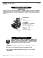
Operator’s Manual NHP (Small) Series Gas READ THIS MANUAL This manual contains important information for the use and safe operation of your Amazing Machinery™ machine. FAILURE TO READ THIS MANUAL AND FOLLOW ITS INSTRUCTIONS PRIOR TO OPERATING OR ATTEMPTING ANY SERVICE OR MAINTENANCE PROCEDURE COULD RESULT IN SERIOUS INJURY OR DEATH TO YOU OR OTHER PERSONS; ALSO DAMAGE TO THE MACHINE OR TO OTHER PROPERTY. AMAZING MACHINERY Amazing Machinery 3807 OLD TASSO 1 4 2 7RD. 5 NNE o rt hC CLEVELAND, TN 37312 Phone: 1-800-504-7435 Fax: 1-800-504-7436 ® 405 Operator’s Manual Page TABLE OF CONTENTS SECTION 1 OPERATOR’S MANUAL Unpacking Safety Instructions and Warnings Installation Instructions Operation Instructions Starting Checklist Washing Techniques Stopping Machine Moving, Storage and Winterizing Maintenance Instructions Engine Maintenance Pump Maintenance Heat Exchanger Coil Coil Descaling Electrode Settings Unloader Adjustment Oil Burner Air Band Adjustment SECTION 2 PARTS AND SERVICE MANUAL 3 3 5 6 6 7 7 7 8 8 8 8 8 9 10 10 11 11 12 13 14 15 16-17 18-19 20-21 22-23 Exploded Assembly View (NHP Series) Parts List Gun and Wand Assembly Burner Assembly Pump Assembly Control Box Wiring Diagrams Pump and Related Plumbing Diagrams Troubleshooting Warranty NOTICE Information in this operator’s manual is subject to change without notice. Amazing Machinery INCORPORATED SHALL NOT BE LIABLE FOR TECHNICAL OR EDITORIAL ERRORS OR OMISSIONS CONTAINED HEREIN. This operator’s manual contains information protected by copyright. No part of this operator’s manual may be photocopied or reproduced in any form without prior written consent from Amazing Machinery Incorporated. © Amazing Machinery All rights reserved. Printed in USA. First Printing (February 2005) AMAZING MACHINERY 3807 OLD TASSO RD. NE CLEVELAND, TN 37312 Phone: 1-800-504-7435 Fax: 1-800-504-7436 Operator’s Manual Page UNPACKING INSTRUCTIONS INSPECTION Carefully unpack your new Amazing Machinery™ pressure washer by removing the banding and cardboard box from pallet. Remove the pressure washer from the pallet and check for any physical damages that may have occurred during shipment. Check for all parts specified and shown in figure 1. Included Parts • • • • • • • • • Pallet Packing Material Outer Box Machine NHP Small Series Wand / Trigger Gun Nozzle 0º, 15º, 25º, 40º Hose 3/8” X 50’ Manual QC Hose Fittings Figure 1 SAFETY INSTRUCTIONS � WARNING READ THIS FIRST! Failure to read and observe all WARNING statements could result in severe bodily injury or death, possible injury to other persons, damage to machine or other property. This machine should not be operated in areas where open flames are not permitted. Do not store or use combustible materials on or near this machine. Do not operate this machine while under the influence of alcohol, drugs or while fatigued. AMAZING MACHINERY 3807 OLD TASSO RD. NE CLEVELAND, TN 37312 Phone: 1-800-504-7435 Fax: 1-800-504-7436 Operator’s Manual Page SAFETY INSTRUCTIONS Do not direct discharge stream at yourself or others. Risk of injection or injury may occur. This product should only be operated by trained personnel. Do not operate this machine without wearing protective eye wear. Do not tie back or block trigger gun in OPEN position. Do not operate this machine in areas with poor or no ventilation. This machine requires air for combustion and flue gas evacuation. See specifications for required volume for your model. Do not overreach or stand on an unstable support while operating this machine. Maintain good footing and balance. Do not permit this machine to run while unattended or for extended periods of time with trigger gun closed. Damage to pump may occur. Do not operate this machine in an unsafe manner or around unsupervised children. Keep all other personnel clear while operating this machine. Do not service this machine without disconnecting power supply and shutting off gas source. This machine is equipped with a manual shutoff valve. Do not alter original factory settings prior to operating this machine. Risk of injury to yourself or other persons may occur. Do not remove hoses, guns, nozzles or any components while this machine is still hot or while it is running. Do not operate machine with service covers removed. Do not attempt to service this machine before reading the service manual. Do not operate this machine without knowing how to stop and bleed water pressures. Know all controls before using this machine. Do not spray caustic, acids or abrasive fluids through this machine. Do not permit lime and scale buildup to occur in the heat exchanger coil. Do not permit water to freeze inside this machine. Risk of coil, pump and plumbing damage may occur. Use only recommended Amazing Machinery™ parts when servicing this machine. Amazing Machinery™ will not be held liable for any unauthorized modifications made to this machine. AMAZING MACHINERY 3807 OLD TASSO RD. NE CLEVELAND, TN 37312 Phone: 1-800-504-7435 Fax: 1-800-504-7436 Operator’s Manual Page installation INSTRUCTIONS � WARNING FILL FUEL TANKS IN OPEN AREA AWAY FROM OPEN FLAMES OR SPARKS. USE ONLY CLEAN FUEL VOID OF WATER AND CONTAMINATES. Following the requirements below will insure a successful installation. Install group 24, 750- 850 cold cranking amp battery. Red cable is attached to positive terminal. Check fuel oil and fill with diesel #1, diesel #2, kerosene or #1 home heating oil. Check the gasoline tank and fill with a good grade of gasoline. Check the engine oil level and fill with SAE 10W40 if needed. Check the pump oil level and fill with SAE 30w non-detergent oil if needed. Connect water hose to the water inlet connection located on the machine. Turn on water and check float tank for water level. Start gas engine and continue until water discharges from coil Stop engine and connect high pressure hose to the outlet. Restart engine and open trigger gun control to flush system until water is clear. Install water nozzle at the end of wand, making sure it is clear of any obstructions. Turn burner switch to “ON” position and check for burner ignition. Check for leaks in the system and cycle trigger gun to insure bypass is adjusted correctly. Repair and leaks nad correct unloader adjustment if needed. If unit is hot, run until unit is cool then shut down machine. AMAZING MACHINERY 3807 OLD TASSO RD. NE CLEVELAND, TN 37312 Phone: 1-800-504-7435 Fax: 1-800-504-7436 Operator’s Manual Page OPERATING INSTRUCTIONS � MAKE SURE ALL SWITCHES ARE IN THE OFF POSITION BEFORE STARTING MACHINE. WARNING STARTING THE MACHINE Read this manual before starting this machine. Protective eye wear and clothing is required during operation of this machine. Check pump oil level: If needed add SAE 30 weight non-detergent oil. Connect water supply hose to unit, do not turn water on. Check all fluid levels. a) Pump Oil: If needed add SAE30 w non-detergent oil. b) Fuel Oil Tank: Use only kerosene,diesel #1 or #2 or #1 home heating oil. c) Fuel Gasoline: Use a good grade of gasoline. Quick connect the 50ft. discharge hose and gun assembly to outlet of heater coil, and remove pressure nozzle from end of wand. Turn on water supply, and open trigger gun. DO NOT START ENGINE WITH BURNER SWITCH ON. Start gas engine and allow RPM to develop. SMALL ENGINES MAY KICK BACK. DO NOT HOLD PULL CORD TOO TIGHTLY. Turn burner switch “ON” and open the trigger gun while firmly gripping the wand assembly. Grasp the grip on the wand with one hand and the trigger gun with the other. Do not touch unprotected HOT surfaces with bare hands. Insert detergent siphoning tube into a DOT approved container and open the metering valve for detergent application. AMAZING MACHINERY 3807 OLD TASSO RD. NE CLEVELAND, TN 37312 Phone: 1-800-504-7435 Fax: 1-800-504-7436 Operator’s Manual Page OPERATING INSTRUCTIONS � WARNING DO NOT STORE COMBUSTIBLE MATERIALS (GASOLINE, DIESEL OR OTHER PETROLEUM PRODUCTS) NEAR PRESSURE WASHER WHILE OPERATING. WASHING TECHNIQUES Water spray should be hot and soapy prior to washing. Washing from bottom up increases dwell time of soap and lessens vertical streaks. Turn soap metering valve and burner switch “OFF” to purge system of soap and hot water. Rinsing with cold water from top down will retard detergent reaction which will enhance the rinsing performance. Wash at 30 to 60 degree angles to prevent splashback. STOPPING THE MACHINE Turn burner motor switch “OFF” and continue allowing water to discharge while cooling down. Turn engine off and discharge water pressure from trigger gun. Turn water supply “OFF”. Place wand in holder and coil up pressure hose or wind up on hose reel. MOVING, STORAGE Protect machine from freezing temperatures by storing in heated area. WINTERIZING Direct Drive Machines: To protect the machine from freezing temperatures while storing or transporting, connect short length of garden hose (approximately 3 ft.) to water inlet connection on machine. Remove the pressure nozzle from the wand and insert the short garden hose end into a container of antifreeze. Place the wand into the antifreeze container and start engine running machine until antifreeze appears from the end of the wand. Turn engine “OFF” and replace pressure nozzle. Coil up hose and move machine to storage area. Float Tank Machines: Pour antifreeze into float tank and remove water nozzle from end of wand and carefully insert into opening of float tank. Start machine and run until antifreeze water mixture has circulated throughout the machine returning back to the float tank. AMAZING MACHINERY 3807 OLD TASSO RD. NE CLEVELAND, TN 37312 Phone: 1-800-504-7435 Fax: 1-800-504-7436 Operator’s Manual Page MAINTENANCE INSTRUCTIONS � WARNING FAILURE TO MAINTAIN HEAT EXCHANGER COIL MAY RESULT IN A STEAM EXPLOSION WHICH MAY CAUSE SERIOUS INJURY OR DEATH. ENGINE MAINTENANCE First 8 hours: Every 8 hours: Every 25 hours: Change oil. Check oil level. Change oil if operating under heavy load or high ambient temperature. Service air cleaner pre-cleaner. Every 50 hours: Change oil. Clean and inspect spark arrester if equipped. Every 100 hours: Service air cleaner cartridge, replace oil filter (if equipped), Clean oil cooler (if equipped), Clean cooling system. PUMP MAINTENANCE Fill crankcase to dot on oil gauge window per specifications with 30W Nondetergent Oil. Change oil after 40 Hour Break-in Period. Change oil every Three Months or at 500 Hour Intervals thereafter. HEAT EXCHANGER COILS Hard water conditions may eventually cause clogging in the heat exchanger. If so it may be necessary to descale coil, since scale deposits will compromise the heating efficiency and produce an unsafe condition. Scale buildup from certain detergents may eventually clog up the heat exchanger coil causing an unsafe condition. Use only Amazing Machinery™ recommended detergents for better cleaning efficiency. COIL DESCALING: Mix in a 5 gallon pail, one pound of deliming powder for every gallon of water used. Attach one end of a 4-6 foot length of rubber hose to the water intake connector and insert the other end into the thoroughly mixed deliming solution. Remove the trigger gun from the high pressure hose and place the hose end into the mixed deliming solution. Turn pump motor switch “ON”, allowing even water flow from the pickup hose in the deliming solution through the pump, plumbing, coil and hose, returning back to the solution container. DO NOT TURN THE BURNER ON. Continue to circulate solution for as long as it takes to clear the build-up (may require multiple treatments). Re-install the trigger gun. Flush the system with clean water. AMAZING MACHINERY 3807 OLD TASSO RD. NE CLEVELAND, TN 37312 Phone: 1-800-504-7435 Fax: 1-800-504-7436 Operator’s Manual Page MAINTENANCE INSTRUCTIONS ELECTRODE SETTINGS Inspection of all wires, spring contacts and electrodes should be done periodically. See figure 2. Figure 2 � USE INSULATED SCREWDRIVER WHEN CHECKING TRANSFORMER. WARNING Proper electrode setting should be done with a defect-free insulated screwdriver across one contact. Settings are correct when arc spans 1/2” between the end of the screwdriver blade and the other contact. See figure 3. AMAZING MACHINERY Figure 3 3807 OLD TASSO RD. NE CLEVELAND, TN 37312 Phone: 1-800-504-7435 Fax: 1-800-504-7436 Operator’s Manual Page 10 MAINTENANCE INSTRUCTIONS UNLOADER ADJUSTMENT Turn adjusting knob to the lowest spring tension (counterclockwise) and start machine. Open trigger gun and begin adjustment of pressure by turning adjusting nut (clockwise) until machine is at normal operating pressure. Open and close the trigger gun to set unloader and check for high spike pressures. Turn the adjusting nut (counterclockwise), decreasing pressure slightly. Replace lock nut, adjusting it down to lock the adjusting nut to shaft. See figure 4. OIL BURNER AIR BAND ADJUSTMENT Figure 4 ® Amazing Machinery sets oil burners at sea level. Air bands may need adjustment at higher elevations to offer enhanced performance of the burner and extended life of the machine. � WARNING IF BLACK OR WHITE SMOKE VENTS FROM EXHAUST PORT UPON STARTING EQUIPMENT, DISCONTINUE USE AND ADJUST AIR BANDS BEFORE RESTARTING. Adjustment of burner is done with pump motor and burner switches “ON”. Loosen locking screw on air band, then close band until black smoke vents up exhaust vent. Take careful note of air band position when black smoke is first noticed. Slowly open air band until white smoke vents, then turn air band halfway back to where black smoke was first noted. Tighten air band locking screw. See figure 5. AMAZING MACHINERY Figure 5 3807 OLD TASSO RD. NE CLEVELAND, TN 37312 Phone: 1-800-504-7435 Fax: 1-800-504-7436 Operator’s Manual Page 11 Chassis Components Part # Description 180-00300-01 Chassis,NHP small Series 180-00308-01 Handle,NHP small series (round tubing) 175-00001-04 Axle,SS,5/8"x28.5", NHP small 567-00016-01 Spacer,nylon,.812 OD x .63 ID x .220"thk 516-00001-01 Bushing,Wheel Collar,5/8" 170-00007-01 Wheel,pneu,12",tubetype,1 pc hub,5/8 brg 190-00002-01 Tank,fuel,9 gal,green ID0104 530-00002-02 Elbow,brs,1/4nptm x 1/4 barb,90degr 140-00001-01 Cap,fuel guage,diesel,black 180-00287-01 Power Plate,XV Series, Electric 505-00006-03 Bolt,SS,Carriage,3/8-16x1" 508-00007-02 Pushnut,SP,5/16 522-00001-01 Conn,hose end,1/4nptm x 1/4 barb 280-00003-01 Fuel line,1/4"ID x 3/8"OD,Black 280-00003-01 Fuel line,1/4"ID x 3/8"OD,Black AMAZING MACHINERY Qty. 1EA 1EA 2EA 4EA 4EA 4EA 1EA 2EA 1EA 1EA 3EA 3EA 2EA 12IN 12IN 3807 OLD TASSO RD. NE CLEVELAND, TN 37312 Phone: 1-800-504-7435 Fax: 1-800-504-7436 Operator’s Manual Page 12 Trigger Gun, Wand and Hose 6 Dual Lance Wand Down Stream injection 7 8 4 5 1 2 3 Figure 7 Ref.# 1d 1e 1f 1g 2 3 4 5 Part # 270-00002-01 270-00002-02 270-00002-03 270-00002-04 265-00001-01 275-00001-01 552-00004-03 284-00001-01 Description Nozzle 4.0 x 0º x 1/4” Nozzle 4.0 x 15º x 1/4” Nozzle 4.0 x 25º x 1/4” Nozzle 4.0 x 40º x 1/4” 36” Wand, Insulated (optional) ST1500 Trigger Gun 3/8” nptm Quick Connect Plug Hose 3/8” X 50’ R-1 Swivel Ends Qty. 1 1 1 1 1 1 1 1 Dual Lance Wand (Standard) 6 7 8 AMAZING MACHINERY 554-00006-02 1/4” nptm Quick Connect Socket 270-00038-01 Nozzle (Low Pressure Soap) #40, 15° 265-00002-01 Dual Lance Wand 3807 OLD TASSO RD. NE CLEVELAND, TN 37312 Phone: 1-800-504-7435 Fax: 1-800-504-7436 1 1 1 Operator’s Manual Page 13 12 Volt Burner Assembly 5 3 3a 7 6 8 4 9 2 10 1 11 Figure 8 Ref# Part # 1 260-00004-01 2 256-00001-02 3 254-00001-04 3a 4 253-00002-01 5 252-00001-04 6 253-00001-01 7 251-00001-01 8 259-00001-01 8a 259-00001-02 9 258-00002-03 10 245-00012-14 11 577-00002-01 Description Air Cone Main Burner Gasket Motor, 12v DC, Fasco Motor, Flange Fan Wheel, 3.44” X 4.25” Ignitor Coupling Fuel Pump Air Band Inner Air Band Outer Electrodes Nozzle,Fuel Filter, Racore Qty 1 1 1 1 1 1 1 1 1 1 1pr 1 1 Burner Assembly Complete 250-00005-01 MSR-DC Wayne 12 volt Burner AMAZING MACHINERY 3807 OLD TASSO RD. NE CLEVELAND, TN 37312 Phone: 1-800-504-7435 Fax: 1-800-504-7436 Operator’s Manual Page 14 NHP small SERIES PUMP Comet Pump LWD3025G Hollow Shaft Triplex Pump 1 2 Figure 9 Ref.# Part # Description 1 220-00096-01 Comet LWD3025G Triplex Plunger Pump Complete (7hp) non-stock Manifold, Brass Head #3218.0108.00 2 Qty 1 1 Pump Repair Kits Part # 221-00310-02 221-00315-03 221-00309-01 221-00306-01 221-00301-01 221-00302-01 AMAZING MACHINERY Description Qty Check Valve Assembly Kit, 1 kit required Oil Seals, sold per each, 3 required Brass Valve Cap, sold per each, 6 required Valve Cap O-ring, sold per each, 6 required Brass Packing Retainer, sold per each, 3 required Packing Kit (brass not included), 1 kit required 1 kit 3 6 6 3 1 kit 3807 OLD TASSO RD. NE CLEVELAND, TN 37312 Phone: 1-800-504-7435 Fax: 1-800-504-7436 Operator’s Manual Page 15 NHP small CONTROL BOX PARTS LIST 4 1 2 3 Figure 10 Ref.# Part # 1 2 3 4 450-00001-01 571-00002-01 305-00040-01 573-00001-01 AMAZING MACHINERY Description Qty Rocker Switch Hourmeter Label, Controls Thermostat Assembly 1 1 1 1 3807 OLD TASSO RD. NE CLEVELAND, TN 37312 Phone: 1-800-504-7435 Fax: 1-800-504-7436 Operator’s Manual AMAZING MACHINERY 3807 OLD TASSO RD. NE CLEVELAND, TN 37312 Phone: 1-800-504-7435 Fax: 1-800-504-7436 Page 16 Operator’s Manual Page 17 BURNER MODULE “Small” BLK RED WHT BLK BLOWER “Big” RED IGNITOR XFMR yellow - N.O. + yellow White BLK Orange FUEL SOLENOID DROPOUT TIMER yellow Photocell “Small” RED BLK RED WHT BLK CONTROL PANEL RED AC + BURNER SW WHT - AC RED BLK RED BLK WHT TYPICAL SCHEMATIC BLK 87 WHT 86 85 1 30 P1 THERMOSTAT RED RED BRN RED RED GRN WHT BLK FLOW SW or PRESSURE SW BATTERY STARTER SOLENOID BLK ALTERNATOR 12 VOLT Electrical Schematic AMAZING MACHINERY GAS ENGINE 3807 OLD TASSO RD. NE CLEVELAND, TN 37312 Phone: 1-800-504-7435 Fax: 1-800-504-7436 1 4 2 75 NW FRE E WAY P H O N E : 71 3 . 9 8 3 . 6 0 0 0 H O U S T O N, TX 77 0 4 0 FA X: 71 3 . 9 8 3 . 6 4 05 Operator’s Manual Page 18 NHP small PLUMBING DIAGRAM - NO FLOAT RELIEF VALVE, AV150 & AV230 JE ADAMS 7415 (1500 PSI) 569-00003-01 RELIEF VALVE, AV200 & AV300 JE ADAMS 7416 (2000 PSI) 569-00003-02 NIPPLE, GALVANIZED STEEL 1/2 NPT X 2.5" QUICK CONNECT COUPLER 3/8 NPTM X 3/8 MALE Upgrade Plumbing AV150 AV200 AV230 AV300 MANIFOLD THERMOSTAT HOSE END, HIGH PRESSURE 3/8 NPTM SWIVEL X 3/8 HOSE HIGH PRESSURE HOSE 3/8 I.D. X 13" ELBOW, PLATED STEEL 3/8 NPT STREET HOSE END, SWIVEL #8 JIC FEMALE X 3/8 BARB HOSE END, HIGH PRESSURE 3/8 NPTM SWIVEL X 3/8 HOSE BUSHING, PLATED STEEL 3/8 NPT X 1/4 NPT PRESSURE SWITCH TEE, PLATED STEEL 1/4 NPT, STREET ELBOW, BRASS 3/8 NPTM X #8 FLARE LOW PRESSURE HOSE 3/8 I.D. X 13" HOSE END, SWIVEL #8 JIC FEMALE X 3/8 BARB CLAMP BAND (5 PL.) Ø1/4 - 5/8 HOSE END, SWIVEL #8 JIC FEMALE X 3/8 BARB CONNECTOR, BRASS 3/8 BARB X 3/8 NPTM ELBOW POLYPROPYLENE 3/8 BARB X 3/8 BARB COUPLER, UNIVERSAL 3/8 NPTF X 3/8 NPTF ELBOW, PLATED STEEL 3/8 NPTF X 1/2 NPTF NIPPLE, GALVANIZED STEEL 1/2 NPT X 2.5" 185-00001-01 569-00003-01 569-00003-02 569-00003-03 280-00002-02 574-00002-01 230-00007-01 284-00010-04 430-00013-01 570-00002-01 285-00002-01 577-00001-01 281-00002-03 579-00001-01 528-00002-03 536-00003-01 ELBOW, BRASS 1/4 NPTM X #4 FLARE CONNECTOR, BRASS 3/8 BARB X 3/8 NPTM 1/2 NPT PLUG TEE, PLATED STEEL 3/8 NPT BRANCH HOSE END, SWIVEL #4 JIC FEMALE X 1/4 BARB LOW PRESSURE HOSE 1/4 I.D. X 16" LOW PRESSURE HOSE 3/8 I.D. X 10.5" GARDEN HOSE CONNECTOR 3/4 SWIVEL X 3/8 NPTM ELBOW, BRASS 1/4 NPTM X 1/4 BARB Ref.#Part # PUMP TEE, BRASS 3/8 NPT, STREET TO COIL INLET AMAZING MACHINERY NIPPLE, PLATED STEEL 1/4 NPT CLOSE HEX ELBOW, PLATED STEEL 1/4 NPT, STREET BULKHEAD FITTING 1/2 NPTF I.D. 1 2 2a 2b 3 4 5 6 7 8 9 10 11 12 13 3/8 NPT PLUG 1/4 NPT PLUG CONNECTOR, BRASS #8 FLARE X 1/2 NPTM 554-00005-01 FLOAT TANK ELBOW, BRASS #8 FLARE X 1/4 NPTM 3/8 NPT PLUG UNLOADER SUTTNER ST-280 LOW PRESSURE HOSE 3/8 I.D. X 35" METER VALVE DETERGENT LINE 1/4" I.D. TUBE X 50" ELBOW, BRASS 1/4 NPTM X 1/4 BARB Figure 11 Description Manifold, Coil Outlet Pressure Relief Valve 1500 PSI (AV 150) Pressure Relief Valve 2000 PSI (AV 200/230/300) Pressure Relief Valve 2500 PSI (AV 500) Hose, Low Pressure Relief - 3/8" Pressure, Switch Unloader, Intergrated Hose, High Pressure Street Elbow, 1/4" Strainer, Soap 1/4" Plastic Check Valve Hose, Soap 48" Strainer, Garden Hose, 50mesh Hose Fitting, Inlet Connector Injector, Detergent Street Elbow, 3/8" (Not Shown) Street Tee, 1/4" (Not Shown) 3807 OLD TASSO RD. NE CLEVELAND, TN 37312 Phone: 1-800-504-7435 Fax: 1-800-504-7436 Qty 1 1 1 1 24" 1 1 28" 1 1 1 1 1 1 1 1 Operator’s Manual Page 19 NHP small PLUMBING DIAGRAM - FLOAT TANK Base Plumbing AV150 AV200 AV230 AV300 NIPPLE, GALVANIZED STEEL 1/2 NPT X 2.5" 526-00005-01 RELIEF VALVE, AV150 & AV230 JE ADAMS 7415 (1500 PSI) 569-00003-01 QUICK CONNECT COUPLER 3/8 NPTM X 3/8 MALE 552-00002-01 RELIEF VALVE, AV200 & AV300 JE ADAMS 7416 (2000 PSI) 569-00003-02 MANIFOLD 185-00001-01 THERMOSTAT 573-00001-01 HIGH PRESSURE HOSE 3/8 I.D. X 13" 280-00001-02 HOSE END, HIGH PRESSURE 3/8 NPTM SWIVEL X 3/8 HOSE 282-00001-01 HOSE END, HIGH PRESSURE 3/8 NPTM SWIVEL X 3/8 HOSE 282-00001-01 PRESSURE SWITCH 574-00002-01 INTEGRATED UNLOADER ELBOW, BRASS 45° 1/4 NPTM X 1/4 NPTF ELBOW, BRASS ELBOW, PLATED STEEL 3/8 NPTF X 3/8 NPTF PUMP DETERGENT INJECTOR JE ADAMS 7655 579-00001-01 TO COIL INLET NIPPLE, GALVANIZED STEEL 1/2 NPT X 2.5" 526-00005-01 ELBOW, PLATED STEEL 3/8 NPTF X 1/2 NPTF 528-00003-01 NIPPLE, BRASS 3/8 NPT, CLOSE HEX 526-00007-01 1/2 NPT PLUG GARDEN HOSE CONNECTOR 3/4 SWIVEL X 3/8 NPTM 542-00002-01 Figure 11 Figure 11 Ref.#Part # 1 2 2a 2b 3 4 5 6 7 8 9 10 11 12 13 185-00001-01 569-00003-01 569-00003-02 569-00003-03 280-00002-02 574-00002-01 230-00007-01 284-00010-04 430-00013-01 570-00002-01 285-00002-01 577-00001-01 281-00002-03 579-00001-01 528-00002-03 536-00003-01 AMAZING MACHINERY Description Manifold, Coil Outlet Pressure Relief Valve 1500 PSI (AV 150) Pressure Relief Valve 2000 PSI (AV 200/230/300) Pressure Relief Valve 2500 PSI (AV 500) Hose, Low Pressure Relief - 3/8" Pressure, Switch Unloader, Intergrated Hose, High Pressure Street Elbow, 1/4" Strainer, Soap 1/4" Plastic Check Valve Hose, Soap 48" Strainer, Garden Hose, 50mesh Hose Fitting, Inlet Connector Injector, Detergent Street Elbow, 3/8" (Not Shown) Street Tee, 1/4" (Not Shown) 3807 OLD TASSO RD. NE CLEVELAND, TN 37312 Phone: 1-800-504-7435 Fax: 1-800-504-7436 Qty 1 1 1 1 24" 1 1 28" 1 1 1 1 1 1 1 1 Operator’s Manual Page 20 troubleshooting PROBLEM CAUSE ACTION Low Water Pressure Insufficient water source Old or incorrect nozzle Plumbing or hose leak Obstruction in spray nozzle Chemical valve open Unloader valve worn Pump valves dirty or worn Check hose size/water source Replace nozzle Tighten, repair or replace leak Clean or replace nozzle Close valve or submerge hose Replace unloader Clean or replace packing/valves No Chemical Flow Detergent valve closed Low detergent level Chemical screen dirty Open detergent valve Fill detergent container Clean detergent screen Burner Not Igniting No fuel Burner switch turned off Thermostat set too low Clogged fuel filter Defective pressure switch Clogged burner nozzle Fuel pump malfunction Improper electrode setting Fill fuel tank with proper fuel Turn burner switch on Reset thermostat Replace fuel filter Replace pressure switch Replace burner nozzle Replace fuel pump Clean/reset to specifications Excessive Burner Smoke Improper fuel being used Water contamination in fuel Improper air band adjustment Low fuel pressure Air leaks in fuel lines Soot on coils/burner assembly Misaligned electrodes Dirty burner nozzle Use Diesel #1/#2 or Kerosene Drain fuel and replace with new Readjust air band/altitude Adjust to specifications Check for air leaks or bubbles Clean coils/burner assembly Realign to specifications Clean or replace burner nozzle Pressure Relief Valve Leaks Nozzle is dirty Defective relief valve Unloader adjusted incorrectly Restriction on discharge hose Scale restricting flow in coil Clean or replace nozzle Replace relief valve Adjust unloader valve Remove nozzle and flush line Clean coil AMAZING MACHINERY 3807 OLD TASSO RD. NE CLEVELAND, TN 37312 Phone: 1-800-504-7435 Fax: 1-800-504-7436 Operator’s Manual Page 21 troubleshooting PROBLEM CAUSE Pump Motor Not Running Pump motor switch off GFCI tripped No voltage to machine Clogged water nozzle Insufficient voltage/amperage Turn on pump motor switch Reset and test GFCI Check power source Clean water nozzle Use proper drop cord Pump Noisy Air in suction line Pump valves dirty Check valve springs worn Low pump oil Pump bearings are worn Incoming water too hot Check inlet water fittings Clean/replace pump valves Replace check valves Add SEA 30wt. non-detergent Replace/rebuild pump Reduce temperature/ambient Water In Oil High humidity environment Oil seal worn Plunger packing worn Change oil frequently Check and replace oil seal Check and replace packing Water Dripping/Pump Plunger packing is worn Plunger retainer oil ring worn Cracked ceramics Install new packing kit Replace oil ring Replace ceramics Oil Dripping Oil seal worn Cracked manifold Check and replace oil seals Replace manifold Fluctuating Pressure Unloader not adjusted Valves worn Dirt or blockage in valve Pump sucking air Worn plunger packing Adjust to specifications Replace with valve kit Clean or replace valve Check water/detergent supply Replace packing kit Extended period in bypass Pull trigger gun for water flow Pump Head Overheating AMAZING MACHINERY ACTION 3807 OLD TASSO RD. NE CLEVELAND, TN 37312 Phone: 1-800-504-7435 Fax: 1-800-504-7436 Operator’s Manual Page 22 WARRANTY MANUFACTURER LIMITED WARRANTY ENGINES Honda GC Series Engines; ONE Year from date of purchase Honda will repair or replace any manufacturer defect at their expense. To be handled directly by Honda Service Centers. See owners manual for details. Honda GX Series Engines; TWO years from date of purchase Honda will repair or replace any manufacturer defect at their expense. To be handled by Honda Service Centers. See owners Manual for details. Vanguard Series Engines; TWO years from date of purchase Briggs and Stratton will repair or replace any manufacturer defect at their expense. To be handled by Briggs and Stratton Service Centers. See owners Manual for details. Robin Series Engines; TWO years from date of purchase Robin/Subaru will repair or replace any manufacturer defect at their expense. To be handled by Robin/Subaru Service Centers. See owners Manual for details. Yanmar Diesel Engines; TWO years from date of purchase Yanmar will repair or replace any manufacturer defect at their expense. To be handled by Yanmar Service Centers. See owners Manual for details. ELECTRIC MOTORS Marathon and Baldor brand electric motors have a manufacture limited warranty of one year from purchase date to repair or replace the motor, at their options, any manufacturing defects. The limited warranty does not include damage from low voltage or amperage use, high voltage or amperage use, water, or any other operator incurred damage. PUMPS Pump manufacturers offer a "one and five" limited warranty on tri-plex ceramic plunger type pumps, from date of purchase. The body, head and power train of the pump is warranted for 5 years from date of purchase against manufacturer defects. See owners manual for details. The valves, packings and "o"rings are warranted for one year from date of purchase against manufacturer defects. See owners manual for details. Pump manufacturers offer a one year limited warranty on Axial Type pumps from date of purchase. See owners manual for details. NOTE - Over Heated Pumps void all warranties. AMAZING MACHINERY 3807 OLD TASSO RD. NE CLEVELAND, TN 37312 Phone: 1-800-504-7435 Fax: 1-800-504-7436 Operator’s Manual Page 23 WARRANTY MANUFACTURER LIMITED WARRANTY - continued ACCESSORY PARTS Including, but not limited to; unloader valve, thermal relief valve, reels, easy start valve, chemical injector, rotating nozzles, spray tips, spray guns, wand extensions, telescoping wands, ball valves, sand injectors, quick couplers, high pressure hose, ground fault interrupter; all burner electronics and wiring, flow switches, diesel fuel injectors are warranted for repair or replacement by Equipment Manufacturer for a period of 90 days from date of purchase. Including, but not limited to; Surface Cleaners, Becket or Wayne Burners, Burner Fans and Heater Coils warranted against manufacture defects for repair or replacement by Equipment Manufacturer for a period of one (1) year from date of purchase. Including, but not limited to; Cart or Frame warranted against manufacture defects for repair or replacement by Equipment Manufacturer for a period of one (1) year from date of purchase. LIMITATION OF LIABILITY Amazing Machinery and Equipment Manufacturer liability for special, incidental, or consequential damages is expressly disclaimed. In no event shall any liability exceed the purchase price of the product in question. The warranty contained herein is in lieu of all other warranties express or implied, including any implied warranty of fitness for particular purpose. NOTE - It is understood that a manufacturers limited warranty pertains to equipment used in it's prescribed manner, without abuse, and does not include wear and tear. NOTE - All freight charges incurred on warranty situations are the responsibility of the customer. Specifications, Warranties and Pricing are subject to change without notice. *Refund does not include shipping/handling fees. No refund will be given for installation kits. Customer is responsible for lost or misdirected packages. It is recommended that the customer insure the package for its full retail value. This warranty does not cover or include any damage as a result of acts of God, improper installation, alteration, negligence or abuse. AMAZING MACHINERY 3807 OLD TASSO RD. NE CLEVELAND, TN 37312 Phone: 1-800-504-7435 Fax: 1-800-504-7436