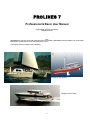
1
PROLINES 7
Professional & Basic User Manual
Copyright 2003 (c) Vacanti Yacht Design
All Rights Reserved
Note:
PROLINES Basic lacks most of the CAD output features that are available in PROLINES Professional. A Basic user will be limited
to2D DXF files, printed tables of offsets, and printed screen copies.
This complete manual is available on line under HELP.
Designs by Alex Simonis
Design by Don Dunbar
1
PROLINES 7 Contents
Technical Support
4
Technical Support
Technical Support Limitations
Free Software Updates
Just Starting Out
7
Introduction to PROLINES
PROLINES Basic
PROLINES Professional
Register PROLINES
System Requirements
9
PROLINES Main Screen
14
Using PROLINES Tool bar
Calculations
50
Stability Calculations
Hydrostatics Calculations
Wave & Friction Drag
Curves of Area and Wetted Length
Creating CAD Files
56
DXF Files
Skin Thickness Deduction
Tips for Viewing and Exporting Hulls
CADKEY Files
IGES NURB File
"Special Stations, Waterlines & Buttocks"
Exporting Other Files
65
IMS .OFF Files
GHS Damaged Stability Files
Stability Data Files
3D CAD Rendering Files
Design
18
Beginning A New Design
Measure Markers
Editing A Design
Visual Vertex Spreadsheet
Adding Control Vertex Rows or Columns
Deleting Control Vertex Rows or Columns
Changing Spline Tension
Fairing the Hull
Special Editing Tools – Offset Vertices
Multihull Design
Chined Hull Design
Creating A Deck
2
PROLINES 7 Contents Continued
Design Tools and Aids
PROLINES 7 Options Menu
Adding Keels and Rudders
69
Importing 3D DXF Keel And Rudder Files
Importing DXF Hull Files
47
Importing A DXF Files As A Reference Hull
Importing A DXF File As Vertex Control Points
Printing
72
Printing A View Of the Hull
Printing A Table of Offsets
3
Technical Support
Technical Support Limitations
Free Software Updates
4
TECHNICAL SUPPORT
Before you contact Vacanti Yacht Design for Technical Support you MUST first:
1) READ THE USER MANUAL
2) Verify that your computer is free of Viruses
3) CHECK our Home Page on the INTERNET for a Revised Version of PROLINES
The address is http://www.vacantisw.com
3) Verify that you know the exact steps that lead to the problem.
4 You MUST first REGISTER your copy by sending us:
A) Your name and address
B) A 24-Hour FAX Number - we will not make attempts to call at
specific hours of the day OR E-MAIL Address. E-MAIL is MUCH PREFERED.
5) All Users must provide at least ONE of the following:
A) 24 Hour FAX number. The fax must be available AT ALL TIMES. We
cannot call WORLDWIDE from the WEST COAST of the USA to accommodate
your schedule. We will try to reply to your fax ONCE. If it is not operational, we
will not retry. Include your FAX number on your FAX to us! Our Fax
Number: 425 413 2815
B) E-MAIL Address: This is the BEST possible solution. Using e- mail we can
respond at anytime, we can accept PROLINES design files that you create as
attachments to you letters. We can return these files to you with
recommendations and file corrections. Contact Vacanti Yacht Design LLC at
[email protected]
C) 24-HOUR TELEPHONE with Answering Machine - USE THIS OPTION
FOR ONLY THE MOST CRITICAL ISSUES, This must involve potential loss of
business. In this case - be aware that we may call this number at 3AM YOUR
Time. We will leave a message or if you are available, we will talk to you
directly. We cannot be held accountable for disturbing families at sleep if you
use this option.
5
REPORTING A BUG / ERROR
PLEASE - Verify that the error can be repeated. Clearly and in as much detail as possible
describe what steps were followed and how the error occurred. Include your 24-Hour Fax
number, your E-mail address or your 24 Hour Phone Number ON ALL
CORRESPONDANCE.
TECHNICAL SUPPORT LIMITATIONS:
Vacanti Software currently provides Free Technical Support. This free support is only
possible if we are allowed to reply to you at our convenience. Because we provide this
support worldwide, your call or fax or e-mail to us may arrive at any hour of the day or night.
Therefore it is impossible for us to reply to you on a schedule you supply.
If your FAX or phone is not operational 24 HOURS a day, do NOT expect a reply. We will
attempt a reply ONCE and if the fax is not operational, we will NOT retry. It is impossible for
us to attempt to contact customers worldwide on a schedule.
We cannot provide “online Teaching”
Unfortunately, our low prices do not allow us to provide the ability to call you and coach you
in the use of PROLINES. If you are a new computer owner, we suggest that you read our
manual and make an effort to carefully work through a design yourself. New computer users
should expect to spend several hours getting used to the conventions of Windows, Windows
95, Computer Aided Drawing (CAD) programs and other information.
We are constantly adding information to our user manual and updates of on-line help will be
made as often as possible. We are developing “How To Movies” that will actually show
PROLINES in action. Please check our INTERNET HOME PAGE for updates or check new
updates.
PROLINES has been in use around the world for over 13 years. It has been used to create
everything from canoes and kayaks to huge barges and fast passenger vessels up to 100
feet long. PROLINES has been described as the easiest yacht / boat design software to
learn.
FREE SOFTWARE UPDATES:
Free software updates are available on-line at our web site or you can request a copy of our
latest PROLINES release by mail, phone, fax or e-mail.
1) Download new software at: http://www.vacantisw.com
2) e-mail a request for updates to: [email protected]
3) Fax a request for updates to: 425 413 2815 (Dial International long distance for the
USA)
6
Just Starting Out
Introduction to PROLINES
PROLINES Basic
PROLINES Professional
Register PROLINES
7
Introduction to PROLINES
PROLINES was first created in 1985 as one of the first PC based hull design programs to use B-Spline
Surfaces (NURBS). The decision to use B-Spline was based on the fact that this new mathematical basis was
specifically created to permit the development of virtually any possible shape, including those containing both
curves and chines, chines alone and simple smooth hulls.
PROLINES 7 represents a major change in the numerical structure of PROLINES. This new version has a
completely new “NURB Engine” that is used to compute true Non-Uniform Rational B-Splines (NURBS). This
new engine is faster and more efficient and allows the adjustment of the spline tension under each vertex
control point. The ability to create local chine breaks permits designers the ability to create detailed deck
structures such as local chines along a coach roof and cambered deck or chines or tight radii within the cockpit
well of a sailboat. This powerful new function is available by right clicking on any vertex control marker.
Developable hull shapes, those that can be created from sheet materials such as aluminum, plywood or steel
are also possible with PROLINES. A separate program called B-PLATES is used to generate flat plate patterns
for sheet materials. Any plate that cannot be developed within B-PLATES may be corrected within B-PLATES
by using the Gaussian curvature display and many of the same mouse editing tools that PROLINES has. Please
refer to B-PLATES documentation for more information.
PROLINES was created specifically to be easy to use. Therefore one of its most important features is the ability
to use Parametric Hull Design. Parametric design simply means that the user creates an object by specifying
the object type (Chined Hull or Smooth), and the dimensions of that object such as its length overall and beam
at the deck. The designer is not required to build each shape "stick by stick" as is the case in many CAD
programs. In this release of PROLINES, we have enhanced the parametric hull design function by adding the
ability to specify a transom or stern type at design time. The designer has a choice of open, flat, rounded or
canoe stern shapes.
When creating a hull design, the hull must not only be fair, it must also meet the design objectives for
displacement, intact stability, prismatic coefficient, block coefficient and a host of other factors. Therefore,
PROLINES hydrostatics and stability computations are built in. These features can be accessed at any time
during the design process. It is possible to move a vertex point and click twice to see full hydrostatics displayed.
We encourage you to open one of the sample designs provided with PROLINES (File, OPEN.. Select a file
name) and then to explore the program by looking at each of menu lists. Take some time to look at each menu
and try to get an idea of the functions PROLINES provides. With this simple knowledge, attempt to modify the
hull shape by choosing items such as Move Vertex with Mouse in the Spline menu. Try Calculate Hydrostatics in
the CALC menu. During this exploration take note that PROLINES provides pop up help just as the mouse is
moved around the screen. Position the mouse over an icon or speed button and within 2 seconds a button name
will appear in yellow at the cursor. At the same time, in the lower left corner of the screen, a single line of text
explains how to use the button.
Have Fun Exploring!
8
PROLINES 7 System Requirements
PROLINES 7 is a full 32 bit program designed to operate under Win 95 / 7 or NT. It requires
at least 16 Megabytes of memory, 10 MB of free hard disk space, a mouse or other Windows
pointing device, a graphics card capable of at least 16 bits per pixel color. PROLINES must
be used on a display of at least 640 x 480 pixels but at least 1024 x 768 pixels will yield far
better performance. Best performance in rendering hull shapes in PROLINES will result with
graphics cards that provide a full 24 bits of color per pixel (millions of colors).
PROLINES 7 makes use of the OpenGL professional rendering software provided on all new
computers. Therefore more rapid graphics performance is made possible when using 3D
graphics accelerators that support OpenGL. Older computers will require substantial time to
render the hulls to high definition without a 3D accelerated graphics card.
9
PROLINES Basic
PROLINES Basic is built from exactly the same code that was used to create PROLINES
Professional. We have removed the code for those sections of PROLINES Basic that are not
included. PROLINES Basic does not include:
1) 3D DXF Files
2) CADKEY Files
3) IMS .OFF Files
4) IGES NURB Files
5) General Hydrostatics Systems (GHS) Damaged Stability Analysis Files
6) Other Especial Purpose Files
Basic does provide the ability to export 2D DXF Files, print Tables of Offsets, Stability and
Hydrostatics data.
As a cost savings measure to make PROLINES Basic available at its low cost, Vacanti Yacht
Design distributes the same user manual for both Professional and Basic Versions. We also
ship the same demo program for both PROLINES Basic and PROLINES Professional,
because the differences between the two programs lie in output capabilities. These CAD
output functions are turned off in the demo version and so no observable differences exist in
the demo in PRO Vs Basic.
10
PROLINES Professional
The professional version of PROLINES has a 13-year legacy of development. Its initial
development occurred in DOS, but beginning with version 6.0, PROLINES moved to
Windows as a 16-bit application and PROLINES 7 is a 32-bit application under Windows 95 /
7 and Windows NT. PROLINES is developed using a new state-of-the-art compiler known as
DELPHI 3 from BORLAND International.
PROLINES 7 for Windows NT and Windows 95 / 7 is 3 to 4 times faster in execution.
PROLINES 7 and PROLINES Basic are built from exactly the same computer code.
However, we have eliminated some of the code from PROLINES Basic, which limits its ability
to provide certain types of 3D CAD files, and prevents Basic from reading 3D DXF files as
well. Certain other features such may also be limited in PROLINES Basic. PROLINES 7
Professional will soon offer even more compelling features that will not be found in
PROLINES Basic. In particular, PROLINES 7 Professional will include multiple NURB
surfaces.
11
Register PROLINES
PRINTER MUST BE TURNED ON.
PROLINES is protected from pirating by Software Copy Protection. Each copy of PROLINES
will be ”locked” to the first computer it is run on. When PROLINES is installed and run for the
first time the message window shown below will be displayed. There are two buttons on the
bottom of this form – one labeled “Close Dialog and Contact Vacanti Yacht Design”, the other
button labeled “Unlock PROLINES” is used after you have received a computer Key Word
from Vacanti Yacht Design.
Press the “Close Dialog…” button the first time you run PROLINES. A special registration
Send this number
to Vacanti Yacht
Design
Vacanti Yacht Design
will send this number
back to you.
FAX to 425 413 2815
form will be printed that contains a computer number that is unique to your computer.
PROLINES will then close. Send this number along with your name and address to Vacanti
Yacht Design by e-mail or fax using the information printed on the form or on the dialog box.
Vacanti Yacht Design will send back to you a computer “Key Number”. Run PROLINES again
and enter this key number in the space provided for it on the Registration Dialog. Then press
Unlock PROLINES. SAVE the Key Number in a safe place.
The key number will be saved in a PROLINES .ini file that must not be disturbed. If the file is
erased or corrupted, the registration form will be displayed and you may re-enter the key
number.
UPGRADING COMPUTER HARDWARE
If the computer hardware that is used to run PROLINES is substantially changed it may fail to
run and present the registration form. Should this happen, please contact Vacanti Yacht
Design and describe the upgrades that have been made. If you purchase a new computer
12
Using PROLINES on More than One Computer
If you wish to use PROLINES on more than one computer at different times, you must
contact Vacanti Yacht Design. Special arrangements may be made for a second key number.
If you wish to operate PROLINES on two computers at the same time you must purchase a
second copy of PROLINES, at a discount.
13
PROLINES 7 Main Screen
Using PROLINES Tool Bar
14
Using PROLINES 7 Tool Bar
The tool bar shown above gives the designer access to the most often used functions within
PROLINES. The basic name of each function is available by simply resting the mouse cursor
over one of the buttons and after a few seconds a small yellow help balloon will appear with
the button name written inside. Additional information about each button is also available in a
short sentence written in the status line at the bottom of the screen.
More extensive descriptions of each button are presented below. Each button is described in
order from left or right. For example the first button is the open folder, used to open an
existing file.
Open A File
Clicking this button will bring up a standard Windows dialog box with all PROLINES hull
designs found in the current directory. This button cannot be used to read CAD files or other
file formats. It is only used to open an existing PROLINES design file (extension .phl).
Save This File
The floppy disk image on this button indicates that the current PROLINES design that is on
screen will be saved. Other files such as reference hull files or CAD files are not saved with
this button.
Print the Screen
The printer image on this button implies that the contents of the currently active view window
(window title bar is highlighted) will be printed at the resolution of the printer and in color if the
printer supports color printing.
Printer Setup
The set of tools image shown on this button means that you will find tools for changing the
current setup of the active windows printer. Pressing this button will show the Windows
standard Printer Setup dialog box. in this box you will be able to change printer resolution,
and paper orientation.
Calculate Hydrostatics
The hand held calculator symbol on this button indicates that clicking the button will cause
PROLINES to compute a complete set of Hydrostatics information, such as displacement,
centers of gravity and various hull shape coefficients.
Change Lines Drawing
The crossed lines on this button image correspond to the stations, waterline and buttocks
traditionally found in hull drawings. Selecting this button allows the designer to turn various
lines on or off and toggle between showing NURB splines and traditional stations etc.
Vertex Net ON or Off
15
Clicking on this button causes the program to either display or hide the vertex control points
that define the hull shape. The vertex markers must be turned on to use any of the mouse
editing tools
UNDO
The circular arrow symbol will become active after you have down anything that alters the
design from its initial state. You may sequentially UNDO up to 90 steps. One word of caution
however, do not attempt to Undo a Make a Chine Break change. This change must be
removed first with Remove Chine Break from the SPLINE Menu.
Render Hull
This button is seen as a rendered image. Click this button to open the OpenGL rendering
dialog.
Zoom In
The magnifying glass with a plus (+) sign indicates that you can enlarge a desired section of
a view. Click on the button and the cursor will become an UP Arrow symbol. Move the cursor
to the upper left of the area you wish to enlarge. Click and hold the left mouse button down.
As you drag the mouse a zoom window box will be drawn. Release the mouse button when
the area you wish to enlarge is enclosed within the zoom window box.
Zoom Out
The magnifying glass with a (-) sign indicates that the active view will be returned to normal
view. Therefore, to cause a zoomed view to be returned to its normal size, first select the
desired view by clicking the left mouse button in the title bar. When the desired view title bar
is highlighted, click on the Zoom Out button.
If for any reason the views are not drawn properly, select View – Fit All Views to Windows.
View Buttons
The view buttons cause the view given by the title of the button to be drawn. For example, the
button labeled BODY will cause the Body View to be drawn.
Animate
The Animate button allows the designer to see a “movie” of the hull played for him in the
perspective window. PROLINES will display
a dialog that asks how long to delay before
drawing the next view. The animation
sequence will show several views from
above and below the hull. The animation
control dialog will remain open so that you
may stop, restart or change the speed of the
animation.
Spline Tension
These are display only windows that cannot be edited. They indicate the spline tension levels
along the length and vertically on the hull.
16
X and Y Coordinates
These are display windows that cannot be edited. They indicate the current position of the
mouse in inches or millimeters depending on which units are being used in the drawing.
Calculator
Click the down arrow located on the right edge of the calculator to open the calculator key
pad. Use this handy utility for unit conversions or other quick computations. The values
produced by the calculator are not used by PROLINES.
About
The button provides special information about PROLINES.
Information – Help
PROLINES provides extensive on-line Help. Clicking this button will provide information on
how to use PROLINES. A great deal of the information that is found in this manual is
available on-line.
17
Design
Beginning a New Design
Measure Markers for Existing Designs
Editing a Design
Adding Control Vertex Rows or Columns
Deleting Control Vertex Rows or Columns
Changing Spline Tension
Creating a Chined Hull Design
Fairing the Hull
Multihull Design
Adding A Deck
18
Begin A New Design
PROLINES allows a designer to create a new design with:
Parametric Hull Design
Existing Table of Offsets
Import 3D DXF File
Parametric Hull Design creates a new hull by asking for just the basic hull parameters such as length overall,
freeboard, draft, beam at the deck, chined or round hull, open, flat or round transom or stern. PROLINES uses
the dimensions to create a hull shape that is already fair or very nearly fair. The designer should then modify the
hull to suit his specific design task by moving vertex points and adding, subtracting or moving rows and columns
of vertex points.
To create a new design using parametric data, select FILE, NEW..., Parametric Hull Design. Now select the hull
type that is the closest to the hull type you wish to design. Be sure to specify the measurement units that will be
used to specify your design. If units of meters are chosen, PROLINES will convert that data into millimeters after
it creates the design on screen. If Units of FEET are chosen, the data will be converted to INCHES after the hull
has been created. Next be sure to specify the type of stern or transom. Change the dimensions of the hull
according to the planned design. Carefully check to see that all of the choices and dimensions have been
properly selected and click OK. The hull will be drawn in Body view. Modify the default hull shape to meet your
design needs. Use the editing tools found in the EDIT, SPLINE and TOOLS menus.
Existing Table Of Offsets usually are taken from a detailed paper drawing or from a hand sketch. PROLINES
only requires data taken from station oriented sections through the hull. PROLINES does not require nor can it
use offsets from waterlines, buttocks or diagonals. Offset data entered into PROLINES Visual Vertex
Spreadsheet are considered to be columns of vertex control point locations. The data should at least be nearly
vertical data just as a station is vertical. The number of offsets entered for each column must be the same for
each column.
Import 3D DXF Files to create a hull shape within PROLINES based on data that has been digitized or created
in a 3D CAD program such as AutoCAD, CADKEY, DesignCAD 3D or others. PROLINES is expecting elements
in the DXF file that are either LINES or POLYLINES, not Splines or ARCS or other elements. The data must be
19
3D and contain Beam, Height and Length. The axes in PROLINES are defined as follows: X=BEAM, Y=Length
Along The Hull, and Z=Height above or below DWL or LWL or other reference line.
The data in a 3D DXF file may be read as offsets for vertex control points to create a hull directly from the DXF
file IF the file meets the following criteria:
1)The data is station oriented with bow and stern - no waterlines or other data.
2)The number of line elements or the number of vertex points per polyline is the same on each station and there
are less than 30 points per station or vertex column.
3)The number of "stations" is 30 or less.
If the file does not meet these criteria, then it can be read in as a simple drawing and displayed for reference on
the screen. This makes it possible to modify a hull created by PROLINES Parametric Hull Design so that it
overlays the reference hull by using PROLINES editing tools.
Import GHS Files GHS stands for a well known General Hydrostatics program distributed by Creative Systems
of Port Townsend Washington, USA. GHS is a very capable damaged stability analysis program that is
frequently used to capture data for ships and barges before modifications. The data used by GHS is very similar
to PROLINES in that it is all station oriented data, with no waterlines or other planar cuts. The only difficulty with
GHS files from PROLINES perspective is that each set of station data in GHS has a different number of points
or offsets. A b-spline or NURB surface like the one used by PROLINES requires an equal number of vertex
points at every station. To correct for this problem, PROLINES reads GHS files and automatically either
interpolates to add additional data points when too few are present or deletes some data points when there are
too many.
20
Measure Markers
With the virtually unlimited possibilities of hull types and shapes it is impossible to provide a
means to automatically adapt PROLINES off-surface vertex control points to an existing hull
shape. Therefore we have provided a means to enter offset data for an existing hull and
display that data as special markers (an X) on screen in all views. It will be the designers task
to make small adjustments to the vertex control points such that the stations pass through the
measure marker locations at the center of the X.
Basic Concept
The concept for using Measure Markers to rapidly enter an existing hull is as follows:
1)Enter a Table of Offsets in the Visual Vertex Editor
2) Save the File as a PROLINES Hull
3)Convert the PROLINES Hull file into Measure Markers
4) View the PROLINES hull and the Ma sure Markers together
5) Move the hull vertex points so that the hull passes through the Markers
Step By Step
The Measure Markers are created and used as follows:
1) Select File, NEW, Enter Hull Offsets From The Keyboard
2) Enter the basic hull dimensions and number of desired stations and number of
points per station.
NOTE: You must enter the same number of points per station. Do not enter
zeros (0) where data is not available from a Table of Offsets. Instead - estimate the locations
of additional points between the offsets that do exist to fill in the table.
3) The Visual Vertex Editor will appear with a preliminary set of stations and vertex
locations that will form a crude "Vee" shaped hull. Edit these locations with the Table of
Offsets from your existing hull.
4) Carefully check the hull offsets in the Visual Vertex Editor and save the hull file with
the FILE SAVE or Click the Save File button on the tool bar.
5) Select FILE, NEW…, Convert a Hull File to Measure Markers. Locate the
PROLINES hull file that was just
saved and open it as a Measure
Marker File.
6) The Measure Markers and
Hull vertex locations will be drawn
and will exactly lie on top of each
other.
7) Select EDIT STATION
WLS BUTTS Settings, and set the
station spacing to match the
spacing of the stations entered in
the Visual Vertex Editor. If the
stations are placed at uneven spacing then select EDIT - Special Stations WLS, Butts. Use
this function to draw stations at the same locations as the vertex columns and measure
markers. This step is critical because it makes it possible to verify that the hull is passing
through the measure marker locations.
21
8) Begin editing the hull vertex points so that the stations pass through the measure
markers. This should require pulling the vertex points out slightly in beam.
Special NOTES:
It is not desirable to enter a very detailed and extensive table of offsets for an entire
hull, this will create confusion in trying to view many vertex and measure markers on screen
at the same time. Instead it would be wise to use the fewest stations and the least number of
points per station that adequately describe the hull.
The basic concept for Measure Markers is to enter data once and allow that data to be used
once as the measure marker locations and then reused as the initial locations of the vertex
control points. This is all automated by the Convert Measure Markers function. However, if all
of the measure markers are displayed for the entire hull, it may be very difficult to determine
which markers are on which station. Therefore, the following strategy should be employed:
1) Enter the vertex control point locations as described above.
2) Create two or three copies of the new hull and save them as PROLINES hull files.
This is easy to do by using the FILE, SAVE AS function.
3) Using one of the copies, delete all but the first 1/3 of the vertex columns. Save this
new smaller file. Open a second copy and delete the first 1/3 and last 1/3 leaving the middle
1/3 of the vertex columns. Save this new smaller file. Open a Third copy and delete all but the
last 1/3 of the vertex columns. Save this new smaller file.
Now convert these smaller files (1/3 of the vertex columns) into separate Measure Marker
files for the forward middle and aft sections of the hull. Now displaying the Measure markers
will be simplified and the location of markers is clear. You may create as many separate
Measure Marker files as needed to simplify the task, and you should only have to enter the
data once.
22
Editing the Design
Editing Tool Buttons
PROLINES offers several means to alter the shape of a hull. They include editing with the mouse or changing
vertex control points numerically with a spreadsheet or keyboard. If you are working towards a design that has
very specific dimensions required at a specific location on the hull, it may be most efficient to adjust thee design
numerically. There are two options:
1) Edit a Single Vertex Numerically
2) Edit A Column Numerically.
Edit a Single Vertex Numerically.
This option permits you to right click on a single vertex in any planar view (Body, Plan, and Profile) and bring up
a dialog box that contains the 3D dimensions of that vertex point. Optionally, select EDIT, EDIT SINGLE
VERTEX. The current dimensions of that point
are shown at left and may be changed in the edit
box on the right. When all of the dimensions
have been set to the desired value click OK to
accept the new values. All of the views will be
updated to show the new hull shape.
The Visual Vertex Editor (VVE - See the EDIT
Menu) is another way to edit vertex points
numerically.
Edit A Column or Row Numerically
This option is used to view one column of vertex
control points that may define a station location
on the hull. to use this option, select EDIT,
VISUAL VERTEX EDITOR. The Visual Vertex
Editor (VVE) will appear in a window. When the
window first opens, the spreadsheet on the left lists the 3 dimensions of each control vertex point on column 0
(zero), which most frequently will be the bow. To the right of the spreadsheet is a Body view of column 0 (zero).
Below the column drawing are three buttons labeled Body, Plan, Profile. Click one of these to change the view
of the current column.
Just below the spreadsheet is a panel that contains a spin editor labeled "Column". Click on the up arrow of the
spin editor once and the data in the spreadsheet will change to show vertex column 1. The drawing on the right
will also show vertex column 1.
The offsets of the entire column of control vertex points may be changed numerically by editing the values in the
spreadsheet. Changing the data will be reflected as changes in the shape of the column in the drawing to the
right. If the value you entered is in error, it should be obvious by checking all three views (Body, Plan, and
Profile). If the shape of the vertex column is not what you expected, then the data entered in the spreadsheet is
incorrect. Correct the data in the spreadsheet or click on the UNDO button.(Undo may not be available in early
releases of PROLINES)
Editing With A Mouse.
The mouse can be used in at least 3 ways. First, it can move a single vertex point at a time in any planar view
(Body, Plan, and Profile). Second, it can cause an entire row (along the hull length) or an entire column (along
hull height) to be Translated or shifted from its current position. Third, it can be used to move an entire row or
column Proportionally.
23
Move A vertex Point with the mouse
Vertex Control Marker
PROLINES 7 allows “Instant Editing” of the hull. You will
notice that the mouse cursor is a + sign as it is moved over
the Body, Plan or Profile windows. Position the + symbol in
the middle of a red square vertex marker. Now Click the left
button and hold it down as you move the mouse. Lines
connecting the vertex to its neighbors will follow the mouse.
The Options menu allows you to select the hull to be
updated as you move the vertex or to move just the vertex
lines and update the hull after the move is complete.
When the vertex is in a new position release the left mouse
button to drop it in place. The cursor shape will remain a +
sign, allowing the repeated movement of other vertices.
Vertex Tension
Control
Changing Local Vertex Spline Tension
PROLINES 7 has a completely new BSpline computational engine. This new
capability allows the designer huge new
flexibility in hull design. For example,
previous versions of PROLINES required
the designer to align multiple vertices to
create a local chine. Now to create a
local chine or sharp break PROLINES 7
allows the tension of each vertex point to
be adjusted. Simply right click on the
vertex control you wish to adjust.
PROLINES 7 will show the new
numerical offset editing dialog. Change
the default vertex weight from 1 to 5 to
create a very sharp break at the vertex location. Conversely, set the value to 0.1 to virtually
remove any influence of the vertex on the hull shape.
24
TOOL Menu
The TOOL menu contains several powerful functions that are very useful to the designer. The
tool functions are shown in this image.
The first TOOLS function group includes the ability to
Stretch or Shrink the hull to any overall dimension, Shift
the hull up, down or right or left or Trim and heel the
hull.
STRETCH / SHRINK HULL
This function allows the designer to change any one
overall dimension, such as length or all overall
dimensions (Beam, Length and Draft) all at the same
time. These changes may be in the form of a
percentage or in the form of an exact new dimension.
Changing the hull overall changes all dimensions
proportionately.
Click on the radio button that corresponds to the chages
you would like to make in the hull. For example, if the
beam is to be changed from 80 inches to 85 inches(this
is the half beam measured from center line to max beam
at the deck) then Click the button beside “Half Beam”.
Now click on “Set Dimension” and enter 85 in the edit
field labeled “Dimension”.
To increase the overall beam of the hull 10% then select
“Half Beam” and “Scale By Percent”. Enter 10 in the edit
field labeled “Percent”. Using the previous example, the
overall beam of the hull would be scaled from 80 inches
to 88 inches for an increase of 10%. Similarly, the beam
could be scaled down to 72 inches if the user had selected “Half Beam”, “Scale by Percent”
and entered –10% in the “scale” field. (80-0.1*8=72)
SHIFT HULL
This function is used to translate the hull with
respect to the coordinate system that
PROLINES maintains. For example, the dialog
shown here indicates that the user wishes to
shift it along its length relative to the bow. If
the user enters 34.6 the hull will move aft 34.6
inches (or millimeters). Therefore if the bow
previously touched the vertical “0” reference in
the profile or plan views, it will now rest 34.6
inches aft. If the user enters –34.6 the hull be
moved 34.6 inches forward and will now likely project in front of the bow reference. Similarly,
the user can choose to move the hull up or down to decrease or increase draft. Select “Shift
Bow to Zero” to automatically adjust the forward most point on the hull such that it
25
corresponds to “0”. With this adjustment made, the user can readily select station spacing
relative to the bow at even increments.
Visual Vertex Editor
Selecting EDIT, Visual Vertex Editor, accesses the Visual Vertex Editor.
The visual vertex
editor was
created to allow
a designer to
numerically or
visually (using a
mouse) edit the
vertex control
points of each
vertex row or
column. The left
side of the editor
is a spreadsheet
that displays the
beam, distance
aft and position
above or below
the LWL of each
vertex point. The
right side of the
display is a
drawing of the
vertex column that first appears in body view. The designer may choose to view each vertex
row or column in Body, Plan or Profile by clicking the view buttons below the column drawing.
Selecting the row or column check box under the view buttons makes a choice of row or
column display.
The drawing includes the numbers of each vertex control point as it is indexed by
PROLINES. These same index numbers correspond to the vertex numbers displayed at the
left edge of the spreadsheet. When a vertex point is edited numerically in the spreadsheet,
the drawing will be updated to show the new vertex position. If the vertex point is moved in
the drawing at right, the new vertex location will be displayed in real time within the
spreadsheet.
The Visual Vertex editor is the most powerful way to create complex shapes such as a cut
through a deck where the deckhouse or cockpit is placed. The numerical data can be used to
insure that flat cockpit soles are indeed flat and exactly the same height and width at each
station location. To see just how the editor can make a hull shape more readily understood,
open one of the ample hull files called House, “Cruzr” or “Cr_racr”. These complex shapes
can be easily understood and refined in great detail using the Visual Vertex Editor.
26
Selecting a Vertex Column or Row
At the left side of the editor and just below the spreadsheet data is a spin control labeled
Vertex Column (Row) Number. To change to a column located farther away from the bow
click the UP arrow on the spin control. To move to columns located close to the bow (Bow is
Zero “0”) click the DOWN arrow. The drawing at the right of the editor will show a new column
each time the UP or Down Arrows are clicked, and the spreadsheet will show the vertex
offset data.
Moving a Vertex with the Mouse
To move a vertex to a new location with the mouse, locate the mouse cursor in the center of
a vertex marker box. Click and hold the left mouse button while you drag the vertex to a new
location. Watch the numerical values in the spreadsheet to see the new location values. The
spreadsheet data will update as the mouse moves. To stop moving the vertex point simply
release the left mouse button.
Editing A Vertex Numerically
Any vertex point can be changed numerically by placing
the mouse pointer over the value to be changed and
clicking the left mouse button once. An editing window
will appear with the desired value in it. Change the
number to a new value and click OK.
It is also possible to force all of the values of a column to
have a constant value by entering just one value. The
most common example is to force all vertices to lie at
the same distance aft the bow on vertical line. To do
this, look at the lower left corner of the editor. There you
will find three data lines describing beam, distance aft
and position relative to the LWL. To force all values of
distance aft
the bow to a
common
value,
position the
mouse
cursor over the distance aft radio button at the
left and click the left mouse button. Now change
the value of "Aft Bow" to the desired value and
then click the CHANGE button to the right of the
data lines.
Choosing A View
Three view buttons labeled BODY PLAN and
PROFILE are located just below the drawing of the vertex column. Clicking one of the buttons
will display the vertex column as it is seen in the selected view. The editor displays each
27
column in BODY view by default. Once the view has been changed, the display will remain in
that view until another view is selected.
UNDO
The Undo function is located near the center of the editor. The editor keeps a backup copy of
the hull available at all times. The backup does not include any changes made to the vertices
unless the SAVE button is selected at the center of the editor. Selecting UNDO will remove
all changes to the current column up to the last time SAVE was selected. UNDO does not
affect the hull file saved on disk.
Saving All Vertex Locations
Changes made using the editor made using the editor may be saved incrementally to
MEMORY( not the hard disk file) by clicking the SAVE button near the center of the editor. If
at any time an error is made then selecting UNDO will remove all changes to the current
column up to the last time SAVE was selected. To Save the hull permanently in a File you
must select FILE SAVE or click the Save File button on the tool bar.
Leaving The Visual Vertex Editor
You may exit the visual vertex editor by either selecting OK or Cancel. If you choose OK, all
of the changes that have been made will be saved in MEMORY and the hull shape redrawn
with the new vertex locations included. To make a permanent copy of the changes you MUST
select FILE - SAVE, or click on the Save File Button on the tool bar.
If you choose Cancel, then all changes made to the hull will be erased and the original hull
redrawn. It is important to note however, that if at anytime the changes in the editor were
saved to memory with the SAVE button, then only changes made after the save will be
erased.
28
PROLINES Vertex and Row Numbering System
PROLINES identifies each vertex row or column by a number. The image above shows a
single vertex column numbered by PROLINES. It can be seen that this is column 4, and that
rows are numbered from 0 to 11 in this image. Rows are counted from 0 at the fairbody or
cener line and columns are counted from 0 starting from the bow. You can show the
numbering system by selecting Options, Label Vertex Rows and Columns. It is easy to show
just a single row or column by selecting Options, Draw Single Vertex Net Line.
Adding Control Vertex Rows and Columns
Rows and columns of vertex control points may be added to allow additional control over the
shape of the hull. The addition of rows of vertex control points is frequently done to define
simple chines, or more complex lifting strakes. The addition of columns is frequently done to
gain additional control over the hull at a desired location aft the bow, or to match up with
existing stations and tables of offsets.
There are two means to add new rows or columns. They are:
1) Positioning With Mouse
2) Insert by Row or Column Number
Positioning With Mouse
29
PROLINES allows the user to indicate where he wishes to place a new row or column of
vertex control points by simply clicking the pointer on any planar view, such as Body, Plan or
Profile. The row or column will be placed in the middle of the vertices that are immediately
above and below the mouse position. This is done to insure that the least possible change in
hull shape will occur after the new vertices are added.
To Add a Row or Column of Vertex Control Points:
1) Vertex control points must be drawn - Select the Vertex Net ON/Off Button on the tool
bar if vertices are not shown.
2) Select EDIT, ADD VERTEX ROW... or ADD VERTEX COLUMN... Then With Mouse
3) Cursor becomes an UP Arrow symbol
4) Click the mouse between two existing rows or columns.
5) The new vertex row or column will be added and the hull will be redrawn.
Insert By Row or Column Number
Rows and columns can be added by specifying the number of the vertex row or column that
the new row or column will follow. For example, if the user selects row 5, the new row of
vertices will be inserted between rows 5 and 6. Refer to the image above to view PROLINES
numbering system.
To Add a Row or Column of Vertex Control Points:
1) Vertex control points must be drawn - Select the Vertex Net ON/Off Button on the tool
bar if vertices are not shown.
2) Select EDIT, ADD VERTEX ROW... or ADD VERTEX COLUMN... Then By Row /
Column Index
3) Enter the number of the row or column that the new row or column will follow.
The new vertex row or column will be added and the hull will be redrawn with the new
vertices included.
30
Deleting Control Vertex Rows or Columns
Rows and columns of vertex control points may be deleted if they have been placed in error
or simply are not required.
There are two means to delete rows or columns. They are:
1) Select With Mouse
2) Delete by Row or Column Number
Select With Mouse
PROLINES allows the user to indicate which row or column of vertex control points to remove
by simply clicking the pointer on any planar view, such as Body, Plan or Profile.
To Delete a Row or Column of Vertex Control Points:
1) Vertex control points must be drawn - Select the Vertex Net ON/Off Button on the
tool bar if vertices are not shown.
2) Select EDIT, DELETE VERTEX ROW... or ADD VERTEX COLUMN... Then With
Mouse
3) Locate the + Cursor over one of the square vertex control point markers (Default red
box)
4) Click the left mouse button.
The new vertex row or column will be removed and the hull will be redrawn.
Delete By Row or Column Number
Rows and columns can be removed by specifying the number of the row or column to be
deleted.
To Delete a Row or Column of Vertex Control Points:
1) Vertex control points must be drawn - Select the Vertex Net ON/Off Button on the tool
bar if vertices are not shown.
2) Select EDIT, DELETE VERTEX ROW... or DELETE VERTEX COLUMN... Then By
Row / Column Index
3) Enter the number of the row or column to be removed.
The vertex row or column will be removed and the hull will be redrawn.
31
Changing Spline Tension
Hull designs created within PROLINES are based on a special surface that is known as a
NURB (Non-Uniform Rational B-Spline) or B-spline surface. This special surface type was
created by mathematicians to allow the design of virtually any shape. One of the features of
B-Spline surfaces is the ability to change the
tension or stiffness of the curves.
PROLINES allows the designer to change the
stiffness of the splines in the lengthwise and station
oriented directions independently. Tension in the
spline is the same as using stiff or very pliable
battens. By setting tension to its lowest level of 1,
the splines act as if they are made of limp string,
and will lay in straight lines between the vertex
control points, and forming chine breaks at each
vertex point. This makes it possible to create a
chined hull by simply selecting a tension of 1 in the
station-oriented direction.
Medium
Tension =3
High
Tension =4
LOW
Tension =1
The pictures shown here are
samples of hulls, each with a
different station tension. The
picture labeled High is an
example of a stiff batten or a
spline with High tension set
at the maximum of 4. The
number 4 refers to the
mathematical order of the
spline. The picture labeled
Medium has a medium
tension of 3.
The picture labeled Low has
the very lowest tension setting, and it shows a chine at its center
point. The chine location would correspond to the location of a control vertex point. With the
lowest tension of 1 set, all splines appear as straight lines. Setting the station tension to 1 is
one way to design a chined hull. A chine will appear along each row of vertex control points.
Selecting a double chined powerboat hull when using the Parametric Hull design feature of
PROLINES, will create a hull of this type.
MAXIMUM POSSIBLE SPLINE TENSION
The highest tension available in either direction is not automatically a level 4. The number of
vertex control points along the spline limits the maximum tension. For example, a Tension of
1 requires 3 vertices, Tension 2 requires 4, Tension 3 requires 5 and Tension 4 requires a
minimum of 6 vertex control points. PROLINES will automatically limit the highest tension you
are allowed to select according to this rule.
32
INDEPENDENT SPLINE TENSION ADJUSTMENT
PROLINES permits the designer to adjust the spline tension along the length of the hull
independently from the tension vertically or along stations on the hull.
To change the tension of the splines:
1: Select SPLINE, The Spline Tension Dialog Box appears (Shown Above)
2: The Spline Tension Dialog Displays the Current Spline Tension Settings (Station Tension
=1 in the example above)
3: Click on the up or down arrows to adjust the tension of either or both spline directions
4: Click OK and the hull will be redrawn with the new spline tensions.
Fairing the Hull
To access the fairing features select the EDIT – Fair Vertex Column / Row / Fairbody &
Sheer or Chines.
Hulls created in PROLINES are based on columns of vertex control points. The columns may
or may not correspond to regularly spaced traditional stations. PROLINES allows the
designer to fair the hull at the location of each column of vertex points in any planar view
such as body, PLAN, PROFILE. If the vertex columns have been designed to match a set of
regular stations, then you are indeed fairing the stations in each of the planar views.
The first vertex column in any PROLINES design is the bow, which is assigned vertex column
number 0. Because the bow has little or no beam, it is best viewed in PROFILE when it is
faired. Attempting to fair the bow (column 0) in PLAN or BODY view is usually of little value.
Vertex column 1 and virtually all of the following vertex columns will offer the best viewing
and fairing in BODY view. PLAN and PROFILE views will be of little value in these cases.
Finally, the last vertex column on an open transom sailboat will be best viewed in PLAN, so
that the curvature of the stern can be smoothed.
33
Fairing Vertex Columns
To begin fairing, select EDIT, FAIR Vertex Columns. A special dialog box will appear that
contains four critical parts. The first part is the actual dimensioned plot of the station shape
shown here.
The location of each
vertex control point is
Station Curve
marked with a square
as shown at left. The
Vertex Control Points
Green bar shows the
shape of the actual
beam location of the
selected vertex.
station that is created
Selected Vertex
by this set of vertex
control points is
Select A vertex To
shown in the smooth
Move
red line just to the left
of the vertex column.
Click Arrows to move
The dimensions along
Vertex
the vertical axis
correspond to height
in BODY and
PROFILE views, and
beam in PLAN view.
The Horizontal axis
corresponds to beam in BODY view and distance fore and aft in PROFILE and PLAN views.
This is a fair furve,
except for a very
slight unfair area
near 10 inches of
beam.
To select a view the designer clicks the left mouse button on one of the view buttons shown
here. The current view is printed to the right of the view buttons.
The designer selects which vertex column to fair and which vertex on each column to move in
special areas shown at right. First the designer clicks the Vertex Column spin editor arrows
either up or down until the desired vertex column is displayed. Next the designers selects
which vertex to move by clicking on the Vertex Number spin editor up and down arrows until
the number within the editor matches the vertex to be moved. The fairing editor will show
which vertex is being selected by highlighting that vertex with a large green block. The image
above shows the “0” vertex highlighted in the station drawing on the right.
Next, the designer sets the amount the vertex will be moved with each click of the mouse or
each step by entering a value in the STEP SIZE edit box. Finally, to move the vertex up or
down by the amount specified in the Step Size edit box, the designer clicks on the UP or
DOWN arrows in the VERTEX POSITION area.
The final area that is displayed in the dialog is the plot of Curvature. A large amount of
curvature means that the vertex column has a sharp bend, and a small amount of curvature
means that the vertex column shape is nearly flat. The station curvature may change from
small curvature to large curvature and then small curvature again, but it must not reverse it
self twice. Examples of fair and unfair curvature are shown in the figure above. The fair
curvature line first increases in curvature then decreases. This is fair. The Unfair curvature
increases and decreases and then increases again.
34
REMOVING UNFAIRNESS
To remove the very slight unfairness shown at about 10 inches of beam in the example
above, the designer would note the beam location of the unfairness, then refer to the plot of
the vertex column and the station shape. He would note that in this case vertex number 1 is
closest to the unfair area. He would click on the Vertex Number spin editor until it reads
number 1. Next the designer should slowly move the vertex up or down or right or left by
clicking on the appropriate arrows in the Vertex Position area of the dialog. He will note when
the unfair region begins to smooth out and then stop editing.
It is not necessary to get perfect fairness in every station the first time it is faired. There is
some interaction between adjacent stations, where changes in fairing to station 1 can have
some affect on the fairness of stations 0 and 2, and in turn stations 0 and 2 will affect station
1. Therefore it is wise to fair each station from bow to stern once to remove only the most
serious unfairness. Once this has been done, the fairing can be repeated with much finer
adjustments. The smaller corrections will result in less influence on the adjacent stations. The
following pictures show examples of fair and unfair curvature curves.
Wrong! Must not Change
Slope more than 1 time!
YES!
Example of a Fair Curvature Curve
Example of an UNFAIR Curvature
FAIRING VERTEX ROWS
PROLINES 7 includes the capability to fair any row on the hull in either plan or profile views.
It is important to understand that the hull line generated in this fairing procedure is not a
waterline but rather a line that
First
Third
most closely corresponds to the
Change
Change
Unfair curvature.
shape of the vertex row that is
Second
shows > one change
being faired.
Change
in curvature slope
The Fair Rows Dialog that is
seen here shows vertex row
number one in Plan view. It is
very easy to see the unfair
nature of the vertex line in the
lower plot. However as the
offending vertex near 300
inches aft the bow is moved,
the fairing task requires the
detailed curvature plot shown in
35
the upper plot. A fair curve changes slope in curvature just once. Therefore a fair curve
would show a curvature that steadily increases and then steadily decreases. It must not
increase in curvature again.
FAIR FAIRBODY AND SHEER
PROLINES 7 has the ability to fair the hull fairbody (centerline) and Sheer (deck edge) in
Profile and PLAN views. The dialog is virtually identical to the Row fairing dialog shown
above, except that only the first and last rows of the hull can be faired.
FAIRING CHINED HULLS
First each chine break represents a mathematically infinite curvature which in turn creates a
spike in the curvature curve plot. Multiple vertices that are collected together also cause a
curvature spike. Therefore fairing chin ed hulls can either be difficult or impossible.
For example, it is not possible to fair a station when the spline tension in the station direction
has been set to 1. This means that the hull is made up of straight lines and chine breaks
everywhere. In this case there is no definition of curvature and the fairing function cannot be
used. It is also virtually impossible to to fair a hull with many chine breaks such as power boat
hulls with spray strakes.
Round hulls with a few chines can be faired over the regions that are smooth and round, and
not where the chines occur.
An example of a screen that allow the designer to fair the edges of the hull such as the bow,
stern, fairbody and sheer or deck edge is shown below.
36
Special Editing Tools - Offset Vertices
Frequently it is necessary to force one row or column of vertices to lay at a specific location
relative to another row or column of vertices. For example, when a designer wishes to create
spray strakes that have constant dimensions over the aft part of the hull. It would be valuable
to be able to choose one row of vertices as the master row, that has been faired in its final
location, and then an offset row that must lie a few inches to the right and below of the master
row.
OFFSET VERTICES was created with just this concept in mind. As a design example,
consider the desire to place a spray strake that is 2 inches high and 3 inches wide along the
aft part of the hull. The strake will be constant from vertex column 3 aft.
The designer would first select TOOLS, Offset Vertices. PROLINES will display a dialog that
requests the designer to select the starting and ending points of the vertex row or column that
will be offset relative to a master curve. To select a start or end point place the mouse cursor
over a vertex marker and click the left mouse button once.
The image above shows that the vertex row start and end points are marked by PROLINES
as 1 and 2. The designer has already selected the master curve as the row just above the
offset row. Placing the mouse cursor over any vertex on the master curve and clicking the left
mouse button once did this.
-3
PROLINES will now prompt the designer with the
vertex offset dialog box as shown above. In this
case the designer has requested that the offset row
be placed three inches inside (a negative was used)
the beam locations of the master vertex row. The
vertices of the offset row will be placed at the same
positions aft the bow and at the same height as the
master row, because zero offsets have been
entered.
The figure above shows that the vertices of the offset vertex row have been moved to the
same height and position aft the bow and placed 3 inches within the beam location of the
master curve.
If the same set of vertices had been set to 0 offset in all cases, the offset vertices would be
placed on top of the master curve. The location of two vertices at the same location will cause
a local chine break to occur between the start and end vertex locations.
37
Using + or - sign with the offset measurements:
1) A negative Beam Offset value means the vertices will be placed to the inside of the
master vertex beam location. A positive value will place the offset vertex outside the master
vertex location.
2) A negative Aft Bow offset will place the offset vertex in front of the master vertex or
closer to the bow. A positive Aft Bow offset will place the offset vertex aft the master vertex or
closer to the stern.
3) A negative Height Offset will place the offset vertex below the master vertex and a
positive height will place the offset vertex above the master vertex.
38
Multihull Design
PROLINES is not currently optimized for the design of asymmetric hulls. Therefore, it is
necessary to design a multihull boat or ship in one of the following ways:
1) Create each hull as a separate entity and collect the two outboard hulls of a
catamaran or the center hull and outboard hull of a trimaran in a commercial CAD
program.
2) Create a multihull by dividing it down its centerline and designing the center section
and outboard hull as a PROLINES hull. This concept is demonstrated clearly by the
screen shot shown here.
We strongly suggest that you make use of the Visual Vertex Editor to create a multihull
design if you decide to design from the centerline out. The editor makes it possible to clarify
what would otherwise be a confusing set of control point locations.
39
Chined Hull Design
Chined Hulls can be created by at least three means.
The first and simplest method is by setting the spline tension in the station direction to its lowest level of 1. By
doing so, one chine will lie directly below each row of vertex control points. The hull shape between each chine
is flat and without curvature. To set the surface spline tension along the station direction, select SPLINE,
SPLINE TENSION.., STATION TENSION, set tension to 1. Click OK and all views will be updated. Each chine
will be drawn along the length of the hull in the color defined for chines (default is red).
The second method allows a combination of curved hull shape and chines mixed. This method is only available
if the hull has a station tension of 2 or more. The current tension is displayed in the upper right of the main
screen. To create chines in round hulls, place rows of control vertex points (see Adding Vertex Rows/Columns)
at the positions where chines will occur. Now select SPLINE, Make A Chine Break.... Choose Make a Horizontal
Chine. The cursor will change into a + sign. Position the cursor on one of the square control vertex markers.
Click the left mouse button once and a chine break will occur along the selected vertex row (along the length of
the hull). The chine is shown as a red line or your chosen chine color. Repeat the process to add additional
chines.
CAUTION - In order to create chine breaks in a round hull, PROLINES must use duplicate vertex control points
at each location on the row. The number of duplicate vertices that it must use is determined by the tension in the
station direction for horizontal chines and in the longitudinal direction for vertical chines. For a station tension of
2, two sets of vertices are required and at tension of 4, four sets of vertices are required. Therefore, chine
breaks in round hulls can rapidly use up the 31 vertex control points allowed in each direction, especially if the
tension is high. IT IS ADVISED THAT THE LOWEST POSSIBLE TENSION BE USED WHEN CREATING
CHINES IN ROUND HULLS.
The third method allows partial or local chines to exist anywhere on the hull. A b-spline surface will produce a
chine or a very tight curve at any location where two or more vertex control points are placed EXACTLY at the
same location in space. This means that all 3 dimensions (BEAM, HEIGHT, LENGTH AFT 0) of all of the
collected control points must be identical. By placing two or three sets of vertices together along a row or
column or even diagonally, any short local chine shape can be created.
CAUTION - Before using this method, carefully place one set of vertex control points at the final location. Use
this as your MASTER set and locate the other vertices at the master vertex locations. PROLINES does not
currently provide a means to "lock" the multiple vertices together. If one of the vertices is moved with a mouse or
by other means, then the chine effect will be diminished or canceled. The number of vertex points that must be
located together to create a chine is equal to the tension setting for that direction. For example if the station
tension is 2, then two vertices along a column must be collected together to form a horizontal chine break. To
make a vertical chine break collect 3 vertex points together horizontally if the waterline or longitudinal tension is
3.
40
The 3 dimensional data is available by two means.
The first by selecting EDIT, EDIT A SINGLE VERTEX POINT. The cursor will become a + sign. Click on the first
vertex to be co-located. Enter the data for beam height and length. Repeat this process for each of the vertex
points that will be located together. This method worked equally well for vertical or horizontal chine breaks.
The second method is to use the Visual Vertex Editor (VVE). Edit the spreadsheet data for each vertex in all
three dimensions. Be sure to note the column number of the vertices to be collected as a chine by looking at the
Profile or Plan views BEFORE starting the VVE.
41
Creating A Deck for an Existing Hull
To simplify the task of creating a deck for an existing hull design, PROLINES provides a
means to simplify the initial deck creation. The deck will be created by taking an existing hull,
locking the sheer line (assumed to be the highest numbered vertex points on each column) in
position and then distributing the rest of the hull vertex points evenly along a smooth
cambered deck, typical of a sailboat hull. PROLINES does allow the designer to specify the
amount of camber.
PROLINES assumes that you will then use the vertex points that lie within the interior of the
deck to create cockpit and cabin house structures in the same way that you created the hull,
using PROLINES editing features.
Hull To Deck Joint Accuracy
If none of the deck edge points are moved during the creation of the deck structure, and if no
additional vertex columns or rows are added to (or delete from) the deck to create deck
structures, then the hull to deck joint will be extremely accurate. If any deck edge points are
moved or if row or column additions or deletions occur, the designer may observe any errors
between the hull and deck by using the plan and profile views, the zoom functions and mouse
position readouts on screen. The reference hull color should be chosen to be different from
the hull edge lines to help identify areas where the the hull and the deck edge diverge. The
designer can correct errors by carefully moving the deck edge vertices such that the deck
edge and the hull sheer are aligned in first in plan and then in profile.
Creating A Deck
To create a deck for an existing hull, choose FILE, NEW..., Create a Deck From an Existing
Hull. An Open File Dialog will be displayed. Select the desired hull.
When the deck is created, PROLINES will preserve
the original hull drawing through renaming of the
original file name. The new deck name will be the
same as the hull it was created from except the last
letter before the .PHL extension will be changed to a
"D" for Deck. If the file name already ended in D,
Please rename the file yourself immediately to avoid
erasing the original hull file. PROLINES will draw the
new deck and will show the original hull as a
reference hull at the same time. This will allow the
designer to see the relationship between the deck
and the hull.
With a valid deck file name chosen, PROLINES will
draw the existing hull on screen as a reference hull.
This means that the hull shape will be displayed with
stations, sheer and centerline, but it cannot be
edited. The deck will be drawn in b-spline mode with the vertex net drawn. We have chosen
the b-spline mode to display the deck because it shows the deck shape with much greater
detail than in stations or waterlines. Further more, we have observed that PROLINES does
42
not draw waterlines well where multiple locations for a waterline to occur such as in a cockpit
well or when there are no portions of the deck below the LWL level. Therefore you are urged
to use only stations or buttock lines when exporting the deck for construction.
To overcome PROLINES limitations in waterlines, it is easy to export (in PROLINES 7 PRO
version only) and IGES NURB file that will allow the machining of deck structures or the
creation of the desired planar cuts in an external 3D cad program.
Creating Deck Structures
We strongly suggest that you use the Visual
Vertex Editor tool to create the outlines of the
deck structures. Use offset data from pencil
sketches or create the deck shapes freehand
within the Visual Vertex Editor. Before
beginning this process, observe the hull in
the plan view to determine which vertex
columns lie closest to the locations of the
companionway, deck house edges etc. Take
notes on which columns will be modified and
the purpose of each column.
Using the visual vertex editor, select the desired columns and either enter new vertex
locations numerically within the spreadsheet or visually within the drawing area using the
mouse. Examples of complex deck house shapes that can be created in this manner are
shown in sample files provided with PROLINES. Please look at the files named HOUSE1,2,3
in the PROLINES home directory. Observe the vertex columns of these examples with the
Visual Vertex Editor. You will see obvious flaws that are easily corrected within the editor. We
do not recommend closing the deck to the centerline as may be seen in some of the
examples.
Creating Local Chines or Hard Breaks on a Deck
If you intend your deck to have a smooth cambered shape, then we do not recommend using
the CHINE BREAK command in either direction. This will create a hard break along the entire
length or breadth of the hull, and will destroy the desired smooth curves. To create a local
chine along the side of a deck house,
Curved or Smooth Deck Construction
To create a local chine break along the edge of a deck cabin requires collecting multiple
vertices along the region that is to become chined at exactly the same locations. For example
Flat Plate Construction
If you intend the hull to be used on a commercial fishing vessel where flat steel plates will be
used, the consider reducing the station spline tension (SPLINE, Spline Tension menu item) to
a tension of 1. This will create a chine break at every vertex point and will make it easy to
generate the simple working boat structures. Spline Tension in the longitude should not be
changed.
43
Please note that adjusting the spline tension in the station direction may cause some slight
alignment errors between the hull at the sheer and the deck edge.
44
PROLINES 7 Design Tools
PROLINES 7 provides special design aids that are intended to make your design process
easier. These design aids are found in the Options Menu.
This menu allows the designer to simplify the sometimesconfusing display of vertex control points and connecting lines
on the hull. For example, when working on the stern of a
power boat hull in the body view, all of the vertex control points
are frequently overlaid, in particular in the stern section of the
hull, shown to the left side of the body view.
It is possible to display just one vertex column or row in all
views. To use this technique select the Options menu, then click “Draw Single Vertex Net
Line…”. PROLINES will then display a floating dialog box that may remain open as you
continue your design work. This new dialog box allows the designer to select one single
vertex row or column. As the designer makes a
choice on the dialog box, just the selected row
or column will be displayed. PROLINES will
show each vertex row or column as it is
selected on the dialog box. Therefore the
designer can edit with the dialog open, select a
new column or row on the dialog and return to
editing. This process can be repeated as often
as needed.
When the designer wishes to redraw all of the lines on the screen, he should select “draw All
Net Lines” and press OK to close the dialog box.
The following screen illustrates the body view of a sailboat hull with one vertex column drawn
using the Single Vertex Line Selector Dialog Box.
PROLINES 7 also allows additional vertex net drawing features that may also help in the
design process. Once again select the Options menu and notice that there are Check marks
beside the lines “Vertex Net Row Lines Drawn” and “Vertex Net Column Lines Drawn” . The
check mark indicates that both of these options are currently active. To draw just vertex
column lines as shown in the image below, click the “Vertex Net Row Lines Drawn”. This will
instruct PROLINES to disable the net lines that horizontally connect the vertex control points.
Alternately, click on the “Vertex Net Column Lines Drawn” and PROLINES will only draw
45
Vertex Columns Drawn.
vertex net lines that connect vertex control points horizontally as shown here. If the design
clicks on both options then PROLINES will only draw the vertex control points themselves
with no connecting net lines. The designer may redraw any connecting net lines by clicking
Vertex Rows Drawn
the options a second time and the lines will once more be drawn.
46
IMPORTING EXISTING HULL CAD FILES
Importing a DXF File as a Reference Hull
Removing the Reference Hull File
Importing a DXF File as Vertex Control Points
47
Importing DXF Hull Files
PROLINES can import 3D (3 Dimensions: Beam, Length, Height) DXF (Drawing eXchange
Files) created by any CAD program. The restrictions on these files are as follows:
1) The files must only contain LINE or POLYLINE elements.
2) The files should align data as beam on the X axis, length along the Y axis and
height along the Z axis. We have chosen these standards because they exactly match the
definitions found in AutoCAD, and when requesting views of FRONT, Right or Left Side even
in programs such as CADKEY, the expected view is properly presented.
If the X,Y,Z definitions within your CAD file do not match the X-beam, Y-length, Z-height
definitions, then use a rotate axes command to orient the hull so that PROLINES will display
it properly.
REFERENCE and VERTEX Data
An DXF hull file can be used in two ways within PROLINES. A DXF file can be displayed as a
Reference Hull to be used as a reference that will be traced over by a PROLINES hull design.
A DXF file may also be converted into vertex control point locations, PROLINES native format
of NURB data.
Special NOTE: - Interior Details
The reference hull feature can be used to import any 3D cad shape created of lines and
polylines. Therefore, consider using this feature to import internal hull structure such as
bunks, engine locations, bulkheads, galley components etc. With these items on screen, it is
possible to use the reference hull function to complete a detailed deck design based on the
interior components. You can check for interference among the hull deck and interior
furniture.
REFERENCE HULL DATA
Any number of line or polyline elements that represent the stations, waterlines, buttocks,
sheer or fairbody may be used when a DXF hull file is read as a reference. This reference
image must be traced over by a PROLINES NURB surface using vertex control points.
In order to scale the screen and data files within PROLINES, you must first display a
PROLINES hull. This can be done by opening an existing design or by creating a new design
by filing out a Parametric Hull Design (File - New-Parametric Hull) with a hull that is the same
basic type, length, beam and draft of the desired reference hull. It is also possible to create a
new file by typing in a table of offsets using File - New -Type a Table Of Vertices.
With the PROLINES hull on screen, select File-Import Hull DXF File-Reference Hull. Select
the desired DXF file from the file list and it will be drawn beneath the existing PROLINES hull.
Adjust the station, waterline and buttock spacings such that they overlap the reference hull
file exactly. Add any special stations or waterlines with the View- Special Stations... menu
item. The color of the reference hull can be changed within the TOOLS - Change Lines
Colors menu item.
VERTEX Data File
48
There are additional restrictions on a DXF hull file that will be used to create a vertex control
points for a PROLINES NURB hull surface. The mathematics of NURB surfaces requires that
the same number of vertex control points must be used at every vertex column or row.
PROLINES assumes that the data provided by the DXF file ONLY contains stations or
vertical line or polyline elements. There must NOT be any waterline, sheer, chine or fairbody
data included, because PROLINES will convert each line or polyline segment into a vertex
COLUMN that is station oriented. The sheer and fairbody or chine information is
automatically created when a NURB surface is created from the vertex control points. Chines
can be created within PROLINES by using the SPLINE- Create a Chine Break menu item
after the DXF file has been loaded.
PROLINES 7 is limited to using no more than 30 vertex control points per vertex column and
no more than 30 vertex columns. Therefore, the number of line or polyline segments must not
exceed 30. If more than 30 items are contained within the DXF file, the items beyond the 30th
item are ignored.
Finally, PROLINES numbers its vertex control points by starting at the fairbody (bottom of the
hull or keels on) with vertex point 0 and increase to the sheer with vertex point N where N is
30 or less. Therefore if you digitize an existing hull file with a CAD program, be sure to begin
at the hull bottom (centerline or keelson) and move to the station sheer.
If a chined hull is read into PROLINES as a Vertex Data File, it should include one vertex
control point on every chine.
49
Calculations
Stability Calculations
Hydrostatic Calculations
Wave and Friction Drag Calculations
Curves of Areas and Wetted Length (Girth)
50
Intact Stability Calculations
To calculate Intact Stability, select CALC, then STABILITY. A large dialog box will open that will display a
drawing window on the left and a number of options to the right. Below the drawing window to the left is a large
button labeled Compute Stability. Click on this button when all of the desired options and the Ballast Table
settings are complete. Clicking
on the "CLOSE" button at lower
right closes the Stability Dialog.
After clicking the Calculate
Stability button, PROLINES will
display an image of the hull as
it is rolled from zero to the
maximum angle of heel that you
specified in the options area. It
will compute stability for each
incremental angle that you
specified. When the
calculations reach the
maximum angle of heel, a new
dialog will be displayed showing
a graph of Gz displayed versus
heel angle. Along the right side
of this dialog can be found a list
of check boxes that enable the
display of a number of
additional hydrostatic values
that were computed by
PROLINES as the hull was
heeled. Click on any of these check boxes to see a graphical display of the data versus heel angle.
Graphics Capture In Addition to check boxes designed to permit the display of hydrostatics data, larger
function buttons at the upper right of the dialog box permit the user to view the hydrostatics and stability data,
copy the current graph to the clipboard, or save the current graph to a .BMP bitmap file. The bitmap file may be
pasted from the clipboard directly into another word processor or paint program. The Bitmap file may also be
included where ever needed by any program compatible with the .BMP format.
Data File when PROLINES computed stability and hydrostatics all of the data it computed was saved in a text
file. This file may be reviewed under a full text editor where fonts can be changed, extra data eliminated and
special titles or other data included for a final report to a customer or your records. The file can then be printed
from the editors’ FILE menu or saved to another ASCII text file also in the FILE menu. The file may then be read
by another program and incorporated into a larger overall project report. PROLINES computes intact stability
with or without ballast or major internal weights such as the engine, batteries or tankage. If no additional ballast
elements are added, PROLINES computes a Vertical Center of Gravity and a Longitudinal Center of Gravity
based on the center of the VOLUME of the hull and assumes that the entire displacement of the vessel is due to
the weight of the hull concentrated at the hull center of gravity. PROLINES will close the deck of an open
decked boat for the purposes of calculations. If the boat is truly to be used in an open deck condition then the
stability data is only valid for angles up to when the deck edge goes below the water level.
Setting the Waterline Many designers will want to adjust the draft of the hull to several different positions to
simulate different hull loading conditions for each Stability Calculation. The draft or waterline level can be
adjusted by setting the amount to shift the hull up or down into the SHIFT LWL edit box. The units should be
either Inches or millimeters depending on the current design. The Calculate Displacement button will become
active if the waterline is adjusted. This allows the designer to check the new displacement before running the
stability analysis. After calculations of stability are complete, the hull will remain at the last waterline setting that
was used unless you select Reset Waterline on the Stability Dialog.
51
If you add external data to the hull by entering ballast weights to the ballast table then PROLINES computes a
new resultant center of gravity that is based upon the combination of the ballast weights and the hull weight. For
example, if a hull displaces 10,000 pounds and ballast weights that total 8,000 pounds are entered, then
PROLINES will assign a weight of 2000 pounds to the hull weight acting at the hull center of gravity and assign
8000 pounds to act at the center of gravity that results from all of the ballast weights. The final center of gravity
used for the stability calculations is the
result of the combined center of gravity of
the hull and the total of the ballast
weights.
The ballast table data can be saved to a
text file for later use on the project, but
saving the data is not required to use the
information on the ballast table for
calculations. Older ballast tables can also
be retrieved for use in computing stability.
When a keel is added to a PROLINES
design via 3D DXF files, the current
version of PROLINES does not utilize the
displacement volume of the added keel in
its calculations. This feature is planned
for the near future. It will always be
necessary for the user to define the
location of the keel ballast center of
gravity and the ballast weight, because
there is no means of supplying this data via DXF file. Therefore, include the keel ballast weight in its proper
location in the ballast weight table shown in the Stability Calculation Window.
The intact stability data file is shown in the image above.
52
Hydrostatics Calculations
To access this feature click the Calculator symbol on the toolbar or from the CALC menu select the
Hydrostatics item from the menu list.
Hydrostatics calculations are computed for the current setting of the hull on its waterline. The hull MUST have
some portion below the waterline (horizontal reference line shown in Body and Profile views) or no calculations
will take place. To shift the hull to a desired waterline position select TOOLS, SHIFT HULL and enter an amount
to shift the hull either up or down. Entering a negative value will move the hull down and a positive value raises
the hull out of the "water".
PROLINES computes a value for required horsepower that is termed BHP or Brake Horse Power. This is the
true power delivered to the water via the propeller and does not include any losses that might occur in the
engine transmission or due to propeller efficiency. The number is based on the traditional computation given in
Skenes Elements of Yacht Design for a displacement vessel traveling at hull speed. If you have designed a
planning power boat, it will require considerably more power to plane than is predicted by this value.
The values of GM and BM within Hydrostatics are truly ESTIMATES and are to be taken as being with 15%
of the true value. The most accurate values for BM and GM are provided in the Stability Calculations.
53
Wave and Friction Drag
To use this feature, select the CALC menu from the main window. Select Wave & Friction
Drag from the menu list.
PROLINES includes a wave and friction drag computation that is based on towing tank data
collected by Delft University in Holland. The data was compiled into various technical articles
in 1993. We have included this model, which is valid for displacement mode operation for
yachts, ships or boats having modest proportions.
The calculation is based on a polynomial expression that was derived to fit measured data in
the towing tank experiments. If your hull is disproportionately beamy or narrow, ultralight or
exceptional in prismatic or block coefficient, you may expect results that are not valid.
Specifically, any length to beam ratio in excess of 3:1 will not produce data that is accurate
from an absolute basis, but design trends will be valid. For example if a boat with length to
beam of 4:1 is evaluated and changes to the hull indicate that wave drag has decreased, this
is accurate information, however, the exact amount of drag reduction would be in error.
It is possible to adjust the calculations to include the effects of varying displacement by
selecting SHIFT HULL from
the TOOLS menu. Use this
option to increase or
decrease the hull draft by a
specified amount.
This sample screen shows
a typical wave and friction
drag plot. The actual data
values may be viewed by
clicking the scroll bar on the
data table at the bottom of
the form. Selecting the
buttons on the form may
print the data values and a
copy of the actual plot.
54
Curve of Areas and Wetted Lengths
To use this feature, select the CALC menu list from the main menu. Select Curve of Areas or
Wetted Lengths.
PROLINES computes
the curve of areas and
curves of wetted lengths
based on stations drawn
at the cutwater (start of
the waterline at the bow)
and the leavewater (end
of the waterline at the
stern). The number of
stations drawn is
determined by the value
shown in the spin edit
box at the right of the
plot. The number of
stations shown in the plot
can be adjusted by
clicking the up or down arrows of the spin edit box.
If you desire to plot 10 stations with 10 more half stations set the number of stations to 20. A
sample of one of the calculations is shown below.
Selecting the Print button
on the right of the form
will print the plots. The
plot may also be saved
as a bitmap for use in a
report that you may right
by selecting the Save as
Bitmap button. Finally, it
is possible to print just
the actual numerical data
by selecting Print Data
on the form.
55
Creating CAD Files
DXF Files
2D DXF
3D DXF (Professional Version Only)
Skin Thickness Deduction
CADKEY Files (Professional Version Only)
IGES NURB Files (Professional Version Only)
Computer Numerical Controlled Machining
Special Stations, Waterlines, Buttocks
56
Exporting DXF CAD Files
PROLINES 7 PROFESSIONAL generates 2D and 3D DXF Files. The Basic version of PROLINES generates
ONLY 2D DXF Files. The full professional version generates 3D DXF files and several other files types as well.
Click the Output Menu and select a CAD file type. A common CAD File dialog box will open. That dialog box
allows the user to specify 2D or 3D CAD files. In a 2D CAD file, the current active view on the screen is copied
to the file. The file will contain only x and y data just as if it were a normal paper drawing. A 3D CAD file contains
all of the data required to show position along the length of the hull, beam and height. The 3D file can be used
by another CAD program to integrate internal structures and finish joiner work. Individual sections of the hull can
be highlighted and zoomed for greater internal detail.
In both 2D and 3D
files, PROLINES
assigns a separate
"layer" name and
number to each
line. For example,
the first station is
named STA 01,
the second is STA
02. Similarly
waterlines and
buttock lines are
also named and
numbered. Some
smaller CAD
programs are not
compatible with
layer NAMES, but
will include layer
numbers. Layers
can be thought of as separate sheets of paper that are transparent. When they are all laid down together all of
the hull lines are present. When just one piece of paper is present then just one hull line, such as a station is
seen. CAD programs will use the layer names and numbers provided by PROLINES to allow the designer to
view only those lines that are of interest.
PROLINES will only incorporate those lines that are currently drawn on the screen in the DXF file. For
example, if stations and buttocks are drawn, then only station and buttock lines are included in the DXF file. This
makes it easy to generate files that have just one type of line or all types at the same time depending on what is
needed for a task.
All of the DXF files created by PROLINES that contain LINES are output in the cad file using an element
known as a POLYLINE. Each point that PROLINES computed on each station for example will appear as a
point on single station polyline. If PROLINES has been set for 15 points per station, then there will be 15 points
on each station polyline. A polyline was chosen because it acts within a CAD program as a single element
rather than as separate line pieces. This makes it possible to select a station or waterline within a CAD program
by clicking on it.
The smoothness of the lines output by PROLINES will depend upon the number of points per curve line. For
example, the mid ship station of a sailboat would appear to be drawn from a few straight lines if just 5 points per
station line is chosen. However, if 50 points per station line is used then the station line will appear as a very
smooth curve. This effect may be lost however, if the station is drawn at very large scale, say near full size. To
make the station curve appear smooth again, the number of points per station curve must be increased to 100
or perhaps 200. While this will make the drawings very smooth an fair, it will also make the exported CAD files
VERY large in size, easily reaching several megabytes in some cases. To adjust the number of points per curve
select EDIT, STA/WLS/BUTT Settings.
57
Skin Thickness Deduction in CAD Files
PROLINES provides the ability to deduct a uniform skin thickness along a line that is normal or perpendicular to
the hull. By using this feature a designer can create a mold that has already been adjusted for the hull thickness,
or a designer can generate the shapes that correspond to the inside of the hull for interior components such as
bulkheads, stringers or frames. The option to deduct a skin thickness is made available in the common CAD file
dialog box that appears whenever an appropriate CAD file is exported. For example, it does not make sense to
specify a skin thickness deduction when exporting an IGES NURB file. Nor is it possible to deduct skin thickness
from a 3D DXF Patch file, where no lines are exported.
Enter a thickness
deduction for
Stations here
Enter a thickness
deduction for
WATERLINES here
58
Tips for Viewing and Exporting Hull Designs
Note - To Adjust the number of Points Per Curve select the EDIT Edit Station, Waterline
Buttock Settings menu item.
PROLINES draws each
hull on the screen using
Non-uniform B-Spline
(NURB) mathematics.
However, because
Windows does not
support NURBS directly,
we must draw each
curve in a hull using
small connected straight
line sections. PROLINES
uses about 30 points
each connected by line
sections for each curve
by default. This is
sufficient for many
applications but it may
be necessary to increase
the number of points in
each line to draw truly
smooth curves or to see the exact detail of a hull shape at chine locations.
In particular, if too few points are used in chined hulls, the chines may appear to have
multiple chines that do not fall on the desired vertex location. In this case or in any case of a
smooth hull that shows chined or broken sections rather than smooth curves, the number of
point should be increased substantially. PROLINES will allow up to 500 points on each
curve, so it is common to request 100 or 200 points per curve.
This factor becomes especially important when exporting finished CAD files as a final design
output. If these files will be plotted at full scale or at large size, it is important to select a large
number of points per curve to avoid the chined appearance that can occur when the drawings
are greatly enlarged. The number of points per curve to be included in a CAD file is the same
as the number selected for drawing.
The disadvantage of using large numbers of points per curve is that it will slow the operation
of PROLINES considerably. With this in mind, leave the number of points per curve to a low
setting during initial design when large numbers of changes are made that will require
redrawing the hull numerous times. Later when making check plots or when extra smoothing
is needed to verify section shape, increase the number of points per curve.
59
CADKEY Files
CADKEY is a major CAD program development company based in Connecticut USA. PROLINES has the ability
to generate what are known as CADL files that can be read only by CADKEY. CADKEY can also read 2D and
3D DXF files as well as IGES NURB Files, if a CADKEY user also has the full version of FASTSURF for
CADKEY. To generate files for CADKEY, select OUTPUT, CADKEY STA/WLS/BUTTS. Because CADKEY uses
only 3D files, this feature is not available on the BASIC version of PROLINES.
60
IGES NURB Files
IGES NURB files are a high-level industry standard file. When PROLINES creates an IGES NURB file, it does
not export any stations, waterlines, patches or any other typical line element. Instead it exports a mathematical
definition of the b-spline or NURB surface that defines the hull shape completely. PROLINES exports just the
vertex control points and the definition of the spline tension vertically (Stations) and horizontally (Waterlines).
With this data a separate CAD program can generate any planar cuts desired, render the hull in detailed color,
intersect the hull with bow thrusters and propeller tubes or rudder shafts. Hulls can be combined with decks and
super structures.
IGES NURB files are also critical to the technology of Computer Numerically Controlled Machining (CNC
Machining). CNC machining is now frequently used to create full size precision molds for an entire boat hull via
a large gantry supported 5 axis-milling machine. As of this writing, hulls of up to 45 feet can be machined in
place from a very large block of high-density foam created from laminated pieces, just as a half hull modeler
would build.
The IGES NURB file provides the exact definition of every possible point on a hull. Traditional Stations and
Waterlines only define the hull at specific locations along the lines themselves. It is up to the builder to stretch
battens between the stations to determine the shape of the hull everywhere in between. Clearly a milling
machine does not have access to a batten, but rather a mathematical formula that describes each point on a
boat hull precisely. IGES NURB FILES are not available to PROLINES Basic users.
Computer Numerically Controlled Machining
The IGES NURB file is perfect for use with multiaxis CNC routing machines. The file can be read directly
by virtually all commercial systems and converted into commands to directly machine virtually any size
hull from foam or other materials. Please consult our web page at http://www.vacantisw.com/vyd for
links and information on reaching suppliers of computer aided machining equipment and services.
61
Special Stations, Waterlines & Buttocks
PROLINES provides the ability to generate stations, waterlines and buttocks at locations
other than standard or regular spacing. These "special" sections can be used to show hull
shape at bulkheads, stringer or engine bed locations. PROLINES allows up to 30 of each
type of special section to be exported as a cad file at any one time. Once the first set of 30 is
exported, another set can be generated in their place.
Each section is located by specifying its location relative to the bow, load waterline, and hull
centerline. In the case of the bow reference PROLINES actually measures from Zero length the position of the vertical line in profile and plan views.
When the Special Stations Waterlines & Buttocks menu item is selected from the VIEW
menu, a table dialog appears as shown below.
Data that specifies the
location of each
specially located
station, waterline etc,
is entered by clicking
the left mouse button
on the upper most
empty location in the
data table. After
clicking a table cell
location, a simple data
entry dialog box will
appear. The data for
each of the sections
can be typed in at one
time, but for clarity
only those lines you wish to display will be shown. Lines to be displayed must be enabled by
placing a check mark beside the line type at the right of the dialog. To place a check mark
simply click with the left mouse button on the check box and to remove the check click once
more. Those lines that are disabled are not erased but simply held in memory and not
displayed. The data will not be lost unless a new hull design file is opened or you select to
erase all data by clicking on one of the CLEAR buttons to the lower right of the dialog. You
may remove an individual section line by entering a 0 (zero) in place of the original line
location.
When all of the locations are entered, click the OK button to display the special sections. The
data in the table may be edited, deleted or added to at any time. To edit the data in any way
simply reselect the Special Stations... menu item from the VIEW menu. The data will appear
ready to be edited, lines enabled or disabled.
Once data has been entered into the special sections table, it can be exported into CAD files
by selecting the Special or Single section menu items in the OUTPUT menu. PROLINES
Basic users are reminded that only 2 D files are possible, and the section that is exported will
correspond to the view that is currently active (Title bar is highlighted). Therefore, if you
62
desire a station section as normally seen from the body view, be sure the body view is the
active view before selecting the CAD output option.
63
Rendering PROLINES Hull Designs
PROLINES 7 includes the ability to generate a realistic image of the hull you have designed. To see the hull
rendered select View, Realistic 3D Hull or click the Render button on the PROLINES 7 toolbar.
Tools located below the image allow the designer to translate, rotate and roll the hull. A copy of the hull can be
printed, saved to
Windows Clipboard or
to a bitmap file by
clicking on the
appropriate button.
Adjust Hull colors and brightness.
Slide right for bright colors.
Adjust rendering
quality. High Quality
is much slower.
Move the hull closer
or farther away
from the screen.
The rendering function
of PROLINES offers the
fastest updates to the
screen in most quickly
when the rendering is
done in low quality.
Therefore PROLINES
defaults to the low
rendering quality mode
to allow the user to
change the viewing
position as rapidly as
possible. As soon as
the hull is in final
position the user should
select the High Quality
rendering option. If the
hull is moved or if
colors are changed, the
rendering quality will
return to the low quality
mode. Re-select High
Quality rendering after
making any changes to
the rendering.
Adjusts position of a
spotlight that shines on the
hull.
Translate or Shift
the hull up, down
right or left.
Rotate the hull
right or left, up
or down
64
Roll the hull
left or right
Exporting Other Files
IMS .OFF Files for Velocity Prediction Programs
GHS Damaged Stability Files
Stability Data Files
3D Cad Rendering Files
Note: All of the above files are only available in PROLINES Professional version.
65
IMS .OFF Files
The IMS VPP distributed by United States Sailing (USS), is used to rate the speed potential of racing sailboats.
PROLINES exports a file known as an ".OFF" or lines offset file that can be read by the Lines Processing
Program (LPP) portion of the IMS VPP. Once the lines created in PROLINES have been processed by the LPP,
the data is ready to be used with the IMS VPP. To access this function select OUTPUT, IMS .OFF FILE. This
feature is not available on the BASIC version of PROLINES.
The IMS VPP requires that the hull lines supplied to the LPP contain specific keel and rudder data in order to
run. The Windows version of PROLINES is being revised to export complete keel and rudder data with the hull
as a complete .OFF file. 3D DXF files that describe keel and rudder shapes must be imported into PROLINES
via the File Menu BEFORE attempting to create an .OFF file. The 3D DXF files may be supplied by Vacanti
Software’s "WINGS" or any other source but they MUST contain VERTICAL station oriented cuts through the
keel and rudder. The vertical cuts MUST be placed in their proper location on the hull and they must conform to
the simple definition of X=beam, y is distance along the hull and z is height above or below the Load WaterLine
(LWL).
When PROLINES computes complete station shapes that include cuts through the hull in the locations of the
keel and rudder, it must assume that any gap between the hull and a vertical cut is intentional and will be
reported in the file as a "punch through" as defined by the IMS VPP. Therefore the keel and rudder must be
placed vertically with respect to the hull such that the root chord of the keel and rudder are in contact with or lie
above the fairbody (maximum draft at centerline of the hull) when viewed in Profile or Body views. Therefore,
the keel design should include sufficient span to cover the amount of rocker or curvature expected in the hull
where it meets the keel or rudder.
66
GHS Damaged Stability Files
General HydroStatics (GHS) is a well-known commercial program distributed by Creative Systems in Port
Townsend Washington. This program uses a specific ASCII data file that describes station only data as well as
a few other features. PROLINES exports a GHS compatible file as one means for PROLINES users to complete
government approved stability booklets. To generate a GHS file, PROLINES must be configured to show at
least 20 stations placed within the maximum allowable spacing accepted by GHS. PROLINES will indicate the
allowable spacing. If the current spacing of PROLINES stations are not acceptable, cancel the GHS file export
and adjust the stations by selecting EDIT, STA/WLS/BUTT Settings. Otherwise, fill in the data requested by the
GHS file dialog and PROLINES will create the GHS file for you.
You can contact Creative Systems the creators of GHS by faxing 360 385 6213 or calling 360 385 6212. They
are located in Port Townsend Washington, in the USA.
Stability Data File
Hydrostatics computed for a single waterline and with zero angle of heel through the CALC menu are only
available as printed output. However, PROLINES offers a significant amount of hydrostatics data in the form of
an ASCII or Text files that is created every time stability is computed. PROLINES will record all of the common
hydrostatics values such as Cp, Cb, Wetted Surface, WaterPlane Area, Cw, LWL length and many other values
in addition to the normal GM, BM and Gz calculations.
This data is available in a text editor so that you may remove data that is not required, or format the data in a
way that suits your needs. The file is available by first selecting CALC, Stability. The Stability Calculation Dialog
will appear with input controls that will let you add ballast or large weight items such as batteries, engines and
fuel or water tanks. PROLINES does not draw these items but includes the effects of their mass and location in
determining stability of the vessel.
You may also select the step size of each heel angle to be computed and the maximum angle of heel up to 180
degrees. Once you have selected these values, click on Calc Stability at the left side of the dialog. When the
calculations are complete, PROLINES will display the Gz curve by default (righting arm) in the Stability Plot
Dialog. To gain access to the hydrostatics file, click on the Open File button in the upper right corner of the
stability plot dialog. A text editor that is similar in operation to Windows Notepad will appear. Using this editor,
you may edit the data, format it, change fonts, print the data or save the data as a text file.
Each time stability data is computed it overwrites any data that was previously written to the default stability data
file. If you wish to save the data, to create a set of stability data for a number of different waterlines or ballast
conditions, then you must save the data in a new file name of your choice before running the stability
calculations again. To do this select FILE, SAVE, and a save file dialog will appear. Enter a file name with the
extension that you desire, such as .txt or dat etc.
67
3D CAD Rendering Files
Many 3D CAD programs have the ability to RENDER or paint a 3D shape such that it appears to be real.
PROLINES exports two file types that can be used to produce rendered images of the hull. First, a 3D DXF file
type containing elements known as 3D Face elements can be read by many CAD rendering programs. Selecting
OUTPUT, 3D DXF Patch Surface can create this type of file.
Another file type that can also be exported for use with a rendering CAD program is an IGES NURB file. This file
format is usually supported by large an complex CAD programs such as Microstation, PRO ENGINEER, and
some extended versions of AutoCAD that support full b-spline or NURB capabilities.
The image shown below is an example of a PROLINES hull design that has been rendered in a commercial
CAD package. This file can be created by exporting IGES NURB or 3D FACE entities from PROLINES.
68
Importing Keels and Rudders
Importing 3D DXF Keel and Rudder Files
69
Importing Keel and Rudder Files
PROLINES has the ability to import 3D DXF files that were created by the Vacanti Software
program WINGS or any other CAD program that adheres to the following definitions.
1) X Axis is Beam
2) Y Axis is Distance Fore and Aft, with positive position aft the leading edge.
3) Z Axis is Height Above (+) or Below (-) the Load Waterline (LWL)
File Data Definition
The keel may contain a number of vertical or horizontal cuts, an outer edge or profile outline
and a modest number of points per cut. Each "cut" may be thought of as a station or foil
section or may be a centerline of the keel or rudder. PROLINES expects just the left side of
the keel or rudder, and will mirror the second half in any calculations or IMS file exports. This
mirroring will only occur if the keel or rudder is located on a monohull centerline. Therefore if,
for example, dual rudders are placed outboard of centerline, then both the right and left
halves must be included.
If the keel or rudder data will be used with hull data to create an IMS ".off" file, then it is
critical to note that the IMS VPP data file allows a maximum of 65 points per station. Because
PROLINES provides 31 data points per station by default when it creates an IMS file, the
maximum number of points on any vertical station cut on a keel or rudder should not include
more than 30 points to safely avoid exceeding the IMS file limits.
The IMS VPP also requires that keel and rudder data provide the location of the keel or
rudder leading edge and trailing edge. There must be sufficient definition of the maximum
thickness of the keel or rudder in the data file.
DXF FILE Entity Types
PROLINES requires that the entity (the kind of drawing elements) types used in a DXF file be
either line or polyline segments. PROLINES will not import splines of any type.
Use of Keels and Rudders in Stability Calculations
At the time of this writing (May 96) PROLINES does not yet have the ability to include the
volume of keels or rudders in any stability calculations, however programming work is in
progress to add this capability.
How To Import Keel And Rudder Files
Select File, Import Keel and Rudders. PROLINES will display a standard file open dialog that
shows only DXF files. You may change directories to locate the files of your choice. Select a
DXF file and PROLINES will request the location of the keel or rudder referenced to the
leading edge of the keel at the root or top. In a series of dialog boxes PROLINES will request
the distance aft the bow or 0 location, the distance below the lwl, and the distance away from
center line or position in beam. In all cases PROLINES expects these values in inches or
millimeters, depending on the units you have chosen.
The location in beam should only be used when incorporating twin rudders set off the hull
centerline.
70
PROLINES will attempt to read the DXF file and display the keel or rudder. If it detects a 3D
DXF file (data provided for x, y, z locations) and proper entity types(lines and polylines) then
the appendage will be added to the hull drawing on screen. If any errors occur in reading the
file, PROLINES will display a message that describes the problem it encountered.
Adding Multiple Keel / Rudder Elements
PROLINES adds one keel or rudder file each time the Import function is selected. To add
another keel or rudder element to the hull, select the Import Keel and Rudder file again.
Technically, PROLINES does not have a limit on these files, but adding large numbers of
them may slow program operation significantly.
Using WINGS 3D DXF files with PROLINES
Current versions of WINGS (2.1), generate 3D DXF files that contain either FOIL or horizontal
cuts or Station or vertical cuts but not both elements at the same time. This was done for
construction purposes and to give clarity to drawings. The centerline data that defines the
outline or edge of the keel, including the keel leading and trailing edges, is only included with
the foil or horizontal cut file. To make a complete IMS VPP file, it is necessary to open one
file of each type to describe a keel or rudder. When asked for location data be sure to input
EXACTLY the same data for BOTH files. This will cause the keel data to align properly within
PROLINES.
71
Printing
Printing a View of the Hull
Printing a Table of Offsets
72
Printing Views of Your Design
PROLINES 7 has the ability to print any view of a hull design to the printer to a user selected scale. Select
Output, Print / Plot Hull. The Print Select dialog will appear and offer the designer a choice of views to print.
PROLINES 7 computes the maximim scale that can be achieved on the paper size currently selected for your
printer. The scale is affected by paper orientation. For example, a larger print scale is possible in PROFILE or
PLAN view if the paper is first selected to be in the Landscape direction.
Because the size of the paper available and the size of the vessel determine the maximum scale allowed please
use the Print Setup Dialog first before selecting the Print Plot Option. The Print Setup DIalog is accessed by
clicking on the Printer Tools button on PROLINES toolbar. For the highest quality output select the highest
printing resolution of your printer. For a quick draft copy with poorer quality select a lower resolution. It is also
possible to select FILE, Printer Setup to set resolution or enable color printing.
To select a view to be printed click the check
box beside the view to be printed. Note that all
three primary views can be printed at the
same time (Body, Plan and Profile) but that
the combined views are printed to
APPROXIMATE scale.
Printing Hull Offsets
PROLINES will print two forms of a Table
of Offsets. The first form is termed a
"Computer Table of Offsets". This computer
table provides an offset for every point
computed along a station. For example, if you
have specified 35 points per station, then
PROLINES will print 35 sets of data for every
station. This can lead to a great deal of printing. To restrict the volume of data, set the number of points per
curve to a low number such as 10 to 15 points per station curve. Set the number of points per curve by selecting
EDIT, STA/WLS/BUTT Settings. A low setting will not affect accuracy of the data.
The second form of printing is a traditional Table Of Offsets but is limited to intersections of just Stations and
Waterlines. PROLINES will print data for the stations and waterlines that are currently displayed. Therefore
adjusting the number of stations and waterlines sets the amount of data in the table. Both Stations and
Waterlines MUST be drawn to generate a traditional Table Of Offsets.
73


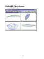


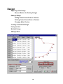
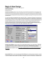

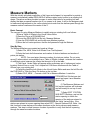
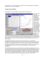
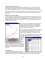
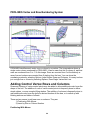


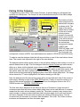
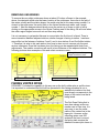


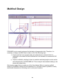


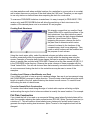


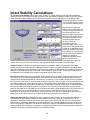
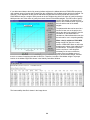
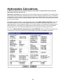

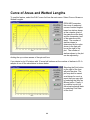
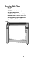

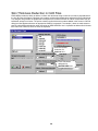
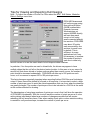


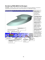
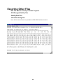
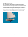


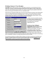
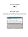


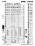


![United StiltBS Patent [19] [11] Patent Number: 5,025,556](http://vs1.manualzilla.com/store/data/006008181_1-2c5f49b6565f7d3a6ea1501cb683eb1f-150x150.png)