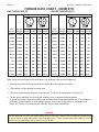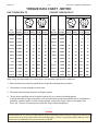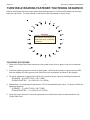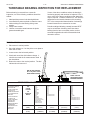
1
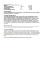
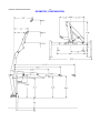
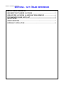
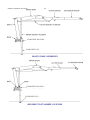
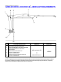
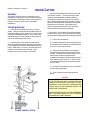
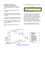
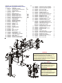
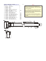
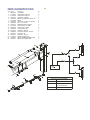
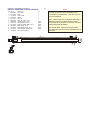
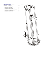
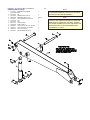
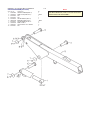
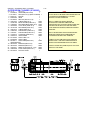
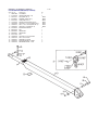
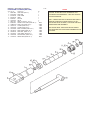
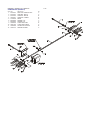
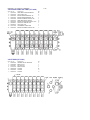
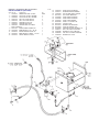
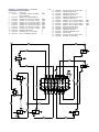
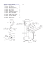
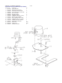
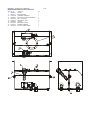
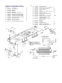
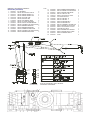
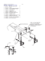
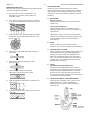
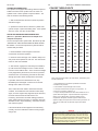
00005217:99900758: 20120417 Model 5217 Crane Volume 2 - PARTS AND SPECIFICATIONS Section Section Section Section 1 2 3 4 SPECIFICATIONS CRANE REFERENCE REPLACEMENT PARTS GENERAL REFERENCE IOWA MOLD TOOLING CO., INC. BOX 189, GARNER, IA 50438-0189 TEL: 641-923-3711 MANUAL PART NUMBER 99900758 Iowa Mold Tooling Co., Inc. is an Oshkosh Corporation company. 00005217:99900758: -------- REVISIONS LIST DATE 20001102 20030109 LOCATION 2-5 3-9 3-10 3-22,23 3/25 3-27 3-20,21 3-19 1-3,5 20030327 3-9,10 20040527 20051107 3-10,12 3-4-6,10-15 20060616 20061020 20070816 3-4,9,11 1-1, 3-3 3-4, 17,23 20071129 20081104 20100322 3-18 3-18 3-4 3-18,23 20120104 20120417 THROUGHOUT 3-12 20010430 20010523 20011204 20020318 DESCRIPTION OF CHANGE REV SPL ECN8615-41710920-CHG INNER CYL PN REPLACE INNER CYL ASM (NEW CBAL VALVE) REPLACED 77041014 WITH 77041345 TOGGLE SWITCH ADDED #5 AND #15; REVISED #6 QTY 8 WAS 12 ECN 8834 - ADDED LIGHT KIT OPTION RMV HYDRAULIC SHUTDOWN SYSTEM ECN 8886 - ADDED CAP OVERLOAD SYSTEM - 2800 PSI ECN 9066 - CHANGES TO HOOK APPROACH - HORIZONTAL WAS 2-9”; CHANGED TO 2’-11”. VERTICAL WAS 7’-2”; CHANGED TO 7’-2.5” ECN 9130 - CHANGED INNER BOOM ASM FROM 41710920 TO 41718078 AND INNER BOOM CYL FROM 3B270000 TO 51718058 ECN 9468, 9501 - ROD CHANGE ON 51718058, 3C180920 ECN 9832 - CYLINDER 71411814 REPL. 3B221850; 71411815 REPL 3C180920; 71411816 REPL 51718058 ECN 9832-2 - REVERSED CYLINDER CHANGE NEW OWNERSHIP STATEMENT; UPDATED SERIAL TAG LOCATION INFO. ECN 10539 - LONGER NYLOC NUTS ON 31713709, 41712219; ECN 10523 - CLAMP 72661642 WAS 72066516 ECN 10629 - UPDATED DRAWING FOR 91708398 ECN10762 - CHANGE FROM 8-SECTION TO 6-SECTION VALVEBANK, REVISE FUNCTION LAYOUT ECN 10767 - 71056627 IN 41712219 WAS 71056361 ECN 11134-2 - 91708398 - VB 73734514 WAS 73734071 ECN 10779 - REV 91708398, 31713709 ECN 11628 - UPDATED STABILIZER WORDING, ADDED LEVELS, STABILIZER DEPLOY DECALS ECN 11616 - UPDATED 3C180920 CYLINDER 00005217:99900758: 19980826 INTRODUCTION This volume deals with information applicable to your particular crane. For operating, maintenance and repair instructions, refer to Volume 1, OPERATION, MAINTENANCE AND REPAIR. We recommend that this volume be kept in a safe place in the office. This manual is provided to assist you with ordering parts for your IMT truck-mounted articulating crane. It also contains additional instructions regarding your particular installation. It is the user’s responsibility to maintain and operate this unit in a manner that will result in the safest working conditions possible. Warranty of this unit will be void on any part of the unit subjected to misuse due to overloading, abuse, lack of maintenance and unauthorized modifications. No warranty - verbal, written or implied - other than the official, published IMT new machinery and equipment warranty will be valid with this unit. In addition, it is also the user’s responsibility to be aware of existing Federal, State and Local codes and regulations governing the safe use and maintenance of this unit. Listed below is a publication that the user should thoroughly read and understand. ANSI/ASME B30.22 ARTICULATING BOOM CRANES The American Society of Mechanical Engineers United Engineering Center 345 East 47th Street New York, NY 10017 Three means are used throughout this manual to gain the attention of personnel. They are NOTE’s, CAUTION’s and WARNING’s and are defined as follows: NOTE A NOTE is used to either convey additional information or to provide further emphasis for a previous point. CAUTION A CAUTION is used when there is the very strong possibility of damage to the equipment or premature equipment failure. WARNING A WARNING is used when there is the potential for personal injury or death. Treat this equipment with respect and service it regularly. These two things can add up to a safer working environment. Read and familiarize yourself with the IMT OPERATOR’S CRANE SAFETY MANUAL before operating or performing any maintenance on your crane. 00005217:99900758: 20000801 NOTES 00005217:99900758: 19981023 1-1 SECTION 1. 5217 CRANE SPECIFICATIONS GENERAL SPECIFICATIONS ..................................................................................... 3 PERFORMANCE CHARACTERISTICS ...................................................................... 4 POWER SOURCE......................................................................................................... 4 CYLINDER HOLDING VALVES ................................................................................... 4 ROTATION SYSTEM .................................................................................................... 4 HYDRAULIC SYSTEM ................................................................................................. 4 GEOMETRIC CONFIGURATION .................................................................................. 5 CAPACITY CHART ...................................................................................................... 6 MINIMUM CHASSIS SPECIFICATIONS ...................................................................... 7 00005217:99900758: 19981023 1-2 NOTES 00005217:99900758: 20120104 1-3 5217 CRANE SPECIFICATIONS GENERAL SPECIFICATIONS *CRANE RATING (ANSI B30.22) 52300 ft-lbs *MAXIMUM CRANE RATING 52300 ft-lbs HORIZONTAL REACH from centerline of rotation 17'-5'’ HYDRAULIC EXTENSION 48'’ MANUAL EXTENSION None VERTICAL REACH from mounting surface 24'-1'’ VERTICAL REACH from ground / 40'’ frame ht. 27'-5'’ CRANE WEIGHT 2890 lbs STABILIZER SPAN 12'-4'’ STABILIZER PADS 12'’ x 12'’ CRANE STORAGE HEIGHT from mounting surface 7'-0'’ CRANE STORAGE HEIGHT from ground / 40'’ frame ht. 10'-4'’ **MOUNTING SPACE REQUIRED 28'’ ROTATIONAL TORQUE 7800 ft-lbs OPTIMUM PUMP CAPACITY 9 U.S. GPM SYSTEM OPERATING PRESSURE 2500 PSI OIL RESERVOIR CAPACITY 17 U.S. Gallons HOOK APPROACH - HORIZONTAL from centerline of rotation 2'-11'’ HOOK APPROACH - VERTICAL from mounting surface 7'-2-1/2'’ * Maximum Crane Rating (ft-lbs) is defined as that rated load (lbs) which when multiplied by its respective distance (ft) from centerline of rotation gives the greatest ft-lb value. ANSI B30.22 Crane Rating (ft-lbs) = With all extensions retracted and inner plus outer boom in a horizontal position, rated load (lbs) X respective distance (ft) from centerline of rotation = nominal ft-lb value. ** Allow an additional 5'’ between the cab and crane base for swing clearance. IOWA MOLD TOOLING CO., INC. BOX 189, GARNER, IA 50438-0189 TEL: 641-923-3711 FAX: 641-923-2424 00005217:99900758: 20120104 1-4 PERFORMANCE CHARACTERISTICS ROTATION: INNER BOOM ELEVATION: OUTER BOOM ARTICULATION: EXTENSION BOOM: VERTICAL STABILIZER STROKE: 450° -49° to +77° 139° 48'’ 24'’ 30 seconds 24 seconds 21 seconds 7 seconds 6 seconds POWER SOURCE Integral-mounted hydraulic pump and PTO application. Other standard power sources may be utilized minimum power required is 15 horsepower. CYLINDER HOLDING VALVES The holding sides of all standard cylinders are equipped with integral-mounted holding or counterbalance valves to prevent sudden cylinder collapse in case of hose or other hydraulic failure. The stabilizer cylinders have positive, pilot-operated holding valves that open only on command.The inner cylinders have single pilot-operated counter balance valves while the outer and extension boom cylinders have double counter-balance valves. The counter-balance valve serves several functions. First, it is a holding valve. Secondly, it is so constructed that it will control the lowering function and allow that motion to be feathered while under load. Finally, if a hose breaks, the only oil loss will be that in the hose. ROTATION SYSTEM Rotation of the crane is accomplished through a turntable bearing, powered by a high torque hydraulic motor through a ring and pinion type spur gear train. Total gear reduction is 39.61 : 1. HYDRAULIC SYSTEM The hydraulic system is an open centered, full pressure system, requiring 9 GPM optimum oil flow, at 2500 PSI. Eight-spool, stack-type control valve, six of which are used for the standard crane and the remaining two are plugged, but easily adapted for additional optional features. Dual operational handles for six functions are located at both sides of crane for convenient operation. System includes hydraulic oil reservoir, suction-line strainer, pump, 8-section control valve, return-line filter and all hoses and fittings. IMT reserves the right to change specifications and design without notice. 00005217:99900758: 20030109 1-5 GEOMETRIC CONFIGURATION 2’-11” 7’-2.5” 00005217:99900758: 20000630 1-6 641-923-3711 00005217:99900758: 20000906 1-7 MINIMUM CHASSIS SPECIFICATIONS FOR STANDARD 5217 CRANE Crane Mount Behind Cab Crane Working Area 360° Chassis Style Conventional Cab Front Axle Rating (GAWR) 7000 lbs Rear Axle Rating (GAWR) Single Axle 14,000 lbs Wheelbase 171" Cab-to-axle 102" Outigger Width Required 12'-4" RBM Frame Section Modulus Frame Yield Strength 720,000 in-lbs 14.4 cubic inches 50,000 psi Minimum Finished Unit Weight To Maintain Vehicle Stability Front Axle Rear Axle Total Finished Unit Wt. * 4900 lbs * 5400 lbs 10300 lbs * Allows lifting full capacity load in a 360° arc when crane is installed immediately behind the cab. Great care should be taken when swinging the load from rear of vehicle to front of vehicle since the front axle springs will compress, thus affecting the levelness of the vehicle. NOTES: 1. GAWR means Gross Axle Weight Rating and is dependent on all components of the vehicle such as axles, tires, wheels, springs, brakes, steering and frame strength meeting the manufacturer’s recommendations. Always specify GAWR when purchasing a truck. 2. Minimum axle requirements may increase with use of diesel engines, longer wheelbase or service bodies. Contact the factory for further information. 3. Weight distribution calculations are required to determine final axle loading. 4. All chassis and crane combinations must be stability tested to ensure stability per ANSI B30.22 00005217:99900758: 20000630 1-8 IOWA MOLD TOOLING CO., INC. BOX 189, GARNER, IA 50438-0189 TEL: 641-923-3711 FAX: 641-923-2424 00005217:99900758:19981023 2-1 SECTION 2. 5217 CRANE REFERENCE MAJOR CRANE ASSEMBLIES .................................................................................. 3 WELDMENT PART NUMBER LOCATIONS ............................................................... 3 GREASE ZERK LOCATIONS & LUBRICANT REQUIREMENTS .............................4 RECOMMENDED SPARE PARTS LIST ...................................................................... 5 INSTALLATION ............................................................................................................ 7 CRANE MOUNTING ....................................................................................................7 HYDRAULIC INSTALLATION ..................................................................................... 8 00005217:99900758: 19981023 2-2 NOTES 00005217:99900758: 20120104 2-3 STABILIZER HOUSING STABILIZER LEG MAJOR CRANE ASSEMBLIES STABILIZER HOUSING STABILIZER LEG WELDMENT PART NUMBER LOCATIONS 00005217:99900758: 19940415 2-4 GREASE ZERK LOCATIONS & LUBRICANT REQUIREMENTS ITEM 1. 2. 3. 4. 5. 6. 7. 8. LOCATION DESCRIPTION DRIVE GEAR GREASE EXTENSION TURNTABLE/BEARING GREASE EXTENSION *ROTATE CRANE WHILE GREASING PINION GEAR MAST/INNER BOOM HINGE PIN OUTER CYLINDER BASE INNER CYLINDER ROD INNER BOOM/OUTER BOOM HINGE PIN OUTER CYLINDER ROD LUBRICANT FREQUENCY SHELL ALVANIA 2EP OR WEEKLY SHELL RETINAX “A” NOTE: All application points must be greased weekly under normal work loads and moderate weather conditions. Under severe operating conditions, lubrication should be performed more frequently. See Volume 1; Operation, Maintenance and Repair for additional lubrication requirements. 00005217:99900758: 20120104 2-5 RECOMMENDED SPARE PARTS LIST 1 YEAR SUPPLY 5217 CRANE FOR MANUAL: 99900758 This spare parts list does not necessarily indicate that the items can be expected to fail in the course of a year. It is intended to provide the user with a stock of parts sufficient to keep the unit operating with the minimal down-time waiting for parts. There may be parts failures not covered by this list. Parts not listed are considered as not being Critical or Normal Wear items during the first year of operations and you need to contact the distributor or manufacturer for availability. SHELF ASSEMBLY LIFE ORDER DESIGNATION ITEM NO. PART NO. DESCRIPTION QTY CODE (MO) QTY 41712219.01.19960918 3B221850.01.19950327 3B220850.01.19940417 41710870.01.19950426 41710920.01.19940417 3B270000.01.20001102 41712218.01.19940415 3C180920.01.19940415 41708396.01.19940415 3B077880.01.19940415 BASE & MNL STABILIZER ASM 9 60020115 BUSHING 10 60020116 BUSHING 11 60020187 BUSHING 12 60020188 BUSHING 30 71056265 PINION GEAR 32 7Q072112 O-RING 54 73054538 COUNTERBALANCE VALVE POWER DOWN STABILIZER CYLINDER 5 73054004 LOCKING HOLDING VALVE 9 9B101214 SEAL KIT POWER OUT STABILIZER CYLINDER 13 9B050608 SEAL KIT MAST ASM 2 7BF81520 BUSHING INNER BOOM ASM 4 7BF81220 BUSHING INNER BOOM CYLINDER 3 6I035125 PISTON 4 6H035025 HEAD 5 9C142020 SEAL KIT 16 73054887 COUNTERBALANCE VALVE 20 7BF81020 BUSHING OUTER BOOM ASM 6 7BF81220 BUSHING OUTER BOOM CYLINDER 3 6I045143 PISTON 4 6H045030 HEAD 5 9C182423 SEAL KIT 15 73054242 COUNTERBALANCE VALVE 19 7BF81220 BUSHING 20 7BF81520 BUSHING EXTENSION BOOM ASM 12 60030064 WEAR PAD 13 60030067 WEAR PAD EXTENSION CYLINDER 4 6H025015 HEAD 5 6I025087 PISTON 6 73054304 COUNTERBALANCE VALVE 7 9B101214 SEAL KIT 1 1 1 1 1 2 2 W W W W W W C 2 2 C W 2 W 2 W 12 W 1 1 1 1 4 W W W C W 4 W 1 1 1 1 2 2 W W W C W W 1 1 W W 1 1 2 1 W W C W 00005217:99900758: 19980127 2-6 NOTES 00005217:99900758: 19940415 2-7 INSTALLATION GENERAL This section contains specific instructions for the installation of your crane. Prior to installing the crane and hydraulic components, make sure the chassis is ready to receive the crane (refer to VOLUME 1, Installation). CRANE MOUNTING 1. See SPECIFICATIONS in Section 1 for crane weight. Using an overhead hoist and fabric slings of adequate capacity, lift the crane about a foot to see if the crane is adequately balanced. If not, lower hoist and adjust slings. Re-check balance and re-position crane until mounting surface is level. 2. Install the truck frame support so that the tiedown studs pass through the supports (figure below). Cut the support to the inside dimensions of the truck frame. Allow about 1/16" extra. Grind the end of the support to fit inside the frame channel. Use a hammer to drive it into position if necessary. 3. Allow sufficient clearance between the cab and crane base, at least 5". Position the crane on the chassis per the applicable installation drawing, centering the mounting slots over the truck frame rails. While holding crane with hoist, start mounting hardware per figure below. Note position of support weldments on truck frame. Hand tighten nuts. Observe underside of crane base. No clearance between base and frame bars is allowed. 4. Torque the 1"-8 UNC Grade 5 mounting hardware to 442 ft-lbs (62 kg-m). When torquing the mounting hardware the following precautions must be followed: A. Never use lock washers. B. Hardened washers must be used, and under the turning element, whether the turning element is the nut or the head of the bolt. C. Torque values specified are with residual oils or without special lubricants applied to the threads. If special lubricants are used, such as Never-Seize compound graphite and oil, molybdenum disulphite collodial copper or white lead, reduce torque values 10%. Torque values for threaded fasteners are not affected with the use of Loctite. D. Do not use rusty fasteners, the rust will alter torque values significantly. E. Touch-up paint around mounting anchor plates. CAUTION DO NOT ATTEMPT TO APPLY THE SAME TORQUE TO THE TIE ROD AND SELF-LOCKING NUTS AS SHOWN IN THE TORQUE DATA CHART. DO NOT EXCEED 442 FT. LBS. (62 KG-M). EXCEEDING THIS TORQUE VALUE COULD DAMAGE EITHER THE CHASSIS OR CRANE BASE. POWER WRENCHING IS NOT RECOMMENDED UNTIL THE LEAD THREAD OF THE NUT INSERT IS ENGAGED BY HAND TURNING. CRANE INSTALLATION 00005217:99900758: 19940415 2-8 7. Open the gate valve at the suction-line filter. HYDRAULIC INSTALLATION To install the hydraulic hoses, fittings, etc.: 1. Install the hydraulic reservoir on the crane base. 2. Plumb the suction-line filter as shown in figure below. 3. Install the 1-1/4" suction hose between the suction-line filter and the pump inlet. Tighten the hose clamps. 4. Install the 1/2" pressure hoses between the pump outlet and the inlet port on the valve bank. 5. Install the return filter and gate valve on the reservoir. Install the hose between the valve bank and return filter. 6. Fill the hydraulic reservoir to the “FULL” mark. CAUTION FAILURE TO OPEN THE GATE VALVE WILL RESULT IN A DRY RUNNING PUMP WHICH MAY DAMAGE THE PUMP. 8. Open the return gate valve. 9. Start the vehicle’s engine and engage the PTO. Allow the system to run for about five minutes and then check the vacuum gauge on the suction-line filter (it should read 8" mercury or less). If the vacuum reading is too high, check to make certain that the gate valve is opened completely. If the valve is fully opened, check for a collapsed or restricted suction line. 10. Cycle all hydraulic functions. Check for leaks, and refill the reservoir if necessary. HYDRAULIC INSTALLATION 00005217: 99900758:20011204 3-1 SECTION 3. REPLACEMENT PARTS 5217 CRANE PARTS INFORMATION ................................................................................................. 3 GENERAL ..................................................................................................................... 3 CRANE IDENTIFICATION ............................................................................................ 3 SERIAL NUMBER PLACARD ...................................................................................... 3 CYLINDER IDENTIFICATION ....................................................................................... 3 WELDMENT IDENTIFICATION .................................................................................... 3 ORDERING REPAIR PARTS ........................................................................................ 3 CYLINDER PART NUMBER LOCATION ..................................................................... 3 BASE & MNL STABILIZER ASM (41712219) ............................................................... 4 PWR DN STABILIZER CYLINDER (3B221850) ........................................................... 5 PWR OUT STABILIZER KIT (31712253) ...................................................................... 6 PWR OUT STABILIZER CYLINDER (3B220850) ........................................................ 7 MAST ASM (41710870) ................................................................................................. 8 INNER BOOM (41718078) ............................................................................................ 9 INNER BOOM CYLINDER (51718058) ...................................................................... 10 OUTER BOOM ASM (41712218) ................................................................................ 11 OUTER CYLINDER (3C180920) ................................................................................ 12 EXTENSION BOOM ASM (41708396) ........................................................................ 13 EXTENSION CYLINDER (3B077880) ........................................................................ 14 CONTROL KIT (90704417) ......................................................................................... 15 VALVEBANK ASM-8 SECT MNL (51710944) ............................................................ 16 VALVE BANK (70731499) .......................................................................................... 16 INSTALLATION KIT (93704355) ................................................................................. 17 HYDRAULIC KIT (91708398) ..................................................................................... 18 BEACON LIGHT KIT-LOW MOUNT (51710948) ........................................................ 19 BEACON LIGHT KIT-HIGH MOUNT (51708392) ....................................................... 20 RESERVOIR ASM-15.5 GAL (70732573) ................................................................... 21 HYDRAULIC SHUTDOWN KIT (31713709) ............................................................... 22 DECAL KIT (95712259) .............................................................................................. 23 OPTION - LIGHT KIT (31717218) ............................................................................... 24 00005217: 99900758:19981023 3-2 NOTES 00005217: 99900758.01.20061020 3-3 PARTS INFORMATION GENERAL CYLINDER IDENTIFICATION This section contains the exploded parts drawings and accompanying parts lists for the assemblies used on this crane. These drawings are intended to be used in conjunction with the instructions found in the REPAIR section in Volume 1. For optional equipment such as winches and remote controls, refer to the appropriate service manual. To insure proper replacement parts are received, it is necessary to specify the complete number/letter sequence for any part requested. Part numbers may be cross checked by comparing the stamped identification on the cylinder case (see figure below) against the information contained in the service manual. You must include the part number stamped on the cylinder case when ordering parts. WARNING DO NOT ATTEMPT TO REPAIR ANY COMPONENT WITHOUT READING THE INFORMATION CONTAINED IN THE REPAIR SECTION IN VOLUME 1. PAY PARTICULAR ATTENTION TO STATEMENTS MARKED WARNING, CAUTION, OR NOTE IN THAT SECTION. FAILURE TO COMPLY WITH THESE INSTRUCTIONS MAY RESULT IN DAMAGE TO THE EQUIPMENT, PERSONAL INJURY, OR DEATH. CRANE IDENTIFICATION Every IMT crane has an identification placard (see figure) attached to the inner boom, mast, or crane base. When ordering parts, communicating warranty information, or referring to the unit in correspondence, always include the serial number and model numbers. All inquiries should be addressed to: Iowa Mold Tooling Co., Inc. Box 189, Garner, IA 50438-0189 Telephone: 641-923-3711 Technical Support Fax: 641-923-2424 WELDMENT IDENTIFICATION Each of the major weldments - base, mast, inner boom, outer boom, extension boom and stabilizer weldments bear a stamped part number. Any time a major weldment is replaced, you must specify the complete part number as stamped on the weldment. The locations of the part numbers are shown in Section 2. ORDERING REPAIR PARTS When ordering replacement parts: 1. Give the model number of the unit. 2. Give the serial number of the unit. 3. Specify the complete part number. When ordering cylinder parts, or one of the main weldments, always give the stamped part number. 4. Give a complete description of the part. 5. Specify the quantity required. IOWA M OLD TOOLING CO., INC. BOX 189, GARNER, IA 50438-0189 MODEL NUMBER SERIAL NUMBER MFG DATE SERIAL NUMBER PLACARD CYLINDER PART NUMBER LOCATION CYLINDER PART NUMBER LOCATION 00005217: 41712219.01.REV. M 20120104 3-4 BASE & MNL STABILIZER ASM (41712219) ITEM PART NO. DESCRIPTION QTY 1. 2. 3. 5. 7. 8. 9. 10. 11. 12. 13. 14. 15. 16. 17. 18. 19. 20. 21. 22. 23. 24. 25. 26. 27. 28. 29. 30. 31. 33. 34. 35. 36. STABILIZER CYLINDER INSTRUCTIONS, HYD SHUTDOWN RESERVOIR ASM SLIDING STOP BLOCK T-PIN BASE (INCL:9-13) BUSHING (PART OF 8) BUSHING (PART OF 8) BUSHING (PART OF 8) BUSHING (PART OF 8) DRIVE GEAR (PART OF 8) STABILIZER ARM STABILIZER LEG GREASE EXTENSION GREASE EXTENSION HOSE CLAMP PINION COVER SPRING GREASE PLATE ROLLER ACCESS COVER STUD 1/2-13 X 2 PIN PINION SPACER PIN GEAR GUARD INTERMEDIATE GEAR PINION GEAR TURNTABLE GEAR BEARING COUPLING 1/8NPT ZERK 1/8NPT CAP SCR 1/4-20X3/4 HHGR5 CAP SCR 3/8-16X3 HHGR5 2 1REF 1 1 2 1 1REF 1REF 1REF 1REF 1REF 2 2 1 1 2 1 2 1 4 1 2 4 1 2 1 1 1 1 2 3 2 2 3B221850 99903611 70732573 71145016 52070138 52712217 60020115 60020116 60020187 60020188 71056011 52712252 52705871 53000714 53000717 60107648 60010235 60010351 60010844 60030053 60102767 60106032 60106314 60106886 60106968 60102769 71056264 71056265 71056627 72053301 72053508 72060002 72060054 37. 38. 39. 40. 41. 42. 43. 44. 45. 46. 47. 48. 49. 50. 51. 52. 53. 55. 56. 58. 59. 60. 61. 64. 65. 66. 67. 68. 69. 70. 72060092 72060102 72060833 72062080 72062103 72062107 72063002 72053281 72063027 72063039 72063049 72063053 72063116 72066095 72066178 72060207 73540004 73051004 73054538 72060738 7Q072112 5V151830 72066125 72066185 72060046 72063003 60108883 70058060 72531826 72060023 72063050 60119748 72060006 72063001 72062104 CAP SCR 1/2-13X1-1/4 HHGR5 CAP SCR 1/2-13X5-1/2 HHGR5 SCR 5/16-18X3/4 HH SLFTPG NUT 1/2-13 LOCK NUT 3/8-16 LOCK NUT 1/2-13 CTR LOCK WASHER5/16 WRT STREET ELBOW 1/8NPT MACH BUSHING 5/8X14GA NR MACH BUSHING 2X10GA NR WASHER 1/4 LOCK WASHER 1/2 LOCK WASHER 3/4 FLAT HARD RETAINING RING 2 EXT STD COTTER PIN 1/8X1 CAP SCR 3/4-10X3 HHGR8 HYD MOTOR (FROM 5-15-98) HYD MOTOR (TO 5-15-98) C’BALANCE VALVE (TO 5-15-98) CAP SCR (TO 5-15-98) O-RING (TO 5-15-98) MOTOR BLOCK (TO 5-15-98) RETAINING RING 1 EXT HD COTTER PIN .16X1 CAP SCR 3/8-16X1 HHGR5 WASHER 3/8 WRT CHAIN COLD SHUT LINK REDUCER BUSHING 1/4-1/8NPT CAP SCR 5/16-18X3/4 HHGR5 WASHER 5/16 LOCK GUARD-CTRL HANDLE CAP SCR 1/4-20X1-1/2 HHGR5 WASHER 1/4 WRT NUT 1/4-20 LOCK 2 4 2 2 8 4 2 1 2 1 2 2 20 1 8 20 1 1 2 4 2 1 4 2 4 10 2 2 1 2 2 2 8 16 8 WARNING ANYTIME A GEAR-BEARING BOLT IS REMOVED, IT MUST BE REPLACED WITH A NEW BOLT OF THE IDENTICAL GRADE AND SIZE. FAILURE TO REPLACE GEAR-BEARING BOLTS MAY RESULT IN BOLT FAILURE DUE TO METAL FATIGUE, CAUSING SERIOUS INJURY OR DEATH. NOTE APPLY MOBILTAC 375NC LUBRICANT (OR EQUIVALENT) TO THE EXTERNAL TEETH OF THE TURNTABLE BEARING AND PINION GEAR. NOTE INSTALL 70399271 - DECAL-FULLY DEPLOYED - ON TOP OF STABILIZER BEAMS WHEN BEAMS ARE FULLY EXTENDED. DECAL MUST BE VISIBLE. 00005217: 3B221850.01.19950327 3-5 PWR DN STABILIZER CYLINDER (3B221850) ITEM PART NO DESCRIPTION 1. 2. 3. 4. 5. 6. 7. 8. 9. 10. 11. 12. 13. 14. 15. 16. 17. 18. CASE (INCL:6) ROD PISTON HEAD LOCKING/ HOLDING VALVE PLUG 1/8NPT (PART OF 1) STOP TUBE CAP SCR 1/4-20 X 1 1/4 SH SEAL KIT (INCL:10-18) O-RING (PART OF 9) SEAL, PISTON (PART OF 9) LOCK RING SEAL (PART OF 9) WEAR RING (PART OF 9) WAFER LOCK (PART OF 9) O-RING (PART OF 9) BACK-UP RING (PART OF 9) ROD SEAL (PART OF 9) ROD WIPER (PART OF 9) 4B221850 2G221850 6I025087 6H025015 73054004 7PNPXT02 6C150015 72060708 9B101214 7Q072137 7T66P025 7T61N087 7T2N8015 6A025015 7Q072228 7Q10P228 7R546015 7R14P015 QTY 1 1 1 1 1 3REF 1 6 1 1REF 1REF 1REF 1REF 1REF 1REF 1REF 1REF 1REF NOTE IT IS RECOMMENDED THAT ALL COMPONENTS OF THE SEAL KIT BE REPLACED WHENEVER THE CYLINDER IS DISASSEMBLED. THIS WILL REDUCE FUTURE DOWNTIME. APPLY “LUBRIPLATE #630-2” MEDIUM HEAVY,MULTIPURPOSE LUBRICANT OR EQUIVALENT TO ALL PISTON AND HEAD GLANDS, LOCK RING AND ROD THREADS BEFORE ASSEMBLY. USE “NEVER-SEEZ” OR EQUIVALENT BETWEEN THE HEAD AND THE CASE WHEN ASSEMBLING THE CYLINDER. 00005217: 31712253.01.REV B 20120104 3-6 PWR OUT STABILIZER KIT (31712253) ITEM PARTNO. DESCRIPTION 1. 2. 3. 4. 6. 7. 8. 9. 10. 11. 12. 13. 15. 16. 17. 18. 21. 22. 23. CYLINDER HOSE ASM 1/4X23 FF HOSE ASM 1/4X40 FF CONTROL HANDLE ELBOW 7/16MSTR 7/16MJIC 90° KNOB CAP SCR 1/2-13X2-1/4 HHGR5 NUT 1/2-13 LOCK ADAPTER #4MJIC #6FJIC TEE 7/16MJIC .20 TUBE COTTER PIN .09X3/4 CLEVIS PIN 5/16X1 CONTROL ROD-M COTTER PIN-SPCL SHORT PIN-SPCL VB CONTROL ROD-F DECAL-POWER OUT DECAL-WARNING STAND CLEAR DECAL-FULLY DEPLOYED 3B220850 51703590 51704280 70029451 72053758 71039096 72060928 72062080 72532707 72532768 72066168 72066338 52704745 72066336 72066337 52704744 71392277 70392864 70399271 QTY 2 2 4 2 4 2 4 4 2 2 2 2 2 1 1 1 2 2 2 DECAL PLACEMENT ITEM NO. 22 LOCATION ONE ON EACH STABILIZER 23 ON TOP OF BEAM WHEN FULLY DEPLOYED 21 AT POWER OUT CONTROLS 00005217: 3B220850.01.19940417 3-7 PWR OUT STABILIZER CYLINDER (3B220850) ITEM PART NO. DESCRIPTION QTY 1. 2. 3. 4. 5. 6. 7. 8. 9. 10. 11. 12. 13. CASE ASM ROD STOP TUBE HEAD PISTON SEAL KIT (INCL:7-12)) O-RING (PART OF 6) O-RING (PART OF 6) BACK-UP RING (PART OF 6) SEAL (PART OF 6) ROD WIPER (PART OF 6) PISTON SEAL (PART OF 6) RING, RETAINING 1 1 1 1 1 1 1REF 1REF 1REF 1REF 1REF 1REF 1 4B220850 4G115830 6C125007 6H012007 6I012050 9B050608 7Q072021 7Q072214 7Q10P214 7R100750 7R13P007 7T66P012 72066029 NOTE IT IS RECOMMENDED THAT ALL COMPONENTS OF THE SEAL KIT BE REPLACED WHENEVER THE CYLINDER IS DISASSEMBLED. THIS WILL REDUCE FUTURE DOWNTIME. APPLY “LUBRIPLATE #630-2” MEDIUM HEAVY,MULTIPURPOSE LUBRICANT OR EQUIVALENT TO ALL PISTON AND HEAD GLANDS, LOCK RING AND ROD THREADS BEFORE ASSEMBLY. USE “NEVER-SEEZ” OR EQUIVALENT BETWEEN THE HEAD AND THE CASE WHEN ASSEMBLING THE CYLINDER. 00005217: 41710870.01.19950426 3-8 MAST ASM (41710870) ITEM PART NO. 1. 2. 3. 4. 5. 6. 7. 8. 9. 52710871 7BF81520 60010118 60104539 70029119 72060931 72062103 72063119 72066340 DESCRIPTION QTY MAST (INCL:2) BUSHING (PART OF 1) HOSE CLAMP PINION COVER SERIAL NO. PLACARD CAP SCR 5/8-11X2-3/4 HHGR8 NUT 3/8-16 LOCK WASHER 5/8 FLAT HARD POP RIVET 1/8 1 2 REF 2 1 1 18 2 18 2 00005217: 41718078.01.REV. B 20060616 3-9 INNER BOOM (41718078) 1. 51718057 INNER BOOM CYLINDER (WAS 3B270000) 2. 52704342 PIN 3. 52710909 INNER BOOM (INCL:4) 4. 7BF81220 BUSHING (PART OF 3) 5. 60106331 PIN RETAINER PLATE 3-1/2" 6. 60107303 PIN 7. 60107305 PIN 8. 60010118 HOSE CLAMP 9. 72053508 ZERK 1/8 NPT 10. 72060049 CAP SCR 3/8-16X1-3/4 HHGR5 11. 72060147 CAP SCR 5/8X11X1 HHGR5 12. 72062103 NUT 3/8-16 LOCK 13. 60109337 PIN RETAINER PLATE 3" 2 1 1 12REF 4 1 2 1 1 1 7 1 3 NOTE ANYTIME THE PIN RETAINER PLATE BOLTS (ITEM 11) HAVE BEEN REMOVED, APPLY LOCTITE 262 TO THE THREADS BEFORE REASSEMBLY. NOTE CRANES WITH SERIAL NUMBERS BELOW 5271031001 USE INNER BOOM ASM 41710920 AND INNER BOOM CYLINDER NO. 3B270000. CRANES WITH SERIAL NUMBER 5271031001 AND ABOVE USE INNER BOOM ASM 41718078 AND INNER BOOM CYLINDER NO. 51718057. 00005217: 51718058.01.REV. A 20040527 3-10 NOTE IT IS RECOMMENDED THAT ALL COMPONENTS OF THE SEAL KIT BE REPLACED WHENEVER THE CYLINDER IS DISASSEMBLED. THIS WILL REDUCE FUTURE DOWNTIME. INNER BOOM CYLINDER (51718058) 1. 4B142920 CASE ASM (INCL:20 & 21) 2. 52718720 ROD ASM (INCL:19 & 20) (WAS 4H142920 ON 3B270000; 52718057) 3. 6I035125 PISTON 4. 6H035025 HEAD 5. 9C142020 SEAL KIT (INCL:6-15) 6. 7Q072338 O-RING (PART OF 5) 7. 7Q10P338 BACK-UP RING (PART OF 5) 8. 7T2N8027 WEAR RING (PART OF 5) 9. 7R546025 ROD SEAL (PART OF 5) 10. 7R14P025 ROD WIPER (PART OF 5) 11. 7Q072151 O-RING (PART OF 5) 12. 7T66P035 PISTON SEAL (PART OF 5) 13. 7T65I035 PISTON RING (PART OF 5) 14. 7T61N125 LOCK RING (PART OF 5) 15. 6A025025 WAFER LOCK (PART OF 5) 16. 73054887 VALVE 25GPM 17. 6C150025 STOP TUBE 18. 6C300025 STOP TUBE 19. 72053507 ZERK 1/4-28 (PART OF 2) 20. 7BF81020 BUSHING (PART OF 1 & 2) 21. 7PNPXT02 PLUG 1/8NPT (PART OF 1) 1 1 1 1 1 1REF 1REF 1REF 1REF 1REF 1REF 1REF 2REF 1REF 1REF 1 1 1 1REF 4REF 3REF APPLY “LUBRIPLATE #630-2” MEDIUM HEAVY,MULTIPURPOSE LUBRICANT OR EQUIVALENT TO ALL PISTON AND HEAD GLANDS, LOCK RING AND ROD THREADS BEFORE ASSEMBLY. USE “NEVER-SEEZ” OR EQUIVALENT BETWEEN THE HEAD AND THE CASE WHEN ASSEMBLING THE CYLINDER. NOTE USED ON CRANES WITH SERIAL NUMBERS 5217031001 AND ABOVE. CRANES WITH SERIAL NUMBERS BELOW 5217031001 USED CYLINDER 3B270000. 21 SAE #8 0-RING PORTS 16 19 20 20 14 13 11 12 13 3 CYLINDER DATA EXT. 9.62 SQ.IN. 4.71 GAL DRY WGT. 93 # RETR. 1.49 SQ.IN. .73 GAL BRG. SPAN: 12.93% CASE 4.00OD X 3.50ID X 45.88L ROD 2.50 X 46.44 X 1.25S TEST PSI: 3000 OPER PSI: 2300 18 17 15 1 2 4 6 7 8 9 10 Notes: 1) Apply "Never-Seez" regular grade anti-seize and lubricating compound to threads on cylinder head only. Keep away from all seals. 2) Apply "Lubriplate" 630-2 Medium Heavy, Multipurpose Lubricant to all piston, head gland, and holding valve seals, nylon lock ring, cast iron piston rings, and rod stinger threads. 00005217: 41712218.01.REV. B 20060616 3-11 OUTER BOOM ASM (41712218) ITEM PART NO. DESCRIPTION 1. 2. 3. 4. 5. 6. 7. 8. 9. 10. OUTER CYLINDER (INCL:2) ZERK 1/4-28 (PART OF 1) PIN PIN OUTER BOOM (INCL:6) BUSHING (PART OF 5) PIN RETAINER PLATE 3" ZERK 1/8 NPT CAP SCR 5/8-11X1 HHGR5 PIN 3C180920 72053507 52704340 52703767 52708394 7BF81220 60109337 72053508 72060147 52704341 QTY 1 2 REF 1 1 1 4REF 3 2 3 1 NOTE ANYTIME THE PIN RETAINER PLATE BOLTS (ITEM 9) HAVE BEEN REMOVED, APPLY LOCTITE 262 TO THE THREADS BEFORE REASSEMBLY. 00005217: 3C180920.01.REV. D 20120417 3-12 OUTER BOOM CYLINDER (3C180920) ITEM PART NO. 1. 2. 3. 4. 5. 6. 7. 8. 9. 10. 11. 12. 13. 14. 15. 16. 17. 18. 19. 20. 21. 22. 23. DESCRIPTION QTY 4C258870 CASE ASM (INCL:20-22) 1 52718647 ROD (INCL:19,21) (WAS 4H180920) 1 6I045143 PISTON 1 6H045030 HEAD 1 9C182423 SEAL KIT (INCL:6-14,18) 1 7Q072345 O-RING (PART OF 5) 1REF 7Q10P346 BACK-UP RING (PART OF 5) 1REF 7T2N8032 ROD WEAR RING (PART OF 5) 1REF 7R546030 U-CUP SEAL (PART OF 5) 1REF 7R14P030 ROD WIPER (PART OF 5) 1REF 7Q072155 O-RING (PART OF 5) 1REF 7T66P045 PISTON SEAL (PART OF 5) 1REF 7T65I045 PISTON RING (PART OF 5) 2REF 7T61N143 LOCK RING (PART OF 5) 1REF 73054242 VALVE 25GPM 2REF 6C150030 STOP TUBE 1-1/2 1 6C300030 STOP TUBE 3 1 60138277 STOP TUBE (PART OF 5) 1REF (WAS 6A025030) 7BF81220 BUSHING (PART OF 2) 2REF 7BF81520 BUSHING (PART OF 1) 2REF 72053507 ZERK 1/4-28 (PART OF 1 & 2) 2REF 7PNPXT02 PLUG 1/8NPT (PART OF 1) 2REF 60125699 PIN-LOCK TUBE 1 NOTE IT IS RECOMMENDED THAT ALL COMPONENTS OF THE SEAL KIT BE REPLACED WHENEVER THE CYLINDER IS DISASSEMBLED. THIS WILL REDUCE FUTURE DOWNTIME. APPLY “LUBRIPLATE #630-2” MEDIUM HEAVY,MULTI-PURPOSE LUBRICANT OR EQUIVALENT TO ALL PISTON, HEAD GLAND, AND HOLDING VALVE SEALS, NYLON LOCK RING, CAST IRON PISTON RINGS, AND ROD STINGER THREADS. APPLY “NEVER-SEEZ” REGULAR GRADE ANTISEIZE AND LUBRICATING COMPOUND TO CYLINDER HEAD AND CASE THREADS. ITEM #18, STOP TUBE, REPLACES 6A025030 WAFER LOCK. USE STOP TUBE INSTEAD OF WAFER LOCK WHEN RESEALING CYLINDER. PRESS LOCKING PIN (ITEM #23) INTO #15 HOLE DRILLED 0.188" DEEP. 00005217: 41708396.01.19980413 3-13 EXTENSION BOOM ASM (41708396) ITEM PART NO. DESCRIPTION 1. 2. 3. 4. 5. 6. 7. 8. 9. 10. 11. 12. 13. 14. 15. 16. 17. 18. 19. CYLINDER HOOK ASM (INCL:3-9) PIN (PART OF 2) SPACER (PART OF 2) LINK (PART OF 2) SWIVEL HOOK (PART OF 2) CAP SCR 1 1/4-7X4 (PART OF 2) NUT 1 1/4-7 LOCK (PART OF 2) HAIR PIN .19 (PART OF 2) EXTENSION BOOM PIN WEAR PAD WEAR PAD PIN CAP SCR 1/4 X 2 HH GR5 NUT 1/4-20 LOCK WASHER 1/4 LOCK MACH BUSHING 1X10GA RETAINING RING 1" HD 3B077880 51706199 52070151 60108857 60107324 71073035 72601666 72062073 72066145 52708393 60010470 60030064 60030067 60111956 72060008 72062104 72063001 72063034 72066125 QTY 1 1 1REF 1REF 2REF 1REF 1REF 1REF 1REF 1 1 1 1 1 1 1 1 2 2 00005217: 3B077880.01.19940415 3-14 EXTENSION CYLINDER (3B077880) ITEM PART NO. DESCRIPTION 1. 2. 3. 4. 5. 6. 7. 8. 9. 10. 11. 12. 13. 14. 15. 16. 17. CASE ASM (INCL:9) ROD ASM STOP TUBE HEAD PISTON VALVE SEAL KIT (INCL:8, 10-17) WAFER LOCK RING (PART OF 7) PIPE PLUG (PART OF 1) O RING (PART OF 7) O RING (PART OF 7) BACK UP RING (PART OF 7) ROD WIPER (PART OF 7) ROD SEAL (PART OF 7) LOCK RING (PART OF 7) PISTON SEAL (PART OF 7) WEAR RING (PART OF 7) 4B077880 4G077880 6C300015 6H025015 6I025087 73054304 9B101214 6A025015 7PNPXT02 7Q072137 7Q072228 7Q10P228 7R14P015 7R546015 7T61N087 7T66P025 7T2N8015 QTY 1 1 4 1 1 2 1 1REF 4 REF 1 REF 1 REF 1 REF 1 REF 1 REF 1 REF 1 REF 1REF NOTES IT IS RECOMMENDED THAT ALL COMPONENTS OF THE SEAL KIT BE REPLACED WHENEVER THE CYLINDER IS DISASSEMBLED. THIS WILL REDUCE FUTURE DOWNTIME. APPLY “LUBRIPLATE #630-2” MEDIUM HEAVY,MULTIPURPOSE LUBRICANT OR EQUIVALENT TO ALL PISTON AND HEAD GLANDS, LOCK RING AND ROD THREADS BEFORE ASSEMBLY. USE “NEVER-SEEZ” OR EQUIVALENT BETWEEN THE HEAD AND THE CASE WHEN ASSEMBLING THE CYLINDER. 00005217: 90704417.01.19940415 3-15 CONTROL KIT (90704417) ITEM PART DESCRIPTION QTY 1. 2. 3. 4. 5. 6. 7. 9. 10. 11. 12. ROD-CTRL HANDLE MTG CONTROL ROD-F CONTROL ROD-M CONTROL HANDLE KNOB SPACER 1-3/8 SPACER 1-3/4 CLEVIS PIN 5/16X1 CLEVIS PIN 5/16X3/4 COTTER PIN 3/32X3/4 WASHER 5/8 WRT 2 6 12 12 12 2 6 12 6 18 8 52704397 52704744 52704745 70029451 71039096 60030068 60030069 72066338 72661169 72066168 72063119 00005217: 51710944.01.19940929 3-16 VALVEBANK ASM-8 SECT MNL (51710944) ITEM PART NO. DESCRIPTION QTY 1. 2. 3. 4. 5. 6. 7. 8. 9. 10. 11. ADAPTER #10MSTR #6FSTR CAP 9/16JIC STL ELBOW #6MSTR #6MJIC 90° ELBOW #8MSTR #8MJIC 90° ELBOW #10MSTR #12MJIC 90° ADAPTER #4MJIC #6FJIC ELBOW 9/16MSTR 9/16MJIC XLG TEE 3/4JIC SWIVEL NUT CAP 3/4JIC STL VALVEBANK 8-SECTION ELBOW 9/16MSTR 3/4MJIC 90° 16 4 7 1 1 2 8 1 1 1 1 72532722 72532738 72053760 72053763 72053766 72532707 72532700 72532657 72532675 70731499 72053762 VALVE BANK (70731499) ITEM PART NO. 1. 2. 3. 4. 5. 6. 7. 73054490 73054488 94731681 73731576 7Q072018 7Q072021 7Q072017 DESCRIPTION QTY TANDEM VALVE SECTION END CAP LH TIE ROD KIT END CAP RH O-RING O-RING O-RING 8 1 1 1 18 9 9 00005217: 93704355.01.REV E 20070816 3-17 INSTALLATION KIT (93704355) ITEM PART NO. 1. 2. 3. 4. 5. 6. 7. 8. 9. 10. 11. 12. 13. DESCRIPTION 70732573 RESERVOIR ASM 17.3GAL 72060004 CAP SCR 1/4-20X1 HHGR5Z 72060046 CAP SCR 3/8-16X1 HHGR5Z 72062103 NUT 3/8-16 HEX NYLOC 72062104 NUT 1/4-20 HEX NYLOC 72063001 WASHER 1/4 W FLAT 72063003 WASHER 3/8W FLAT 72661642 HOSE CLAMP 1-3/4 T-BOLT (WAS 72066516) 72531427 ELBOW 3/4MPT #12MJIC 90° 72532346 BARB NIPPLE 1-1/4 1-1/4 90° 72532670 ELBOW #8MJIC #8FJIC 45° 72532834 BEAD NIPPLE 1.00MPT 1-1/4 90° 72532972 ADPTR #8MJIC #12FJIC QTY 1REF 2 4 4 2 4 8 2 4 1 1 1 1 14. 15. 16. 17. 18. 19. 20. 21. 23. 24. 25. 26. 27. 28. 30. 31. 73054129 72053141 73052000 60121443 51393468 51394360 51394916 60350060 60010354 60107478 60107829 52706660 72062141 72063066 72060002 72063049 GATE VALVE 3/4 BRASS PIPE NIPPLE 3/4XCLOSE BLK HYD FILTER 10MIC 3/4NPTF OIL FILTER BRACKET HOSE 3/4X60 #12F#12F HOSE 3/4X24 #12F#12F HOSE 1/2X99 #8F#8F HOSE 1-1/4 100R4 X 63 CLAMP PLATE WASHER-SQ TIEDOWN STUD-TIE DOWN 1X18 SUPPORT-TRACK FRAME 9-1/2 NUT 1.00-8 HEX LOCK GR5 WASHER 1.00 HI STR ZINC CAP SCR 1/4-20X3/4 HHGR5Z WASHER 1/4 LOCK 1 1 1 1 1 1 1 1 4 8 8 4 16 8 2 2 00005217: 91708398.01.REV H 20100322 3-18 HYDRAULIC KIT (91708398) ITEM PART NO. DESCRIPTION QTY 1. 73734514 1 REF 2. 3. 4. 5. 6. 7. 8. 9. 10. 11. 12. 51721343 51397467 51395306 51397447 51397446 51397475 51397470 51397463 72532358 72531205 72062103 VALVE BANK- 6 SECT 18D RADIO (WAS 73734071) HOSE KIT-5217 RADIO REMOTE HOSE-FF .38 X 30.00 (6-8) 100R17 HOSE-FF .38 X 27.00 (8-8) 100R17 HOSE-FF .38 X 121.00 (6-8) 100R17 HOSE-FF .38 X 114.00 (6-6) 100R17 HOSE-FF .38 X 226.00 (6-8) 100R17 HOSE-FF .38 X 65.00 (6-6) 100R17 HOSE-FF .38 X 51.00 (4-4) 100R17 ADPTR-M STR/M JIC 8 8 TEE-MALE JIC .75-16 .50 TUBE NUT .38-16 HEX NYLOC ZINC 1 2 REF 2 REF 2 REF 2 REF 2 REF 2 REF 2 REF 8 2 3 13. 14. 15. 16. 17. 18. 19. 20. 21. 22. 23. 24. 25. 26. 27. 28. 29. 72060048 72532353 72532722 72532790 72532700 72532351 51395870 51395200 51397468 51395705 72533663 72532657 72532665 72053763 73540061 72060008 72063049 STAB CAP SCR .38-16X 1.50 HH GR5 Z ADPTR-M STR/M JIC 6 4 ADPTR-M STR/F STR 10 6 ADPTR-M JIC/F JIC 6 8 ELBOW-M STR/90/M JIC XLG 6 6 ADPTR-M STR/M JIC 4 4 HOSE-FJ .25 X 15.00 (4-4) 100R17 HOSE-FF .38 X 12.00 (8-8) 100R17 HOSE-FF .38 X 41.00 (8-8) 100R17 HOSE-FF .38 X 20.00 (8-8) 100R17 ELBOW-M JIC/90/M JIC 8 8 TEE-SWVL NUT RUN JIC 8 ADPTR-M JIC/F JIC 4 8 ELBOW-M STR/90/M JIC 8 8 VALVE-CBAL CAP SCR .25-20X 2.00 HH GR5 Z WASHER .25 LOCK ZINC STAB 3 2 2 1 4 1 1 REF 2 REF 1 REF 1 REF 1 1 1 2 1 2 2 00005217: 51710948.01.20010430 3-19 BEACON LIGHT KIT-LOW MOUNT (51710948) ITEM PART NO. DESCRIPTION QTY 1. 2. 3. 4. 5. 6. 7. 8. 9. 10. 11. 12. 13. 14. 15. 16. DASH BRACKET BRACKET-LOW MOUNT CAP SCR 1/4-20X1 HH GR5 CAP SCR 3/8-16X1-1/2 HH GR5 NUT 1/4-20 HEX NUT 3/8-16 HEX WASHER 1/4 LOCK TERMINAL RING #10 16-14GA BEACON LIGHT-AMBER BUTT CONNECTOR 16-14GA TERMINAL RING 1/4 12-10GA TOGGLE SGL THW 8530K39 INDICATOR LIGHT-RED WIRE 14GA LOOM .31 ID WASHER 3/8 LOCK 1 1 5 2 5 2 5 3 1 1 1 1 1 18FT 18FT 2 60103464 60116337 72060004 72060048 72062000 72062002 72063049 77040000 77040013 77040048 77040053 77041345 77042001 89044001 89044056 72063051 00005217: 51708392.01.20010430 3-20 BEACON LIGHT KIT-HIGH MOUNT (51708392) ITEM PART NO. DESCRIPTION QTY 1. 2. 3. 4. 5. 6. 7. 8. 9. 10. 11. 12. 13. 14. 15. 16. DASH BRACKET BRACKET-HIGH MOUNT CAP SCR 1/4-20X1 HH GR5 CAP SCR 3/8-16X1-1/2 HH GR5 NUT 1/4-20 HEX NUT 3/8-16 HEX WASHER 1/4 LOCK TERMINAL RING #10 16-14GA BEACON LIGHT-AMBER BUTT CONNECTOR 16-14GA TERMINAL RING 1/4 12-10GA TOGGLE SGL THW 8530K39 INDICATOR LIGHT-RED WIRE 14GA LOOM .31 ID WASHER 3/8 LOCK 1 1 5 2 5 2 5 3 1 1 1 1 1 18FT 18FT 2 60103464 60112305 72060004 72060048 72062000 72062002 72063049 77040000 77040013 77040048 77040053 77041345 77042001 89044001 89044056 72063051 00005217: 70732573.01.19980722 3-21 RESERVOIR ASM-15.5 GAL (70732573) ITEM PART NO. DESCRIPTION 4. 9. 10. 11. 13. 14. 15. 18. 19. 20. COVER DIPSTICK ASM STRAINER 100MESH PLUG 3/4FPT SQHD MAGNETIC NUT 1/4-20 HEX WASHER 1/4 FLAT O-RING DIFFUSER 3/4NPT SCREEN 100MESH PLUG 3/4 SQHD STEEL (530047) (820117) 70144326 73052001 72062000 72063001 76393565 70034410 70732791 72053415 QTY 1 1 1 1 6 6 1 1 1 2 00005217: 31713709.01.REV J 20100322 3-22 HYDRAULIC SHUTDOWN KIT (31713709) ITEM PART NO. DESCRIPTION QTY 1. 2. 3. 4. 5. 6. 7. 8. 9. 10. 11. 12. 13. LIMIT SWITCH BRACKET MOUNT BRACKET WASHER .25 LOCK ZINC CAP SCR 1/4-20X3/4 HHGR5 CAP SCR 1/4-20X1-1/2 HHGR5 CAP SCR 1/4-20X2-3/4 HHGR5 CAP SCR 3/8-16X2-1/2 HHGR5 WASHER 1/4 WRT NUT 1/4-20 LOCK NUT 3/8-16 LOCK WASHER 3/8 BELLEVILLE SS 2 2 4 4 12 8 8 2 4 28 10 4 4 77041459 60120004 52713708 60120005 72063049 72060002 72060006 72060011 72060052 72063001 72062104 72062103 72063215 14. 15. 17. 20. 21. 22. 23. 24. 25. 26. 27. 77044468 72060004 72053763 89044232 89044331 77040186 89044274 77040000 73054980 60119748 51397477 28. 51395891 29. 30. 31. 32. 33. 60120093 60120153 72063003 89044188 72053764 STRAIN RELIEF 1/2 CAP SCR .25-20 x 1.00 HH GR5 Z ELBOW #8MSTR #8MJIC 90° WIRE 14GA RED LOOM TERMINAL 1/4 FSLPON 16-14GA WIRE 14GA BLK TERMINAL #10 RING 16-14GA DUMP VALVE GUARD (PART OF BASE ASM) HOSE-FZ 1/2X16 8-8 100R17 (WAS 51394918) HOSE-FF 1/2X27 8-8 100R17 (WAS 51704311) SPACER BRACKET WASHER 3/8 WRT CABLE 14AWG DUPLEX ELBOW #10MSTR #8MJIC 90° 2 4 2 5FT 7FT 4 4" 1 1 2REF 1 1 1 2 8 15FT 1 00005217: 95712259.01.20000517 3-23 DECAL KIT (95712259) 1. 2. 3. 4. 5. 6. 7. 8. 9. 10. 11. 12. 13. 14. 15. 70029251 70391583 70391612 70391613 70392108 70392109 71393822 70392213 70392524 70392813 70392814 70392815 70392864 70392865 70392866 IMT DIAMOND DECAL-SETUP/STOW INSTR DECAL-GREASE WEEKLY LH DECAL-GREASE WEEKLY RH DECAL-SUCTION LINE DECAL-RETURN LINE DECAL-5200 SERIES IDENT DECAL-CAUTION WASH/WAX DECAL-ROTATE CRANE/GREASE DECAL-DANGER ELECTROCUTION DECAL-WARNING OPERATOR DECAL-WARNING OPERATION DECAL-WARNING STAND CLEAR DECAL-DANGER ELECTROCUTION DECAL-WARNING OPER COND STABILIZER (OTHER SIDE) 2 2 4 4 1 1 2 1 1 2 2 2 2 4 2 17. 18. 19. 20. 21. 22. 23. 24. 25. 26. 27. 28. 29. 30. 31. 32. 33. 34. 70392888 70392890 70392891 70392982 71039134 71393865 71392255 71392256 71392257 71392258 71392365 70392889 70394190 70394189 70392868 70392863 70395323 72042097 DECAL-WARNING OPER RESTRICT DECAL-DANGER STOW/UNFOLD DECAL-DANGER DRIVELINE DECAL-CONTACT IMT DECAL-CAUTION OIL LEVEL PLACARD-CAPACITY DECAL-CONTROL R DECAL-CONTROL L DECAL-STAB PWR-DN R DECAL-STAB PWR-DN L DECAL-ALIGNMENT CRANE ROT DECAL-DANGER RC ELECTRO DECAL-CAUTION NOT A STEP PLACARD-OIL RECS DECAL-WARNING CR LOADLINE DECAL-DANGER HOIST PERS DECAL-ASME/ANSI B30.22 LEVEL NOTE: PLACE ITEM #34, LEVEL, ON FRONT AND SIDE OF CRANE BASE. 2 2 2 1 2 2 1 1 1 1 1 2 2 1 4 2 1 2 00005217: 31717218.01.20011127 3-24 OPTION - LIGHT KIT (31717218) ITEM PART NO. DESCRIPTION 1. 51717219 2. 3. 4. 5. 6. 7. 8. 9. 10. 11. 12. 13. 14. 15. 60107762 77040424 60103535 77041345 77044574 77044550 70394069 72063049 72063051 77040000 89044274 72060000 72060044 72062000 QTY CABLE ASM- FLOOD LIGHTS 1 GUARD 1 FLOOD-LT-COMP WORK LAMP 2 SWITCH BRACKET - 1 HOLE 1 TOGGLE SWITCH 1 CONNECTOR 2 TERMINAL-F 18-20 GA 2 SEAL CABLE CONNECTOR 4 WASHER 1/4 LOCK 2 WASHER 3/8 LOCK 2 TERMINAL, RING #10 STUD 16-14 1 WIRE-BLACK STRD TYPE 36” CAP SCR 1/4-20 X 1/2 HH GR5 2 CAP SCR 3/8-16 X 3/4 HH GR5 2 NUT 1/4-20 HEX ZINC DRILL .313" HOLE AND TAP 3/8-16 IN TOP OF INNER BOOM (2). CENTER THE LIGHT BRACKET ON THE LENGTH OF THE BOOM. CRANE INNER BOOM TO LIGHT SWITCH 14 10 2 6 7(2) 8(2) 1 6 7(2) 8(2) 1 REF TO LIGHTS GROUND "12 V" 15 9 3 4 11 12 3 5 13 20001206 4-1 SECTION 4. GENERAL REFERENCE SECTION 4. GENERAL REFERENCE INSPECTION CHECKLIST .............................................................................................. 3 WIRE ROPE INSPECTION ............................................................................................... 7 HOOK INSPECTION ......................................................................................................... 7 HOLDING VALVE INSPECTION ....................................................................................... 8 TWO BLOCK PREVENTION DEVICE INSPECTION ....................................................... 8 TORQUE DATA CHART - DOMESTIC ............................................................................. 9 TORQUE DATA CHART - METRIC ................................................................................ 10 TURNTABLE BEARING FASTENER TIGHTENING SEQUENCE ................................ 11 TURNTABLE BEARING INSPECTION FOR REPLACEMENT .................................... 12 20000710 4-2 NOTES SECTION 4. GENERAL REFERENCE 4-3 NOTICE The user of this form is responsible in determining that these inspections satisfy all applicable regulatory requirements OWNER/COMPANY SECTION 4. GENERAL REFERENCE Inspection Checklist CRANES TYPE OF INSPECTION (check one) DAILY (if deficiency found) CONTACT PERSON 1 MONTHLY CRANE MAKE & MODEL DATE INSPECTED CRANE SERIAL NUMBER HOUR METER READING (if applicable) UNIT I.D. NUMBER INSPECTED BY (print) LOCATION OF UNIT SIGNATURE OF INSPECTOR QUARTERLY ANNUAL TYPE OF INSPECTION NOTES: Daily and monthly inspections are to be performed by a “competent person”, who is capable of identifying existing and predictable hazards in the surroundings or working conditions which are unsanitary, hazardous, or dangerous to employees, and who has authorization to take prompt corrective measures to eliminate them. Quarterly and annual inspections are to be performed by a “qualified person” who, by possession of a recognized degree, certificate, or professional standing, or who by extensive knowledge, training and experience, successfully demonstrated the ability to solve/resolve problems relating to the subject matter, the work, or the project. One hour of normal crane operation assumes 20 complete cycles per hour. If operation exceeds 20 cycles per hour, inspection frequency should be increased accordingly. Consult Operator / Service Manual for additional inspection items, service bulletins and other information. Before inspecting and operating crane, crane must be set up away from power lines and leveled with stabilizers deployed according to the crane manufacturer’s directions. DAILY (D): Before each shift of operation, those items designated with a ( D) must be inspected. MONTHLY (M): Monthly inspections or 100 hours of normal operation (which ever comes first) includes all daily inspections plus items designated with an ( M). This inspection must be recorded and retained for a minimum of 3 months. QUARTERLY (Q): Every three months or 300 hours of normal operation (which ever comes first) includes all daily and monthly inspection items plus items designated with a ( Q). This inspection must be documented, maintained, and retained for a minimum of 12 months, by the employer that conducts the inspection. ANNUAL (A): Each year or 1200 hours of normal operation (which ever comes first) includes all items on this form which encompasses daily, monthly and quarterly inspections plus those items designated by ( A). This inspection must be documented, maintained, and retained for a minimum of 12 months, by the employer that conducts the inspection. = SATISFACTORY R = RECOMMENDATION (Should be considered for corrective action) NA = Not Applicable FREQUENCY ITEM D D D D D D D D D 1 2 3 4 5 6 7 8 9 D 10 D D D 11 12 13 KEY Labels Crane Controls Station Hyd System Hook Wire Rope Pins General covers. Operation Remote Ctrls Electrical Anti Two-Block or Two-Block Damage Prevention X = Deficient (Note: If a deficiency is found, an immediate determination must be made as to whether the deficiency constitutes a safety hazard and must be corrected prior to operation.) INSPECTION DESCRIPTION All load charts, safety & warning labels, & control labels are present and legible. Check all safety devices for proper operation. Control mechanisms for proper operation of all functions, leaks & cracks. Control and operator’s station for dirt, contamination by lubricants, & foreign materials. Hydraulic system (hoses, tubes & fittings) for leakage & proper oil level. Presence & proper operation of hook safety latches. Inspect for apparent deficiencies per applicable requirements and manufacturer’s specifications. Proper engagement of all connecting pins & pin retaining devices. Overall observation of crane for damaged or missing parts, cracked welds & presence of safety During operation, observe crane for abnormal performance, unusual wear (loose pins, wire rope damage, etc.). If observed, discontinue use & determine cause & severity of hazard. Operate remote control devices to check for proper operation. Operate all lights, alarms, etc. to check for proper operation. Operate anti-two-blocking or two-block prevention devices to check for proper operation. STATUS , R, X, NA REV: 11-22-11 20111122 20111122 4-4 Inspection Checklist = SATISFACTORY R = RECOMMENDATION (Should be considered for corrective action) NA = Not Applicable FREQUENCY ITEM D D 14 15 or similar. D 16 KEY SECTION 4. GENERAL REFERENCE CRANES X = Deficient (Note: If a deficiency is found, an immediate determination must be made as to whether the deficiency constitutes a safety hazard and must be corrected prior to operation.) INSPECTION DESCRIPTION Tires Check tires (when in use) for proper inflation and condition. Ground Ground conditions around the equipment for proper support, including ground settling under and conditions around and around stabilizers and supporting foundations, ground water accumulation, D Level Position The equipment for level position within tolerances specified by the equipment manufacturer’s recommendations, both before each shift and after each move and setup. 17 Operator Cab Significant cracks, breaks, or other deficiencies that would hamper the operator ’s view. Windows 18 Rails, rail stops, Rails, rail stops, rail clamps and supporting surfaces when the equipment has rail traveling. D D 19 20 Electrical D D 21 22 Other Other M M M M M 23 24 25 26 27 M M 28 29 M M M M M M 30 31 32 33 34 35 M M M M M M M M Q Q Q Q Q 36 37 38 39 40 41 42 43 44 45 46 47 48 49 50 51 52 53 54 55 56 57 58 Daily All daily inspection items. Cylinders Visual inspection of cylinders for leakage at rod, fittings & welds. Damage to rod & case. Valves Holding valves for proper operation. Valves Control valve for leaks at fittings & between sections. Valves Control valve linkages for wear , smoothness of operation & tightness of fasteners. Relief valve for proper pressure settings. General Bent, broken or significantly rusted/corroded parts. Electrical Electrical apparatus for malfunctioning, signs of apparent excess deterioration, dirt or moisture accumulation. Electrical systems for presence of dirt, moisture and frayed wires. Structure All structural members for damage. Welds All welds for breaks & cracks. Pins All pins for proper installation & condition. Hardware All bolts, fasteners & retaining rings for tightness, wear & corrosion Wear Pads Condition of wear pads. Pump & Motor Hydraulic pumps & motors for leakage at fittings, seals & between sections. Check tightness of mounting bolts. PTO Transmission/PTO for leakage, abnormal vibration & noise, alignment & mounting bolt torque. Hyd Fluid Quality of hydraulic fluid and for presence of water . Hyd Lines Hoses & tubes for leakage, abrasion damage, blistering, cracking, deterioration, fitting leakage & secured properly . Hook Load hook for abnormal throat distance, twist, wear & cracks. Wire Rope Condition of load line. Manual Presence of operator’s manuals with unit. Other Other Daily All daily inspection items. Monthly All monthly inspection items. Rotation Sys Rotation bearing for proper torque of all mounting bolts. Hardware Base mounting bolts for proper torque. Structure All structural members for deformation, cracks & corrosion. Base Stabilizer beams & legs Mast Inner boom Outer boom Extension(s) Jib boom Jib extension(s) Other Hardware Pins, bearings, shaf ts, gears, rollers, & locking devices for wear , cracks, corrosion & distortion. D Q clamps, supporting surfaces. Safety Devices Safety devices and operational aids for proper operation. Electrical apparatus for malfunctioning, signs of apparent excessive deterioration, dirt or moisture accumulation. 2 STATUS , R, X, NA 20111122 4-5 Inspection Checklist = SATISFACTORY R = RECOMMENDATION (Should be considered for corrective action) NA = Not Applicable FREQUENCY ITEM Q Q 59 60 61 62 63 64 65 66 67 68 69 70 71 72 73 74 75 76 77 KEY Hyd Lines Pumps & Motors Q 78 79 80 81 82 83 84 85 86 87 Cylinders Q Q A A A A A A A A A A A A 88 89 90 91 92 93 94 95 96 97 98 99 100 101 102 103 104 105 106 107 108 109 Winch Hyd Filters Daily Monthly Quarterly Hyd Sys Controls Valves Valves Rotation Sys Lubrication Hardware Wear Pads Loadline Q Valves SECTION 4. GENERAL REFERENCE CRANES X = Deficient (Note: If a deficiency is found, an immediate determination must be made as to whether the deficiency constitutes a safety hazard and must be corrected prior to operation.) INSPECTION DESCRIPTION Rotation bearing(s) Inner boom pivot pin(s) & retainer(s) Outer boom pivot pin(s) & retainer(s) Inner boom cylinder pin(s) & retainer(s) Outer boom cylinder pin(s) & retainer(s) Extension cylinder pin(s) & retainer(s) Jib boom pin(s) & retainer(s) Jib cylinder pin(s) & retainer(s) Jib extension cylinder pin(s) & retainer(s) Boom tip attachments Other Hoses, fittings & tubing for proper routing, leakage, blistering, deformation & excessive abrasion. Pressure line(s) from pump to control valve Return line(s) from control valve to reservoir Suction line(s) from reservoir to pump Pressure line(s) from control valve to each function Load holding valve pipe(s) and hose(s) Other Pumps & motors for loose bolts/fasteners, leaks, noise, vibration, loss of performance, heating & excess pressure. Winch motor(s) Rotation motor(s) Other Hydraulic valves for cracks, spool return to neutral, sticking spools, proper relief valve setting, relief valve failure. Main control valve Load holding valve(s) Stabilizer or auxiliary control valve(s) Other Other Hydraulic cylinders for drifting, rod seal leakage & leakage at welds. Rods for nicks, scores & dent s. Case for damage. Case & rod ends for damage & abnormal wear . Stabiliizer cylinder(s) Inner boom cylinder(s) Outer boom cylinder(s) Extension cylinder(s) Rotation cylinder(s) Jib lift cylinder(s) Jib extension cylinder(s) Other Winch, sheaves & drums for damage, abnormal wear , abrasions & other irregularities. Hydraulic filters for replacement per maintenance schedule. All daily inspection items. All monthly inspection items. All quarterly inspection items. Hydraulic fluid change per maintenance schedule. Control valve calibration for correct pressures & relief valve settings Safety valve calibration for correct pressures & relief valve settings. Valves for failure to maintain correct settings. Rotation drive system for proper backlash clearance & abnormal wear , deformation & cracks. Gear oil change in rotation drive system per maintenance schedule. Check tightness of all fasteners and bolts. Wear pads for excessive wear . Loadline for proper attachment to drum. 3 STATUS , R, X, NA 20111122 4-6 SECTION 4. GENERAL REFERENCE Deficiency / Recommendation / Corrective Action Report DATE OWNER 4 UNIT I.D. NUMBER GUIDELINES A. A deficiency (X) may constitute a hazard. X must be corrected and/or faulty parts replaced before resuming operation. B. Recommendations (R) should be considered for corrective actions. Corrective action for a particular recommendation depends on the facts in each situation. C. Corrective actions (CA), repairs, adjustments, parts replacement, etc. are to be performed by a qualified person in accordance with all manufacturer’s recommendations, specifications and requirements. NOTE: Deficiencies (X) listed must be followed by the corresponding corrective action taken (CA). X = DEFICIENCY R = RECOMMENDATION CA = CORRECTIVE ACTION TAKEN X, R, CA ITEM # EXPLANATION If additional space is required, reproduce this page and attach to this report. DATE CORRECTED 20000710 WIRE ROPE INSPECTION Wire rope with any of the deficiencies shown below shall be removed and replaced immediately . A. Corrosion can be cause for replacement. Any development of corrosion must be noted and monitored closely. B. When there are either 3 broken wires in one strand or a total of six broken wires in all strands in any one rope lay. 4-7 SECTION 4. GENERAL REFERENCE HOOK INSPECTION Hooks having any of the listed deficiencies shall be removed from service unless a qualified person approves their continued use and initiates corrective action. Hooks approved for continued use shall be subjected to periodic inspection. A. DISTORTION Bending / Twisting A bend or twist exceeding 10° from the plane of the unbent hook. Increased Throat Opening HOOK WITHOUT LATCH: An increase in throat opening exceeding 15% (Or as recommended by the manufacturer) HOOK WITH LATCH: An increase of the dimension between a fully-opened latch and the tip section of the hook exceeding 8% (Or as recommended by the manufacturer) C. When flat spots on the outer wires appear and those outside wires are less than 2/3 the thickness of the unworn outer wire. D. When there is a decrease of diameter indicating a core failure. E. When kinking, crushing, birdcaging or other distortion occurs. F. When there is noticeable heat damage (discoloration) of the rope by any means. G. When the diameter is reduced from nominal size by 1/32" or more. H. If a broken wire protrudes or loops out from the core of the rope. B. WEAR If wear exceeds 10% of the original sectional dimension. (Or as recommended by the manufacturer) C. CRACKS, NICKS, GOUGES Repair of cracks, nicks, and gouges shall be carried out by a designated person by grinding longitudinally , following the contour of the hook, provided that no dimension is reduced more than 10% of its original value. (Or as recommended by the manufacturer) (A qualified person may authorize continued use if the reduced area is not critical.) D. LATCH Engagement, Damage & Malfunction If a latch becomes inoperative because of wear or deformation, and is required for the service involved, it shall be replaced or repaired before the hook is put back into service. If the latch fails to fully close the throat opening, the hook shall be removed from service or “moused” until repairs are made. E. HOOK ATTACHMENTS & SECURING MEANS If any indication of distortion, wear, cracks, nicks or gouges are present, unless a qualified person authorizes their use. (Or as recommended by the manufacturer) 20111220 HOLDING VALVE INSPECTION The cylinders are equipped with holding valves that prevent sudden movement of the cylinder rods in the event of a hydraulic hose or other hydraulic component failure. The valve is checked in the following manner: 4-8 SECTION 4. GENERAL REFERENCE COARSE THREAD BOLTS TIGHTENING TORQUE 1. With a full rated load, extend the cylinder in question and kill the engine. 2. Operate the control valve to retract the cylinder. If the cylinder “creeps”, replace the holding valve. If the cylinder does not “creep”, the valve is serviceable. TWO BLOCK PREVENTION DEVICE INSPECTION (See Vol. 1, Operation, Maintenance and Repair for a complete description) The two block prevention system halts the “winch-up” and “extension-out” crane functions before the block contacts the sheave. The two block prevention system should be checked daily as follows: 1. Examine flexible rod and weight to insure free unrestricted mechanical operation 2. Examine cord for damage, cuts or breaks. Grasp cord and pull to check operation of cord reel. The cord should retract on reel when released. 3. Start vehicle, engage PTO and slowly winch loadline up until anti-two block weight comes in contact with the hook end of the loadline cable. At the moment the weight is fully supported by the hook end, the winch up function should become non-functioning, because the two-block damage prevention switch will stop further movement. If operation other than as described occurs, stop immediately and investigate. Failure to do so will risk damage to the cable or the crane. Then, extend the winch cable to relieve the two-block condition, and actuate the boom extend function slowly . Again, once the weight is fully supported by the hook end, the boom extend function should become nonfunctioning, because the two-block damage prevention switch will stop further movement. If operation other than described occurs, stop immediately , reverse the function, and check the system. If the anti two block function appears to be functioning normally, winch the cable down until the sensing weight swings free. SIZE (DIA-TPI) SAE J429 SAE J429 GRADE 5 GRADE 8 BOLT DIA PLAIN PLATED PLAIN PLATED (INCHES) (FT-LBS) (FT-LBS) (FT-LBS) (FT-LBS) 5/16-18 0.3125 17 13 25 18 3/8-16 0.3750 31 23 44 33 7/16-14 0.4375 49 37 70 52 1/2-13 0.5000 75 57 105 80 9/16-12 0.5625 110 82 155 115 5/8-11 0.6250 150 115 220 160 3/4-10 0.7500 265 200 375 280 7/8-9 0.8750 395 295 605 455 1-8 1.0000 590 445 910 680 1 1/8-7 1.1250 795 595 1290 965 1 1/4-7 1.2500 1120 840 1815 1360 1 3/8-6 1.3750 1470 1100 2380 1780 1 1/2-6 1.5000 1950 1460 3160 2370 When using the torque data in the charts above, the following rules should be observed. 1. Bolt manufacturer ’s particular specifications should be consulted when provided. 2. Flat washers of equal strength must be used. 3. All torque measurements are given in foot-pounds. To convert to inch-pounds, multiply by 12. 4. Torque values specified are for bolt s with residual oils or no special lubricants applied. If special lubricants of high stress ability, such as Never-Seez compound graphite and oil, molybdenum disulphite, collodial copper or white lead are applied, multiply the torque values in the charts by the factor .90. The use of Loctite does not affect the torque values listed above. WARNING Anytime a gear-bearing bolt is removed, it must be replaced with a new bolt of the identical grade and size. Once a bolt has been torqued to 75% of its proof load and then removed, the torque coefficient may no longer be the same as when the bolt was new thus giving indeterminate clamp loads af ter torquing. Failure to replace gear-bearing bolts may result in bolt failure due to metal fatique causing serious injury or DEA TH. 20000710 4-9 SECTION 4. GENERAL REFERENCE TORQUE DATA CHART - DOMESTIC FINE THREAD BOLTS SIZE (DIA-TPI) BOLT DIA (INCHES) COARSE THREAD BOLTS TIGHTENING TORQUE TIGHTENING TORQUE SAE J429 SAE J429 GRADE 5 GRADE 8 PLAIN PLATED PLAIN PLATED (FT-LBS) (FT-LBS) (FT-LBS) (FT-LBS) SAE J429 SAE J429 GRADE 5 GRADE 8 PLAIN PLATED PLAIN PLATED (FT-LBS) (FT-LBS) (FT-LBS) (FT-LBS) SIZE (DIA-TPI) BOLT DIA (INCHES) 5/16-24 0.3125 19 14 27 20 5/16-18 0.3125 17 13 25 18 3/8-24 0.3750 35 26 49 35 3/8-16 0.3750 31 23 44 33 7/16-20 0.4375 55 41 78 58 7/16-14 0.4375 49 37 70 52 1/2-20 0.5000 90 64 120 90 1/2-13 0.5000 75 57 105 80 9/16-18 0.5625 120 90 170 130 9/16-12 0.5625 110 82 155 115 5/8-18 0.6250 170 130 240 180 5/8-11 0.6250 150 115 220 160 3/4-16 0.7500 300 225 420 315 3/4-10 0.7500 265 200 375 280 7/8-11 0.8750 445 325 670 500 7/8-9 0.8750 395 295 605 455 1-12 1.0000 645 485 995 745 1-8 1.0000 590 445 910 680 1 1/8-12 1.1250 890 670 1445 1085 1 1/8-7 1.1250 795 595 1290 965 1 1/4-12 1.2500 1240 930 2010 1510 1 1/4-7 1.2500 1120 840 1815 1360 1 3/8-12 1.3750 1675 1255 2710 2035 1 3/8-6 1.3750 1470 1100 2380 1780 1 1/2-12 1.5000 2195 1645 3560 2670 1 1/2-6 1.5000 1950 1460 3160 2370 When using the torque data in the charts above, the following rules should be observed. 1. Bolt manufacturer’s particular specifications should be consulted when provided. 2. Flat washers of equal strength must be used. 3. All torque measurements are given in foot-pounds. To convert to inch-pounds, multiply by 12. 4. Torque values specified are for bolts with residual oils or no special lubricants applied. If special lubricants of high stress ability, such as Never-Seez compound graphite and oil, molybdenum disulphite, collodial copper or white lead are applied, multiply the torque values in the charts by the factor .90. The use of Loctite does not affect the torque values listed above. WARNING Anytime a gear-bearing bolt is removed, it must be replaced with a new bolt of the identical grade and size. Once a bolt has been torqued to 75% of its proof load and then removed, the torque coefficient may no longer be the same as when the bolt was new thus giving indeterminate clamp loads af ter torquing. Failure to replace gear-bearing bolts may result in bolt failure due to metal fatique causing serious injury or DEATH. 20000710 4-10 SECTION 4. GENERAL REFERENCE TORQUE DATA CHART - METRIC FINE THREAD BOLTS COARSE THREAD BOLTS TIGHTENING TORQUE SIZE (DIA-TPI) BOLT DIA (INCHES) SAE J429 GRADE 5 PLAIN PLATED (KG-M) (KG-M) TIGHTENING TORQUE SAE J429 GRADE 8 PLAIN PLATED (KG-M) (KG-M) SIZE (DIA-TPI) BOLT DIA (INCHES) SAE J429 GRADE 5 PLAIN PLATED (KG-M) (KG-M) SAE J429 GRADE 8 PLAIN PLATED (KG-M) (KG-M) 5/16-24 0.3125 3 2 4 3 5/16-18 0.3125 2 2 3 2 3/8-24 0.3750 5 4 7 5 3/8-16 0.3750 4 3 6 5 7/16-20 0.4375 8 6 11 8 7/16-14 0.4375 7 5 10 7 1/2-20 0.5000 12 9 17 12 1/2-13 0.5000 10 8 15 11 9/16-18 0.5625 17 12 24 18 9/16-12 0.5625 15 11 21 16 5/8-18 0.6250 24 18 33 25 5/8-11 0.6250 21 16 30 22 3/4-16 0.7500 41 31 58 44 3/4-10 0.7500 37 28 52 39 7/8-11 0.8750 62 45 93 69 7/8-9 0.8750 55 41 84 63 1-12 1.0000 89 67 138 103 1-8 1.0000 82 62 126 94 1 1/8-12 1.1250 123 93 200 150 1 1/8-7 1.1250 110 82 178 133 1 1/4-12 1.2500 171 129 278 209 1 1/4-7 1.2500 155 116 251 188 1 3/8-12 1.3750 232 174 375 281 1 3/8-6 1.3750 203 152 329 246 1 1/2-12 1.5000 304 228 492 369 1 1/2-6 1.5000 270 210 438 328 When using the torque data in the charts above, the following rules should be observed. 1. Bolt manufacturer’s particular specifications should be consulted when provided. 2. Flat washers of equal strength must be used. 3. All torque measurements are given in kilogram-meters. 4. Torque values specified are for bolts with residual oils or no special lubricants applied. If special lubricants of high stress ability, such as Never-Seez compound graphite and oil, molybdenum disulphite, collodial copper or white lead are applied, multiply the torque values in the charts by the factor .90. The use of Loctite does not affect the torque values listed above. WARNING Anytime a gear-bearing bolt is removed, it must be replaced with a new bolt of the identical grade and size. Once a bolt has been torqued to 75% of its proof load and then removed, the torque coefficient may no longer be the same as when the bolt was new thus giving indeterminate clamp loads af ter torquing. Failure to replace gear-bearing bolts may result in bolt failure due to metal fatique causing serious injury or DEATH. 20000710 4-11 SECTION 4. GENERAL REFERENCE TURNTABLE BEARING FASTENER TIGHTENING SEQUENCE Refer to the diagram below for proper tightening/torqueing sequence of the turntable bearing to the crane base and crane mast. The total quantity of cap screws varies dependent on crane model. 18 22 3 7 11 15 14 19 10 WARNING Number 1 can be assigned to any capscrew if the sequence remains the same in reference to number 1. 6 2 23 1 24 5 9 20 13 16 12 8 4 21 17 TIGHTENING PROCEDURE: 1. Refer to the Torque Data Chart to determine the proper torque value to apply to the size of capscrew used. 2. Follow the tightening sequence shown in the diagram. Note that the quantity of capscrews may differ from the diagram, but the sequence must follow the criss-cross pattern as shown in the diagram. 3. Torque all capscrews to approximately 40% of the specified torque value, by following the sequence. (EXAMPLE: .40 x 265 FT-LBS = 106 FT-LBS) (EXAMPLE-METRIC: .40 x 36 KG-M = 14.4 KG-M) 4. Repeat Step 3, but torqueing all capscrews to 75% of the specified torque value. Continue to follow the tightening sequence. (EXAMPLE: .75 x 265 FT-LBS = 199 FT-LBS) (EXAMPLE-METRIC: .75 x 36 KG-M = 27 KG-M) 5. Using the proper sequence, torque all capscrews to the listed torque value as determined from the Torque Data Chart. 20111220 4-12 SECTION 4. GENERAL REFERENCE TURNTABLE BEARING INSPECTION FOR REPLACEMENT Before a bearing is removed from a crane for inspection, one of the following conditions should be evident: 1. Metal particles present in the bearinglubricant. 2. Increased drive power required to rotate the crane. 3. Noise emitting from the bearing during crane rotation. 4. Rough crane rotation. 5. Uneven or excessive wear between the pinion gear and turntable gear. If none of the above conditions exists, the bearing is functioning properly and need not be replaced. But, if one or more of the above conditions exists, inspection may be required. Limits are measured in “TILT” which is dependent on the internal clearances of the bearing. TILT is the most practical determination of a bearings internal clearance once mounted on a crane. Periodic readings indicating a steady increase inTILT may be an indicator of bearing wear. Note that a bearing found to have no raceway cracks or other structural irregularities should be reassembled and returned to service. TEST PROCEDURE 1. Place crane in vertical position. 2. Set a dial indicator at 0 on the pinion cover plate at back side of mast. 3. Lower crane to the horizontal position. 4. Check and record the dial indicator change. It should not exceed the tilt measurement noted in the chart below. 5. Return the crane to the vertical position. The dial indicator should return to 0. Set up dial indicator to 0" on pinion cover at back side of mast. Lower crane to horizontal position. Read dial indicator. COMPARISON CHART - MODEL TO MEASURED TILT DIMENSION NOTE THE FIGURES LISTED IN THIS CHART ARE SERVICE GUIDELINES AND DO NOT, IN THEMSELVES, REQUIRE THAT THE BEARING BE INSPECTED. IF THERE IS REASON TO SUSPECT AN EXCESS OF BEARING WEAR AND THE MEASURED TILT DIMENSION EXCEEDS THE DIMENSION LISTED, REMOVE THE BEARING FOR INSPECTION. IMT CRANE, LOADER OR TIREHAND MODEL 1007 1014 1014A 1015 2015/2020 2109 3000 3816/3820 3016/3020 421/425 4300 5016/5020 6016/6020 TH7 BODY ROT’N TH1449 BODY ROT’N TH15B CLAMP TH2551B CLAMP TH2557A CLAMP 5200 5200R 5217 5800 7020 7025 7200 7415 9000 TH10 BODY ROT’N TH14 BODY ROT’N 16000 32018 32027 32030 T30 T40 9800 12916 13031 13034 14000 15000 18000 20017 8000L H1200 H1200RR T50 TH2551B BODY ROT’N TH2557B BODY ROT’N TH2557A BODY ROT’N BALL DIA. (REF) .875” (22mm) 1.00” (25mm) 1.18”-1.25” (30-32mm) 1.75” (44mm) TILT DIM. (A1-A2) .060” (1.524mm) .070” (1.778mm) .075” (1.905mm) .090” (2.286mm) 20000710 4-13 SECTION 4. GENERAL REFERENCE The information within this manual has been compiled and checked but errors do occur . To provide our customers with a method of communicating those errors we have provided the Manual Change Request form below . In addition to error reporting, you are encouraged to suggest changes or additions to the manual which would be of benefit to you. eW cannot guarantee that these additions will be made but we do promise to consider them. When completing the form, please write or print clearly. Submit a copy of the completed form to the address listed below . MANUAL CHANGE REQUEST PRODUCT MANUAL DATE MANUAL PART NO. SUBMITTED BY COMPANY ADDRESS CITY, STATE, ZIP TELEPHONE ERROR FOUND LOCATION OF ERROR (page no.): DESCRIPTION OF ERROR: ERROR FOUND DESCRIPTION OF ADDITION: REASON FOR ADDITION: MAIL TO: IOWA MOLD TOOLING CO., INC. BOX 189 GARNER, IA 50438-0189 ATTN: Technical Publications 20001206 4-14 SECTION 4. GENERAL REFERENCE This parts manual is provided to the user to assist in servicing the equipment. It is the property of Iowa Mold T ooling Co., Inc. and, as such, may not be reproduced either whole or in part, whether by chemical, electrostatic, mechanical or photographic means without the expressed written permission of an of ficer of Iowa Mold Tooling Co., Inc. One manual is provided with each piece o f new equipment and additional manuals may be obt ained at a nominal price. Your distributor may have access to this manual through the IMT web site at www.IMT.com. IOWA MOLD TOOLING CO., INC. BOX 189, GARNER, IA50438-0189 TEL: 641-923-3711 TECHNICAL SUPPORT FAX: 641-923-2424 www.imt.com