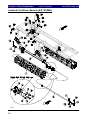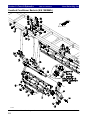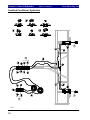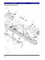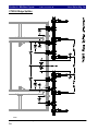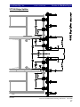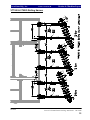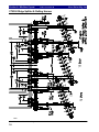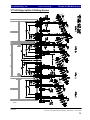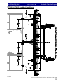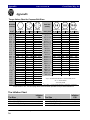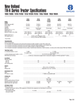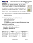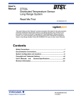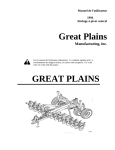
1
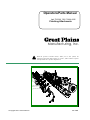
Operators/Parts Manual Verti-Till 5300, 7225, 7300 & 9225 Finishing Attachments Manufacturing, Inc. ! ©Copyright 2005 Printed 4/8/2010 Read the operator’s manual entirely. When you see this symbol, the subsequent instructions and warnings are serious - follow without exception. Your life and the lives of others depend on it! 596-156M General Information Table of Contents ► Great Plains Mfg., Inc. General Information Great Plains Manufacturing, Inc. provides this publication “as is” without warranty of any kind, either expressed or implied. While every precaution has been taken in the preparation of this manual, Great Plains Manufacturing, Inc. assumes no responsibility for errors or omissions. Neither is any liability assumed for damages resulting from the use of the information contained herein. Great Plains Manufacturing, Inc. reserves the right to revise and improve its products as it sees fit. This publication describes the state of this product at the time of its publication, and may not reflect the product in the future. Printed in the United States of America. For your convenience, record your Serial Number, Model Number and the Date Purchased in the spaces provided below. Have this information available when calling your Great Plains Authorized Dealer. Owner’s Information Name:_______________________________ Address _____________________________ City______________State ____ Zip _______ Serial Number ___________________ Model Number ___________________ Date Purchased __________________ Phone_______________________ Name of Dealership ____________________ Dealer’s Name ________________________ Address _____________________________ City______________State ____ Zip _______ Phone_______________________ Verti-Till VT5300-VT9225 Finishing Attachments 596-156M 6/30/2008 Great Plains Mfg., Inc. Table of Contents Table of Contents Using This Manual ............................................. 2 Introduction ........................................................ 2 Section 1 Safety Rules ........................................ 3 General Operation & Repair ......................... 3 Transporting ................................................. 3 Safety Decals ................................................ 3 Section 2 Assembly & Set-Up ............................ 4 Ridge Splitter Assembly ............................... 4 Rolling Harrow Assembly ............................ 5 Seedbed Conditioner to Verti-Till Attachment .............................................. 6 Section 3 Operating Instructions ...................... 8 Prior to Going to the Field ............................ 8 General Operating Instructions and In-Field Adjustments ............................... 8 Section 4 Maintenance & Lubrication ............. 9 General Maintenance .................................... 9 Lubrication ................................................... 9 Section 5 Parts & Hydraulics............................. 10 Ridge Splitter ................................................ 10 Rolling Harrow ............................................. 12 Seedbed Conditioner Frame ......................... 14 Seedbed Conditioner Baskets (S/N 1079MM-) ............................................ 16 Seedbed Conditioner Baskets (S/N 1080MM-) ............................................ 18 Seedbed Conditioner Hydraulics .................. 20 Seedbed Conditioner Transport .................... 22 Seedbed Conditioner Decals ........................ 24 6/30/2008 Section 6 Machine Layouts ............................... 26 VT5300 Ridge Splitter ................................. 26 VT7300 Ridge Splitter ................................. 27 VT5300 & VT7225 Rolling Harrow ............ 28 VT7300 & VT9225 Rolling Harrow ............ 29 VT5300 Ridge Splitter & Rolling Harrow ... 30 VT7300 Ridge Splitter & Rolling Harrow ... 31 VT5300 & VT7225 Seedbed Conditioner ... 32 VT7300 & VT9225 Seedbed Conditioner ... 33 VT5300 Ridge Splitter & Seedbed Conditioner .............................................. 34 VT7300 Ridge Splitter & Seedbed Conditioner .............................................. 35 Appendix ............................................................. 36 Torque Values for Common Bolt Sizes ....... 36 Tire Inflation Chart ...................................... 36 Verti-Till VT5300-VT9225 Finishing Attachments 596-156M 1 Using This Manual Great Plains Mfg., Inc. Table of Contents ► Using This Manual For your safety and to help in developing a better understanding of your equipment we highly recommend that you read the operator sections of this manual. Reading these sections not only provides valuable training but also familiarizes you with helpful information and its location. The parts sections are for reference only and don’t require cover to cover reading. After reviewing your manual store it in a dry, easily accessible location for future reference. Introduction This manual has been prepared to instruct you in the safe and efficient operation of your Finishing Attachment. Read and follow all instructions and safety precautions carefully. The parts on your Finishing Attachment have been specially designed and should only be replaced with genuine Great Plains parts. Therefore, should your Finishing Attachment require replacement parts go to your Great Plains Dealer. The right hand and left hand as used throughout this manual is determined by facing in the direction the machine will travel when in use unless otherwise stated. ! ! The SAFETY ALERT SYMBOL indicates that there is a potential hazard to personal safety involved and extra safety precautions must be taken. When you see this symbol, be alert and carefully read the message that follows it. In addition to design and configuration of equipment; hazard control and accident prevention are dependent upon the awareness, concern, prudence and proper training of personnel involved in the operation, transport, maintenance and storage of equipment. Verti-Till VT5300-VT9225 Finishing Attachments 596-156M 2 Watch for the following safety notations throughout your Operators Manual: !! DANGER! Indicates an imminently hazardous situation which, if not avoided, will result in death or serious injury. This signal word is limited to the most extreme situations. !! WARNING! Indicates a potentially hazardous situation which, if not avoided, could result in death or serious injury. !! CAUTION! Indicates a potentially hazardous situation which, if not avoided, may result in minor or moderate injury. It may also be used to alert against unsafe practices. Note: Indicates a special point of information which requires your attention. 6/30/2008 Great Plains Mfg., Inc. Table of Contents ► Section 1: Safety Rules Safety Rules Most accidents are the result of negligence and carelessness, usually caused by failure of the operator to follow simple but necessary safety precautions. The following safety precautions are suggested to help prevent such accidents. The safe operation of any machinery is a big concern to consumers and manufacturers. Your Finishing Attachment has been designed with many built-in safety features. However, no one should operate this product before carefully reading this Operators Manual. Transporting 1. Use good judgement when transporting tractor and implements on the highway. Always maintain complete control of the machine. 2. Use warning flags or approved warning lights at night and during other periods of poor visibility. Do your best to prevent highway accidents. 3. When in transport, use accessory lights and devices for adequate warning to operators of other vehicles and use safety hitch chain. Comply with all Federal, State and Local laws when traveling on public roads. General Operation & Repair 1. NEVER permit anyone near machinery while in operation. 4. Reduce speed of the tractor when transporting over hills or steep slopes. 2. Excessive speed can cause machine damage. 5. 3. NEVER allow anyone to be near the machine when folding wings. Reduce speed of the tractor when transporting over uneven or rough terrain. Avoid all chuck holes and washboard areas in roads. 4. Reduce speed of the tractor when transporting over uneven or rough terrain. Avoid all chuck holes and washboard areas in roads. 5. Reduce speed of the tractor when transporting over hills or steep slopes. 6. DO NOT lubricate, adjust or repair the machine while it is in operation. 7. Use "Slow Moving Vehicle" emblem for warning vehicles approaching from the rear. 8. DO NOT permit smoking, sparks, or an open flame where combustible lubricants or liquids are being used. 9. !! CAUTION! Escaping fluid under pressure can have sufficient force to penetrate the skin. Check all hydraulic lines and hoses BEFORE applying pressure. Fluid escaping from a very small hole can be almost invisible. Use paper or cardboard, NOT BODY PARTS, to check for suspected leaks. If injured, seek medical assistance from a doctor that is familiar with this type of injury. Foreign fluids in the tissue must be surgically removed within a few hours or gangrene will result. 6/30/2008 Safety Decals 1. Your Finishing Attachment come equipped with all safety decals in place. They were designed to help you safely operate your Finishing Attachment. Read and follow their directions. 2. Keep safety decals clean and legible. 3. Replace all damaged or missing safety decals. To order new safety decals go to your Great Plains Dealer and refer to the parts section for safety decal package part number. 4. Replace these decals whenever they become worn or unreadable. To instal new safety decals: a) Clean the area the decal is to be placed. b) Peel backing from the decal. Press firmly on to surface being careful not to cause air bubbles under the decal. Verti-Till VT5300-VT9225 Finishing Attachments 596-156M 3 Section 2: Assembly & Set-Up Table of Contents ► Great Plains Mfg., Inc. Assembly & Set-Up This section covers the proper assembly of the finishing attachment. The reference numbers on the figures give you an indication of the order of assembly. For a complete breakdown of any parts not shown in this assembly section, refer to Section 5, Parts & Hydraulics, starting on page 10. Refer to Section 6, page 26-35, for proper location of attachments. Go to the Appendix for proper bolt torque values. Ridge Splitter Assembly Move the machine to a safe, clean working area before proceeding. The ridge splitter assembly will come completely assembled from the factory. Start by locating the ridge splitter assembly. For ease of assembly you should use an over head hoist or fork lift to mount assemblies. Bolt the ridge splitter assembly (1) to the rear bar of the Vertitill using 3/4 x 6 x 5 5/8 u-bolts (2) and secure with lockwashers and hex nuts as shown in Figure 1. Verify placement dimensions for model of machine in the Machine Layout section and tighten bolts. Spring shank preload should be 12¼ inches as measured at spring. Figure 1 Verti-Till VT5300-VT9225 Finishing Attachments 596-156M 4 6/30/2008 Great Plains Mfg., Inc. Table of Contents ► Section 2: Assembly & Set-Up Rolling Harrow Assembly Move the machine to a safe, clean working area before proceeding. Start by Ubolting the VT rolling harrow brackets (1) to the rear bar of the Verti-till as shown in Figure 2. Use 3/4 x 6 x 5 5/8 u-bolts (2) with lock washers and hex nuts. Refer to Section 6 Machine Layouts for placement dimensions. Bolt the VT rolling harrow arm rest (3) and rolling harrow sleeve (4) to the harrow bracket (1) with three 3/4 x 5 1/2 hex bolts (5) using lock nuts. Draw up snug but do not torque, arm must move freely. Slide the VT rolling harrow arms (6) into the harrow sleeves (4) and bolt through the proper hole with 5/8 x 4 1/2 hex bolts (7) using 5/8 lock nuts. U-bolt the rolling harrow brackets (8) to the harrow arms (6) using 5/8 x 3 x 4 1/2 ubolts (9) and lock washers and hex nuts. U-bolt the ball-joint brackets (10) to the rolling harrow module (11) with same hardware as above placing the leading bracket at the dimension on the layout. Tighten the leading ball joint bracket down and leave the rear bracket loose. Attach the harrow module (11) to the harrow arms (6) with the 1 x 4 hex bolts (12) using a nylon lock nut. Do not torque nylon lock nut. After verifying the placement dimensions on the layout drawing, finish tightening the remaining u-bolts on the brackets. Figure 2 6/30/2008 Verti-Till VT5300-VT9225 Finishing Attachments 596-156M 5 Section 2: Assembly & Set-Up Table of Contents ► Great Plains Mfg., Inc. Seedbed Conditioner to Verti-Till Attachment The Seedbed Conditioner will come completely assembled with the pintle hook, cable and brackets banded to conditioner. Start by Carefully taking banding loose and bolting the 5-ton pintle hook (1) to the semi-mount pintle bracket (2) with four 1/2 x 2 Gr.8 mounting bolts (3) using 1/2” flat washers, lock washers and hex nuts as shown in Figure 3. U-bolt this assembly to the rear bar of the Verti-Till using two 3/4 x 6 x 5 5/8 u-bolts (4) with lock washers and hex nuts. U-bolt the semi-mount cable brackets (5) to the Verti-Till rear frame frame with 5/8 x 6 x 5 1/4 u-bolts (6). Secure with 5/8 lock washers and hex nuts (see Section 6 Machine Layouts, for proper placement dimensions). If the Vert-Till gets a Ridge Splitter attachment, install it as shown in previous assembly instructions. Hitch the seedbed conditioner to the Verti-Till at the Pintle hook and drawbar ring. Secure Pintle hook latch with wire lock pin. Attach the appropriate length cables (7) along with the cable spacers (8) using the 5/8 bent pins with hairpin cotters (9) on the Verti-Till end. Figure 3 Verti-Till VT5300-VT9225 Finishing Attachments 596-156M 6 6/30/2008 Great Plains Mfg., Inc. Table of Contents ► Section 2: Assembly & Set-Up This page intentionally left blank. 6/30/2008 Verti-Till VT5300-VT9225 Finishing Attachments 596-156M 7 Section 3: Operating Instructions Table of Contents ► Great Plains Mfg., Inc. Operating Instructions Prior to Going to the Field 1. Both dealer and customer read and thoroughly understand all safety recommendations. (These are found in the Safety Section of this operator manual.) 2. Make sure your tractor horsepower matches the implement you are pulling. This is important so the implement can do the best possible job. 3. Clean all hydraulic couplings and connect to tractor or host implement. Each hydraulic coupling has a colored handle on it and is marked with a cylinder, either extending or retracting. 4. After the seedbed conditioner is attached, raise and lower the seedbed conditioner several times to purge air from the hydraulic system. Again check for hydraulic leaks and tighten or replace if necessary. 5. Check the tire pressure for proper inflation and check the tightness of the lug bolts. Tire pressure information can be found in the Appendix of this manual. 6. Check for any bolts that may need tightened or retightened. Grease all the hinge points. The hubs come pre-greased and will not need more grease at this time. 7. Prior to transporting, fully raise the seedbed conditioner. Install the transport locks. Always use the transport locks when moving from field to field in case of a hydraulic hose failure. You are now ready to go to the field. General Operating Instructions and In-Field Adjustments 1. Extend the seedbed conditioner lift cylinders and remove the transport locks. 3. Check the pre-load on the seedbed conditioner baskets to 8 3/4” spring length. 2. Set the pre-load on the ridge splitter shanks to 12 1/4” spring length. 4. The seedbed conditioner should be raised with the host implement when turning. Verti-Till VT5300-VT9225 Finishing Attachments 596-156M 8 6/30/2008 Great Plains Mfg., Inc. Table of Contents ► Section 4: Maintenamce & Lubrication Maintenance & Lubrication 1. Always use the transport lock when working or doing maintenance on the seedbed conditioner. Read and understand all safety decals on your equipment. 7. 2. During the first season of operation, and periodically after that, check your bolts for tightness. By following and maintaining a routine service and lubrication program, your tillage attachment will give you many years of service. 3. Check wheel bearings occasionally for excessive endplay. For more information on operating, adjusting or maintaining your Great Plains Verti-Till Attachment contact your local Great Plains dealer or call 4. Replace or rotate worn parts as needed— bolts, clevis pins, bearings, chisel points etc... If machine is stored outdoors over the winter months it is a good idea to retract the cylinders to protect the cylinder rods. This will extend the life of the cylinder seals and reduce internal and external leaks. Great Plains Mfg. at (800) 255-9215 5. Check and tighten or replace any hydraulic leaks. Check hoses for any leaks. It is important that there are no leaks on the equipment. 6. Grease reel bearings and wheel bearings sparingly. Over greasing may cause damage to seals and reduce the life of the bearing. Grease hinge points periodically. Reel Bearings Grease every 50 hours (sparingly). Wheel Bearings Grease every 50 hours (sparingly) and check for endplay. Caster Wheels Pivots Grease every 10 hours. 6/30/2008 Verti-Till VT5300-VT9225 Finishing Attachments 596-156M 9 Section 5: Parts & Hydraulics Table of Contents ► Great Plains Mfg., Inc. Ridge Splitter 01137 Verti-Till VT5300-VT9225 Finishing Attachments 596-156M 10 6/30/2008 Great Plains Mfg., Inc. Table of Contents ► Section 5: Parts & Hydraulics Ridge Splitter Ref. Part No. 1. 2. 589-212H 589-116D 589-087D 589-081D 589-077D 806-128C 804-023C 803-027C 806-012C 589-135H 589-071D 820-368C 589-133H 589-134H 589-072D 589-131H 589-065D 807-217C 589-132H 803-030C 802-594C 803-026C 802-116C 804-022C 803-021C 802-055C 802-100C 589-070D 803-024C 802-039C 804-094C 803-342C 820-032C 802-590C 804-017C 3. 4. 5. 6. 7. 8. 9. 10. 11. 12. 13. 14. 15. 16. 17. 18. 19. 20. 21. 22. 23. 24. 25. 26. 27. 28. 29. 30. 31. 32. Part Description Comments Angled Drop Stub (4x6 Tube) 72 1/2” Splitter Shank Tube (shown) 50” Splitter Shank Tube 102” Splitter Shank Tube 78” Splitter Shank Tube Models VT5300 Replaced by 589-116D Models VT7300 Replaced by 589-081D U-Bolt, 3/4 x 6 1/32 x 5 5/8 Lock Washer, 3/4 Hex Nut, 3/4 U-Bolt, 3/4 x 4 1/32 x 5 3/8 Shank Upright Shank Mount Plate Max Mulcher Shank Shank Cradle RH Shank Cradle LH Shank Pivot Bushing Shank Spring Bolt Cup Washer Spring Comp. 3.13OD .63W 14.0 Long Shank Spring Bolt Tightner Hex Jam Nut, 1”-8 Hex Bolt, 3/4 x 5 1/2 Gr. 5 Lock Nut, 3/4”-10 Hex Bolt, 5/8 x 6 Gr. 5 Lock Washer, 5/8 Hex Nut, 5/8 Hex Bolt, 5/8 x 2 Gr. 5 Hex Bolt, 5/8 x 4 1/2 Gr. 5 Shank Bolt Spacer Lock Nut, 5/8”-11 Hex Bolt, 1/2 x 3 Gr. 5 Washer, Flat 1/2 Hard ASTMF4 Top Lock Nut, 1/2”-13 Chisel Point, 5/8 x 2 x 15 Plow Bolt, 1/2-13 x 2 1/2 Gr. 5 Washer, Flat 1/2 USS Legend: = 1st revision; = 2nd revision, = 3rd revision; use up existing stock; not interchangeable; Revision 2 is not interchangeable with 1 4/8/2010 Verti-Till VT5300-VT9225 Finishing Attachments 596-156M 11 Section 5: Parts & Hydraulics Table of Contents ► Great Plains Mfg., Inc. Rolling Harrow 00680 Verti-Till VT5300-VT9225 Finishing Attachments 596-156M 12 6/30/2008 Great Plains Mfg., Inc. Table of Contents ► Section 5: Parts & Hydraulics Rolling Harrow Ref. Part No. 1. 2. 3. 4. 5. 589-256H 589-218H 589-219H 589-255H 578-003D 578-004D 578-005D 589-220H 589-064H 589-257H 578-013D 578-014D 578-015D 804-063C 803-301C 802-804C 805-358C 589-258H 589-251H 890-860C 890-861C 822-208C 802-073C 803-038C 806-128C 804-023C 803-027C 802-594C 803-026C 802-100C 803-024C 806-183C 804-022C 803-021C 802-106C 803-342C 804-007C 803-255C 6. 7. 8. 9. 10. 11. 12. 13. 14. 15. 16. 17. 18. 19. 20. 21. 22. 23. 24. 25. 26. 27. 28. 29. 30. 31. 32. 33. Part Description Comments VT Rolling Harrow Bracket VT Rolling Harrow Sleeve VT Rolling Harrow Arm VT Rolling Harrow Arm Rest Rolling Spike Tube (64) Rolling Spike Tube (70) Rolling Spike Tube (76) Bracket – Rolling Harrow LH Ball Joint Bracket Bearing Hanger (Long) Rolling Spike Bolt (68 1/4) Rolling Spike Bolt (74 1/4) Rolling Spike Bolt (80 1/4) Washer Machine 2.25 x 1.50 x 10GA Nut Hex Slotted, 1 1/2-6 Hex Bolt, 1/4-20 x 2 3/4 Gr.8 Roll Pin, Spirol 1/4 x 2 1/2 Heavy Spike Wheel Large Spike Wheel Small Spider Wheel Front Spacer Spider Wheel Rear Spacer Bearing Flange 1 1/2 ID 5 IN SQ Hex Bolt, 1-8 x 4 Gr. 5 Nylon Lock Nut, 1” U-Bolt, 3/4-10 x 6 1/32 x 5 5/8 Lock Washer, 3/4 Hex Nut, 3/4 Hex Bolt, 3/4-10 x 5 1/2 Gr. 5 Lock Nut, 3/4”-10 Hex Bolt, 5/8-11 x 4 1/2 Gr. 5 Hex Lock Nut, 5/8-11 U-Bolt, 5/8 x 3 1/32 x 4 1/2 Lock Washer, 5/8 Hex Nut, 5/8 Carriage Bolt, 1/2-13 x 1 1/2 Lock Nut, Top 1/2-13 Flat Washer, 1/4 Nylon Hex Nut, 1/4-20 10 Wheel Gang 11 Wheel Gang 12 Wheel Gang 10 Wheel Gang 11 Wheel Gang 12 Wheel Gang Changed to 802-804C Legend: = 1st revision; = 2nd revision, = 3rd revision; use up existing stock; not interchangeable; Revision 2 is not interchangeable with 1 4/8/2010 Verti-Till VT5300-VT9225 Finishing Attachments 596-156M 13 Section 5: Parts & Hydraulics Table of Contents ► Great Plains Mfg., Inc. Seedbed Conditioner Frame 00681 Verti-Till VT5300-VT9225 Finishing Attachments 596-156M 14 6/30/2008 Great Plains Mfg., Inc. Table of Contents ► Section 5: Parts & Hydraulics Seedbed Conditioner Frame Ref. Part No. Part Description 1. 2. 540-116H 540-080H 540-081H 540-082H 540-118H 540-117H 890-156C 890-137C 540-119H 540-120H 540-089H 540-088H 805-292C 802-483C 803-123C 802-357C 804-027C 803-031C 802-064C 804-023C 803-027C 802-069C 803-025C 806-128C 802-055C 804-022C 803-021C 806-016C 806-184C 802-058C 803-148C 890-136C 890-135C 540-170D 802-786C 804-094C 804-015C 803-020C 805-364C 540-048H 802-146C 805-197C 805-032C 12’ Center Frame Frame Extension RH (shown) Frame Extension LH 12’ Torque Tube Semi-Mount Semi-Mount Hitch Frame Semi-Mount Slide Tube Drawbar Ring Forged 4 Bolt Pintle Hook 5 Ton, Light Duty, w/bolts Semi-Mount Pintle Bracket Semi-Mount Cable Bracket Parking Stand Bracket Parking Stand Pin, 1 x 5 1/2 Hard Hex Bolt, 3/8-16 x 2 1/4 Gr. 8 Top Lock Nut, 3/8-16 Hex Bolt, 1-8 x 6 Gr. 5 Lock Washer, 1” Hex Nut, 1” Hex Bolt, 3/4-10 x 2 Gr. 5 Lock Washer, 3/4 Hex Nut, 3/4-10 Hex Bolt, 3/4-10 x 5 Gr. 5 Nylon Lock Nut, 3/4-10 U-Bolt 3/4-10 x 6 1/32 x 5 5/8 Hex Bolt 5/8-11 x 2 Gr. 5 Lock Washer, 5/8 Hex Nut, 5/8-11 U-Bolt 5/8-11 x 6 1/32 x 5 1/4 U-Bolt 5/8-11 x 4 1/32 x 5 1/2 Hex Bolt, 5/8-11 x 2 1/2 Gr. 5 Nylon Lock Nut, 5/8-11 Seedbed Cable Short (40”) Seedbed Cable Long (54”) Semi-Mount Cable Spacer Hex Bolt, 1/2-13 x 2 Gr. 8 Washer, Flat 1/2 Hard ASTMF436 Lock Washer, 1/2 Hex Nut, 1/2-13 Pin, Hitch 3/4 x 3 Weight Box Hex Bolt, 5/8-11 x 7 1/2 Gr. 5 Bent Shank, Lock Pin, 5/8 OD Pin Hair Cotter .148 Wire 3. 4. 5. 6. 7. 8. 9. 10. 11. 12. 13. 14. 15. 16. 17. 18. 19. 20. 21. 22. 23. 24. 25. 26. 27. 28. 29. 30. 31. 32. 33. 34. 35. 36. 37. 38. 39. 40. 41. 4/8/2010 Comments Model VT7300 Model VT7300 Without Ridge Splitter With Ridge Splitter Verti-Till VT5300-VT9225 Finishing Attachments 596-156M 15 Section 5: Parts & Hydraulics Table of Contents ► Great Plains Mfg., Inc. Seedbed Conditioner Baskets (S/N 1079MM-) 00682 Verti-Till VT5300-VT9225 Finishing Attachments 596-156M 16 6/30/2008 Great Plains Mfg., Inc. Section 5: Parts & Hydraulics Table of Contents ► Seedbed Conditioner Baskets (S/N 1079MM-) Ref. Part No. Part Description Comments 1. 540-007H 540-009H 540-045H 540-097H 540-099H 540-055D 540-053D 822-208C 802-106C 803-342C 802-129C 589-085D 585-013D 550-134D 802-024C 803-078C 803-301C 804-063C 805-115C 540-014H 806-183C 804-022C 803-021C 805-292C 802-483C 803-123C 540-015H 806-184C 540-002H 550-125D 807-255C 804-028C 803-031C 803-030C 805-140C 804-024C 805-225C Wheel Basket, 45" Right Wheel Basket, 75" Right (shown exploded) Wheel Basket, 75" Left (shown assembled) Wheel Basket Bracket, 45" Wheel Basket Bracket, 75" (shown) Reel Bolt, 45" Wheel Basket Reel Bolt, 75" Wheel Basket (shown) Bearing Flange 1 1/2 ID RD 5 Inch Square Carriage Bolt, 1/2 x 1 1/2 Gr. 5 Top Lock Nut, 1/2-13 Carriage Bolt, 1/2 x 2 Gr. 5 Zerk Guard 1/2 Long x 1/2” Bolt Spacer 3/4 Long x 1/2” Tine Stop/Spacer Hex Bolt, 3/8 x 3 Nylon Lock Nut, 3/8 Slotted Hex Nut, 1 1/2 Machine Washer, 1 1/2 Cotter Pin, 1/4 x 3 Reel Hanger Bracket U-Bolt, 5/8 x 3 x 4 1/2 Lock Washer, 5/8 Hex Nut, 5/8 Pin, 1 x 5 Hex Bolt, 3/8-16 x 2 1/4 Gr. 8 Top Lock Nut, 3/8-16 Spring Bracket U-Bolt, 5/8 x 4 1/32 x 5 1/2 Spring Bolt Cupped Washer Spring Comp 3.00OD .594W 9.81L Flat Washer, 1" Hex Nut, 1"-8 Jam Nut, 1"-8 Clevis Pin, 3/4 x 2 1/2 Flat Washer, 3/4 Cotter Pin, 1/8 x 1 1/2 Model VT7300 & 9225 Model VT5300 - VT9225 Model VT5300 - VT7300 Model VT7300 & VT9225 Model VT5300 - VT9225 Model VT7300 & VT9225 Model VT5300 – VT9225 2. 3. 4. 5. 6. 7. 8. 9. 10. 11. 12. 13. 14. 15. 16. 17. 18. 19. 20. 21. 22. 23. 24. 25. 26. 27. 28. 29. 30. 31. 32. 33. 4/8/2010 Use as needed Verti-Till VT5300-VT9225 Finishing Attachments 596-156M 17 Section 5: Parts & Hydraulics Table of Contents ► Great Plains Mfg., Inc. Seedbed Conditioner Baskets (S/N 1080MM+) 01136 Verti-Till VT5300-VT9225 Finishing Attachments 596-156M 18 6/30/2008 Great Plains Mfg., Inc. Section 5: Parts & Hydraulics Table of Contents ► Seedbed Conditioner Baskets (S/N 1080MM+) Ref. Part No. Part Description 1. 540-126H 540-128H 540-129H 540-132H 540-133H 540-122H 540-123H 540-125H 540-121H 802-073C 148-404D 540-180D 822-208C 803-038C 802-106C 550-134D 589-085D 803-342C 806-183C 804-022C 803-021C 540-014H 805-292C 802-483C 803-123C 540-015H 806-184C 540-002H 550-125D 807-255C 804-028C 803-031C 803-030C 805-140C 804-024C 805-225C 540-142H 540-143V 802-129C Reel Basket, 45" Right (shown) Reel Basket, 60" Right Reel Basket, 60" Left Reel Basket, 90" Right Reel Basket, 90" Left Reel Tube(47 1/2) shown Reel Tube(62 1/2) Reel Tube(92 1/2) Reel Bearing Hanger SC Hex bolt 1-8 x 4 Gr.5 1 Hardened Spindle Washer Spacer, 1 1/2 OD Bearing Flange 1 1/2 ID RD 5IN SQ Nylon Lock Nut, 1-8 Carriage Bolt, 1/2-13 x 1 1/2 Gr.5 3/4 Long x 1/2” Tine Stop/Spacer Zerk Guard Rolling Harrow Lock Nut, Top 1/2-13 U-Bolt, 5/8-11 x 3 x 4 1/2 Lock Washer, 5/8 Hex Nut, 5/8-11 Reel Hanger Bracket Pin, 1 x 5 1/2 Hex Bolt, 3/8-16 x 2 1/4 Gr.8 Top Lock Nut, 3/8-16 Spring Bracket U-Bolt, 5/8-11 x 4 x 5 1/2 Spring Bolt Cupped Washer Spring, Comp 3.00OD .594W 9.8L Flat Washer, 1" Hex Nut, 1-8 Jam Nut, 1-8 Clevis Pin, 3/4 x 2 1/2 Flat Washer, 3/4 Cotter Pin, 1/8 x 1 1/2 Bolt on Spring Bracket Spring Addition Kit Carriage Bolt, 1/2-13 x 2 Gr.5 2. 3. 4. 5. 6. 7. 8. 9. 10. 11. 12. 13. 14. 15. 16. 17. 18. 19. 20. 21. 22. 23. 24. 25. 26. 27. 28. 29. 30. 31. 32. 33. 4/8/2010 Comments Items 20-30, 13-15 & 31 Verti-Till VT5300-VT9225 Finishing Attachments 596-156M 19 Section 5: Parts & Hydraulics Table of Contents ► Great Plains Mfg., Inc. Seedbed Conditioner Hydraulics 00683 Verti-Till VT5300-VT9225 Finishing Attachments 596-156M 20 6/30/2008 Great Plains Mfg., Inc. Table of Contents ► Section 5: Parts & Hydraulics Seedbed Conditioner Hydraulics Ref. Part No. Part Description 1. 2. 3. 4. 5. 6. 7. 8. 9. 10. 11. 12. 13. 810-482C 841-053C 811-078C 811-964C 811-063C 811-947C 841-054C 811-917C 811-918C 811-919C 548-004S 811-394C 811-870C CYL 3 x 8 x 1.25 Rod Tie 3000# GP Seal Kit # 810-015C HH3/8R2 072 3/4MORB 3/4FJIC Tee, TE 3/4MJIC HH3/8R2 051 3/4FJIC Elbow, EL 3/4MJIC 3/4MORB HH3/8R2 065 3/4FJIC HH3/8R2 360 3/4FMORB Hydra Grip Handle, Yellow Extend Hydra Grip Handle, Yellow Retract Adaptor, AD 3/4 MORB 3/4 FORB (HG) HG Pair Yellow MORB-FORB Includes items 8, 9 & 10 Coupler, CP 3/4 FORB MALE QD Poppet Type Coupler, CP 3/4 FORB FEMALE QD (Poppet) Type 4/8/2010 Comments Verti-Till VT5300-VT9225 Finishing Attachments 596-156M 21 Section 5: Parts & Hydraulics Table of Contents ► Great Plains Mfg., Inc. Seedbed Conditioner Transport 00684 Verti-Till VT5300-VT9225 Finishing Attachments 596-156M 22 6/30/2008 Great Plains Mfg., Inc. Table of Contents ► Section 5: Parts & Hydraulics Seedbed Conditioner Transport Ref. Part No. Part Description 1. 2. 3. 4. 5. 6. 7. 810-482C 805-124C 804-028C 805-058C 805-360C 540-023H 575-533H 575-534H 575-539H 807-226C 575-540H 804-028C 803-031C 803-030C 560-178D 816-398C 816-396C 822-198C 822-197C 800-221C 815-142C 822-020C 822-021C 804-055C 805-089C 803-029C 890-781C 802-632C 815-212C 805-324C 805-363C 814-220C 814-011C 814-230C 800-080C CYL 3 x 8 x 1.25 Rod Tie 3000# GP Seal Kit # 810-015C Clevis Pin, 1 x 3 1/16, Gr. 5 Machine Washer, 1” Cotter Pin, 3/16 x 2 Pin, 1 x 4 1/2 w/Keeper Transport Lock Caster Wheel Arm, RH Caster Wheel Arm, LH (shown) Caster Gauge Wheel Friction Cap Spring Comp. 1 13/16 OD x 3/8 W x 2 3/4 Long Caster Gauge Wheel Spring Cover Flat Washer, 1” Hex Nut, 1" Jam Nut, 1" Spindle, 2 x 12 (Q888) Seal (CR16286) Wear Sleeve (CR081071) Inner Cone (JL69349) Inner Cup (JL69310) Grease Zerk, 1/8-27 NPT Straight Hub Casting w/cups Outer Cup (LM67010) Outer Cone (LM67048) Washer Spindle, 7/8 Cotter Pin, 5/32 x 1 1/2 Slotted Hex Nut, 7/8-14 Dust Cap Wheel Bolt, 1/2 x 1 1/4 Hub 6-Bolt Spindle 2x12 888 Includes Items 14 thru 27 Clevis Pin, 5/16 x 3, w/cotter Cotter Pin, 1/8 x 1 Rim, 15 x 6, 6-bolt Tire, 9.5L x 15, 8 ply Tire/Wheel 9.5Lx15 8-Ply White Includes items 31 & 32 Grease Zerk, 1/4-28 Thread Forming 8. 9. 10. 11. 12. 13. 14. 15. 16. 17. 18. 19. 20. 21. 22. 23. 24. 25. 26. 27. 28. 29. 30. 31. 32. 33. 34. 4/8/2010 Comments Verti-Till VT5300-VT9225 Finishing Attachments 596-156M 23 Section 5: Parts & Hydraulics Table of Contents ► Great Plains Mfg., Inc. Seedbed Conditioner Decals 00707 Verti-Till VT5300-VT9225 Finishing Attachments 596-156M 24 6/30/2008 Great Plains Mfg., Inc. Table of Contents ► Section 5: Parts & Hydraulics Seedbed Conditioner Decals Ref. Part No. Part Description 1. 2. 3. 4. 5. 6. 838-161C 838-610C 838-611C 838-613C 838-615C 838-702C Decal Logo & GP F/Stripe 4 x 24 Decal Warning High Pressure Fluid Decal Warning Hand Crushing Decal Notice Transport Lock Decal Reflector Amber 2 x 9 Decal Seedbed Conditioner 4/8/2010 Comments Verti-Till VT5300-VT9225 Finishing Attachments 596-156M 25 Section 6: Machine Layout Table of Contents ► Great Plains Mfg., Inc. VT5300 Ridge Splitter 00685 Verti-Till VT5300-VT9225 Finishing Attachments 596-156M 26 6/30/2008 Great Plains Mfg., Inc. Table of Contents ► Section 6: Machine Layout VT7300 Ridge Splitter 00686 4/8/2010 Verti-Till VT5300-VT9225 Finishing Attachments 596-156M 27 Section 6: Machine Layout Table of Contents ► Great Plains Mfg., Inc. VT5300 & VT7225 Rolling Harrow 00687 Verti-Till VT5300-VT9225 Finishing Attachments 596-156M 28 6/30/2008 Great Plains Mfg., Inc. Table of Contents ► Section 6: Machine Layout VT7300 & VT9225 Rolling Harrow 40688 4/8/2010 Verti-Till VT5300-VT9225 Finishing Attachments 596-156M 29 Section 6: Machine Layout Table of Contents ► Great Plains Mfg., Inc. VT5300 Ridge Splitter & Rolling Harrow 00689 Verti-Till VT5300-VT9225 Finishing Attachments 596-156M 30 6/30/2008 Great Plains Mfg., Inc. Table of Contents ► Section 6: Machine Layout VT7300 Ridge Splitter & Rolling Harrow 00690 4/8/2010 Verti-Till VT5300-VT9225 Finishing Attachments 596-156M 31 Section 6: Machine Layout Table of Contents ► Great Plains Mfg., Inc. VT5300 & VT7225 Seedbed Conditioner 00691 Verti-Till VT5300-VT9225 Finishing Attachments 596-156M 32 6/30/2008 Great Plains Mfg., Inc. Table of Contents ► Section 6: Machine Layout VT7300 & VT9225 Seedbed Conditioner 00692 4/8/2010 Verti-Till VT5300-VT9225 Finishing Attachments 596-156M 33 Section 6: Machine Layout Table of Contents ► Great Plains Mfg., Inc. VT5300 Ridge Splitter & Seedbed Conditioner 00693 Verti-Till VT5300-VT9225 Finishing Attachments 596-156M 34 6/30/2008 Great Plains Mfg., Inc. Table of Contents ► Section 6: Machine Layout VT7300 Ridge Splitter & Seedbed Conditioner 00694 4/8/2010 Verti-Till VT5300-VT9225 Finishing Attachments 596-156M 35 Appendix Great Plains Mfg., Inc. Table of Contents ► Appendix Torque Values Chart for Common Bolt Sizes Bolt Head Identification Bolt Head Identification Bolt Size (inches) in-tpi¹ 1/4" - 20 1/4" - 28 5/16" - 18 5/16" - 24 3/8" - 16 3/8" - 24 7/16" - 14 7/16" - 20 1/2" - 13 1/2" - 20 9/16" - 12 9/16" - 18 5/8" - 11 5/8" - 18 3/4" - 10 3/4" - 16 7/8" - 9 7/8" - 14 1" - 8 1" - 12 1-1/8" - 7 1 1/8" - 12 1 1/4" - 7 1 1/4" - 12 1 3/8" - 6 1 3/8" - 12 1 1/2" - 6 1 1/2" - 12 Bolt Size (metric) Grade 2 Grade 5 N · m² ft-lb³ N · m ft-lb 7.4 5.6 11 8 8.5 6 13 10 15 11 24 17 17 13 26 19 27 20 42 31 31 22 47 35 43 32 67 49 49 36 75 55 66 49 105 76 75 55 115 85 95 70 150 110 105 79 165 120 130 97 205 150 150 110 230 170 235 170 360 265 260 190 405 295 225 165 585 430 250 185 640 475 340 250 875 645 370 275 955 705 480 355 1080 795 540 395 1210 890 680 500 1520 1120 750 555 1680 1240 890 655 1990 1470 1010 745 2270 1670 1180 870 2640 1950 1330 980 2970 2190 Grade 8 N · m ft-lb 16 12 18 14 33 25 37 27 59 44 67 49 95 70 105 78 145 105 165 120 210 155 235 170 285 210 325 240 510 375 570 420 820 605 905 670 1230 910 1350 995 1750 1290 1960 1440 2460 1820 2730 2010 3230 2380 3680 2710 4290 3160 4820 3560 mm x pitch M 5 X 0.8 M6X1 M 8 X 1.25 M8X1 M10 X 1.5 M10 X 0.75 M12 X 1.75 M12 X 1.5 M12 X 1 M14 X 2 M14 X 1.5 M16 X 2 M16 X 1.5 M18 X 2.5 M18 X 1.5 M20 X 2.5 M20 X 1.5 M24 X 3 M24 X 2 M30 X 3.5 M30 X 2 M36 X 3.5 M36 X 2 4 Class 5.8 N · m ft-lb 4 3 7 5 17 12 18 13 33 24 39 29 58 42 60 44 90 66 92 68 99 73 145 105 155 115 195 145 220 165 280 205 310 230 480 355 525 390 960 705 1060 785 1730 1270 1880 1380 Class 8.8 N · m ft-lb 6 5 11 8 26 19 28 21 52 39 61 45 91 67 95 70 105 77 145 105 155 115 225 165 240 180 310 230 350 260 440 325 650 480 760 560 830 610 1510 1120 1680 1240 2650 1950 2960 2190 Class 10.9 N · m ft-lb 9 7 15 11 36 27 39 29 72 53 85 62 125 93 130 97 145 105 200 150 215 160 315 230 335 245 405 300 485 355 610 450 900 665 1050 780 1150 845 2100 1550 2320 1710 3660 2700 4100 3220 ¹ in-tpi = nominal thread diameter in inches-threads per inch ² N· m = newton-meters ³ ft-lb= foot pounds 4 mm x pitch = nominal thread diameter in millimeters x thread pitch Torque tolerance + 0%, -15% of torquing values. Unless otherwise specified use torque values listed above. Tire Inflation Chart Tire Size 6.70 x 15" 4-Ply 9.5L x 15" 8-Ply Rib Implement 9.5L x 15" 12-Ply Rib Implement Inflation PSI 32 44 64 Tire Size 11L x 15" 8-Ply Rib Implement 11L x 15" 12-Ply Rib Implement 11L x 15" F-Ply Rib Implement Verti-Till VT5300-VT9225 Finishing Attachments 596-156M 36 Inflation PSI 36 52 90 6/30/2008 Great Plains Manufacturing, Inc. Corporate Office: PO. Box 5060 Salina, Kansas 67402-5060 USA