1
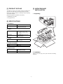
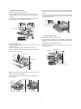
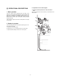
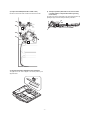
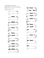
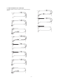
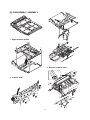
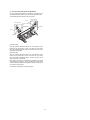
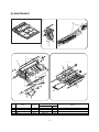
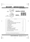
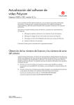
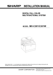
SERVICE MANUAL
CODE: 00ZARDU1//A1E
DIGITAL COPIER OPTION
DUPLEX MODULE
MODEL
AR-DU1
CONTENTS
[ 1 ] PRODUCT OUTLINE . . . . . . . . . . . . . . . . . . . . . . . . . . . . . . . . . . . 1
[ 2 ] SPECIFICATIONS . . . . . . . . . . . . . . . . . . . . . . . . . . . . . . . . . . . . . 1
[ 3 ] UNPACKING AND INSTALLATION . . . . . . . . . . . . . . . . . . . . . . . . 1
[ 4 ] EXTERNAL VIEW AND INTERNAL STRUCTURE . . . . . . . . . . . . 5
[ 5 ] OPERATIONAL DESCRIPTIONS . . . . . . . . . . . . . . . . . . . . . . . . . 6
[ 6 ] DISASSEMBLY, ASSEMBLY . . . . . . . . . . . . . . . . . . . . . . . . . . . . 10
[ 7 ] ADJUSTMENTS . . . . . . . . . . . . . . . . . . . . . . . . . . . . . . . . . . . . . . 11
[ 8 ] MAINTENANCE . . . . . . . . . . . . . . . . . . . . . . . . . . . . . . . . . . . . . . 13
[ 9 ] CIRCUIT DIAGRAM . . . . . . . . . . . . . . . . . . . . . . . . . . . . . . . . . . . 14
PARTS GUIDE
Parts marked with "!" is important for maintaining the safety of the set. Be sure to replace these parts with specified
ones for maintaining the safety and performance of the set.
SHARP CORPORATION
This document has been published to be used
for after sales service only.
The contents are subject to change without notice.
[1] PRODUCT OUTLINE
[3] UNPACKING AND
INSTALLATION
The model is an option for auto duplex copiers and installed to the
upper side of the paper feed port of the upper stage of the copier.
Note that the following equipment is separately required depending
on the copier conditions.
1. Unpacking
(Necessary equipment for installation of the AR-DU1)
* 16MB Memory (ICU PWB)
* 2-tray paper exit unit
3
[2] SPECIFICATIONS
(1) Installation
Installed by
Serviceman
Installing position
Upper side of the paper feed port of
the upper side of the copier
3
(2) Paper
Size
Paper weight
A3, B4, A4, A4R, B5, B5R, A5
(11" × 17"/8.5" × 14"/11" × 8.5"/
11" × 8.5R/8.5" × 5.5"/8.5" × 13"/
7.25" × 10.5")
2
4
5
56 ∼ 105g/* (Similar to the copier
paper feed section)
3
(3) Power
Power source
Supplied from the copier
(DC +5V, +24V)
6
(4) Power consumption
Max. power consumption
About 25W
Standby
About 0.2W
7
(5) External view
External dimensions
515(W) × 400 (D) × 120(H) mm
(Stored inside the copier)
Weight
About 5kg
2. Installation
Disconnect the power plug of the copier and follow the following
procedures.
–1–
Pull out the ADU unit inch by inch, and fit the ADU unit installing hole
on the front side with the screw hole of the rail, and fix with a fixing
screw.
1. Remove the paper exit unit.
Remove the paper exit unit from the copier.
Remove the stopper screws (2 pcs.) from the round hole of the rail.
•
Then, pull out the ADU unit and the rear side rail until it stops, and fix
the rear side rail to the ADU unit installing hole on the rear side with
the remaining fixing screw.
When installing the paper exit unit again, the stopper screw is not
required.
Then, remove the four fixing screws which are fixing the paper exit
unit to the copier rail, and remove the paper exit rail.
Fixing screw
Stopper screw
Stopper screw
Fixing screws
3. Install the paper exit unit.
★ Installation from the 1-tray paper exit unit
Fixing screws
Install the new 2-tray paper exit unit to the position of the paper exit
unit which was removed in procedure 1. Fix with the fixing screws (4
pcs.).
★ Installation from the 2-tray paper exit unit
2. Install the ADU unit.
Install the paper feed unit to the original position, and fix with the
fixing screws (4 pcs.).
Push the rails which are attached to the front and rear sides of the
copier into the copier.
Insert the ADu unit under the rail of the copier side (F, R sides).
Paper exit unit
At that time, insert the rear hook of the ADU unit just in front of the
rear side rail on the copier side.
Rear hook
Fixing screws
Rear side rail
Front side rail
Fixing screws (Short)
Slightly lift up the ADU unit and pass the rear side rail to the rear
hook, and pull out the rail until it stops.
Then pull out the front side rail until it stops and put the ADU unit on
the front side rail.
Rear side Front side
Rear hook
Rear side rail
Rear side rail
–2–
4. Remove the ADU unit harness cover and connect the
connector.
Rear side
Remove the fixing screw of the ADU unit, and remove the harness
cover.
0~0.5mm
Remove the connector of the connector storing section, and connect
it to the ADU unit connector.
Attach the pawl section of the removed harness cover to the ADU unit
and fix with a fixing screw.
At that time, treat the wires so that the connector is stored inside the
harness cover. Be careful not to pinch the wire with the harness
cover.
Insert the paper exit unit into the copier.
Harness cover
When the alignment guide is not shifted:
remove the paper from the ADU unit, press the CA key and cancel
the set mode.
Fixing screw
Connector
storing section
When the alignment guide is shifted:
1 Insert the paper exit unit.
2 Change the set value.
[EXECUTE] By this operation, the set value is
changed and alignment is
performed again.
Set value
<Example>
•
Connect the power plug of the copier to the power outlet, turn on the
power switch, and follow the following procedures.
Setting to 45
4
5. Change the system configuration setting.
5
[EXECUTE]
When the set value is changed by 1, the alignment guide width is
changed by 0.5 ∼ 0.6mm.
1 Perform the mode setting with the key operation of the copier.
★ Reference for changing the set value
P
C
2
6
0
1
40
(Shipment set value)
The guide is extended
The current set value is displayed with the above key operation.
(The value of 61 or greater or 39 or smaller is invalid.)
2 Change the set value to 2.
C
2
OK
3 Pull out the paper exit unit again.
With the above operation, the set value can
be changed.
4 Check that the clearance between the alignment guide and paper
is 0 ∼ 0.5mm.
The set value can be changed with the key operation.
At that time, be sure to shift the paper to the rear side of the
alignment guide for checking.
6. Check and adjust the alignment guide.
1 Set the adjustment mode of the alignment guide with the key
operation of the copier.
P
C
60
The guide is narrowed
5
2
0
Repeat procedures 1 through 4 repeatedly.
After adjustment, remove the paper from the ADU unit, press the
CA key and cancel the set mode.
1
7. Print off-center adjustment
1 Make a copy. If the center is shifted, set the adjustment mode of
the print off-center with the key operations of the copier.
With the above key operation, the set value is displayed. A sheet of
paper is fed from the paper feed section, and transported to the top of
the alignment plate of the ADU unit and stopped under the aligned
state.
P
C
5
0
1
0
2 Pull out the paper exit unit.
With the above key operation, the current set value is displayed.
3 Check that the clearance between the alignment guide and the
paper is 0 ∼ 0.5mm.
2 Select the item of ADU from the message menu with [ ↑ ] key and
[ ↓ ] key.
At that time, be sure to shift the paper to the rear side of the
alignment guide for checking.
Adjustment value: 1.7mm
–3–
3 Change the set value.
[EXECUTE] With the above operation,
the set value can be changed.
Set value
<Example>
•
When setting to one-digit value (5)
5
•
[EXECUTE]
When setting to two-digit value (15)
5
1
[EXECUTE]
When the value is changed by 1, the center position is shifted by
about 0.12mm.
★ Reference of set value change
0
(Shipment setting value)
The image is shifted to the front
of the paper.
99
The image is shifted to the rear
of the paper.
4 After adjustment, make a copy to check the center is not shifted.
If the center is shifted, repeat procedures 3 and 4 and check
again.
5 After adjustment, press the CA key to cancel the setting mode.
–4–
[4] EXTERNAL VIEW AND INTERNAL STRUCTURE
4
1. DPPD1
5
14
15
6. DTC1
12. DSCS
18. DAPD
7. DTC2
13
11. DSBS
17
3. DPPD3
8
2. DPPD2
9
16
10
No.
Code
Name
Type
Function and operation
1
DPPD1
Paper in detector 1
Photo transmission
ADU tray paper in detection
2
DPPD2
Paper in detector 2
Photo transmission
ADU tray paper in detection
3
DPPD3
Paper in detector 3
Photo transmission
ADU tray paper in detection
4
—
Reverse motor
Pulse motor
Paper reversion and transport drive
5
—
Alignment motor
Pulse motor
Paper alignment plate drive
6
DTC1
Transport clutch 1
7
DTC2
Transport clutch 2
Electromagnetic clutch
8
—
Transport roller 1
—
ADU tray paper transport
Electromagnetic clutch
9
—
Transport roller 2
—
ADU tray paper transport
10
—
Transport roller 3
—
ADU tray paper transport
11
DSBS
Paper exit/reverse gate solenoid
Solenoid
Selection of paper exit to the lower stage of the 2-tray
paper exit unit and the reverse route
12
DSCS
Contact/detach solenoid
Solenoid
Selection of paper storing and transport in ADU tray
13
—
Reverse roller
—
Selection of paper retaining and transport in paper
reversion
14
—
Transport roller
—
Paper transport
15
—
Alignment belt
—
Paper transport
16
—
Transport belt
—
Transport roller drive
—
Transport roller drive
Photo transmission
Alignment plate home position detection
17
—
Belt B
18
DAPD
Alignment plate home position detector
–5–
A. Operation for one sheet of paper
[5] OPERATIONAL DESCRIPTIONS
1) Reverse operation (Solenoid A = ON, solenoid B =
ON.)
1. Basic operation
Paper is transported down and held there by normal rotation of the
reverse roller C.
This unit is stored under the transport base of the copier. In the
duplex copy mode, the paper discharged from the fusing section after
single copy is reversed by the switchback operation made by combination of the solenoid in the 2-stage paper exit tray unit, the
solenoid and the reverse roller in the duplex module (hereinafter
referred to as ADU).
Then the paper is aligned by the ADU and transported to the copier
for duplex copy.
A
2. Details of operation
There are following three kinds of operations depending on the number and the size of papers.
A. Operation of one sheet of paper
B. Paper size A4 (11" × 8.5") Portrait or less, two or more copies
C. Paper size B5R Landscape or above, two or more copies
C
B
–6–
2) Paper exit to ADU (Solenoids A and B = OFF)
4) Transport operation (Solenoid D = ON, reverse motor
C normal rotation, Transport belt rotation by turning
on the clutch)
Reversion of the reverse roller C feeds the document to the ADU.
The paper in the ADU is transported to the copier transport section by
pressing the upper and lower transport rollers by solenoid D.
C
A
C
B
3) Alignment operation (Alignment motor operation)
The paper fed to the ADU is aligned to the center position by the
alignment motor.
(A)
–7–
D
ON
B. Paper size A4 (11" × 8.5") or less
(Example: Duplex copy of 12 sheets of single surface document)
2)
The basic operation is same as section A. The transport timing is
different.
5)
6)
4)
3)
6)
3)
(A) indicates the copier transport section.
(B) indicates the duplex unit.
(A)
1)
(B)
4)
1)
2)
5)
3)
4)
5)
2)
3)
6)
3)
1)
4)
6)
3)
5)
4)
5)
4)
1)
2)
6)
4)
2)
5)
1)
3)
1)
3)
2)
1)
2)
4)
3)
2)
5)
4)
3)
5)
4)
1)
6)
–8–
6)
6)
C. Paper size B5R or less, Landscape
The basic operation is same as section A. The transport timing is
different.
3)
1)
4)
3)
2)
4)
1)
1)
2)
1)
2)
1)
2)
2)
3)
4)
3)
4)
–9–
4)
[6] DISASSEMBLY, ASSEMBLY
2)
3)
2)
2)
2)
2)
1. Upper transfer section
1)
1)
7)
8)
1)
10)
8)
1)
7)
8)
7)
1)
2)
3)
4)
5)
6)
11)
2)
1)
2)
3)
4)
5)
6)
3. Reverse, transfer roller
2)
3)
5)
5)
1)
4)
1)
6)
2. Transfer roller
4)
1)
3)
1) 2)
4) 6)
3)
6)
3)
2)
1)
4)
2)
3)
2)
4)
1)
3)
3)
2)
1)
– 10 –
1)
1)
3)
7)
<Example>
[7] ADJUSTMENTS
•
When setting to 45
4
1. Adjustment item list
Item
SIM52-01
B. Print off-center adjustment
SIM50-10
[EXECUTE]
When the set value is changed by 1, the alignment guide width is
changed by 0.5 ∼ 0.6mm.
Adjustment procedure
A. Alignment guide check and adjustment
5
★ Reference of setting value change
40
(Shipment set value)
The guide is extended
C. Curl correction roller pressure
adjustment
60
The guide is narrowed
(The value of 61 or greater or 39 or smaller is invalid.)
3) Pull out the paper exit unit again.
2. Adjustments
4) Check that the clearance between the alignment guide and the
paper is 0 ∼ 0.5mm.
A. Alignment guide check and adjustment
At that time, be sure to shift the paper to the rear side of the
alignment guide. Repeat procedures 1) through 4) repeatedly for
checking.
1) Set the alignment guide adjustment mode with the key operation
of the copier.
P
C
5
2
0
After adjustment, remove the paper from the ADU unit, press the
CA key and cancel the setting mode.
1
With the above key operation, the set value is displayed. When
the EXECUTE key is pressed, a paper is fed from the selected
paper feed section and transported to the top of the alignment
plate and stopped under aligned state.
B. Print off-center adjustment
1) Make a copy. If the center is shifted, set to the adjustment mode
of the print off-center with the key operations of the copier.
2) Pull out the paper exit unit.
5
C
P
3) Check that the clearance between the alignment guide and the
paper is 0 ∼ 0.5mm.
0
1
0
Adjustment value: 1.7mm
At that time, shift the paper to the rear side of the alignment guide
for checking.
With the above key operation, the currently set value is displayed.
2) Select "ADU" item from the message menu with [ ↑ ] key and [ ↓ ]
key.
Rear side
3) Change the set value.
0~0.5mm
[EXECUTE] With the above operation,
the set value can be changed.
Set value
<Example>
•
Setting of one-digit value
5
When the alignment guide is not shifted:
•
Remove the paper from the ADU unit and press the CA key to cancel
the setting mode.
[EXECUTE]
Setting of two-digit value
5
1
[EXECUTE]
Then go to the next procedure (Print off-center adjustment).
When the set value is changed by 1, the print center is shifted by
about 0.125mm.
When the alignment guide is shifted:
1) Insert the paper exit unit.
★ Reference of changing the setting value
2) Change the set value.
0
[EXECUTE] By this operation, the set value is
changed and alignment is
performed again.
(Shipment setting value)
The image is shifted to the front
of the paper.
Set value
99
The image is shifted to the rear
of the paper.
4) After adjustment, make a copy again and check that the center is
not shifted.
If the center is still shifted, perform procedures 3) and 4) repeatedly for checking.
5) After completion of adjustment, press the CA key to cancel the
setting mode.
– 11 –
C. Curl correction roller pressure adjustment
The curl correction roller pressure is adjusted by changing the pressure adjustment plate position on the front and the rear frame sides.
The standard adjustment position is as shown below.
Rear frame side
Scale
Front frame side
Pressure adjustment
plate
Marking
Scale
Marking
(Front frame side)
Move the pressure adjustment plate in the arrow direction for the
marking on the duplex frame, and fix to the right end of the scale.
When the pressure adjustment plate is moved to the left of the scale,
the pressure is decreased.
(Rear frame side)
Move the pressure adjustment plate in the arrow direction for the
marking on the duplex frame, and fix to the left end of the scale.
When the pressure adjustment plate is moved to the right of the
scale, the pressure is decreased.
When paper curl correction is insufficient or exceeded in the duplex
mode resulting in a paper jam, change the attachment position of the
pressure adjustment plate from the standard position to change the
curl correction roller pressure.
An adjustment is required for some kinds of paper.
– 12 –
[8] MAINTENANCE
3
3
1
2
1
1
1
1
4
No.
Condition of execution
Name
Work item
1
Transport rollers
Cleaning
Maintenance service
80K
2
Transport paper guides
Cleaning
Maintenance service
80K
3
Gears
Lubrication
Maintenance service
80K
4
Belts
Check
Maintenance
240K
Timing of execution
– 13 –
Cycle
Remark
q
COPYRIGHT C 1998 BY SHARP CORPORATION
All rights reserved.
Printed in Japan.
No part of this publication may be reproduced,
stored in a retrieval system, or transmitted,
in any form or by any means,
electronic, mechanical, photocopying, recording, or otherwise,
without prior written permission of the publisher.
SHARP CORPORATION
Printing & Reprographic Systems Group
Quality & Reliability Control Center
Yamatokoriyama, Nara 639-1186, Japan
1998 May Printed in Japan S