1
ITW Dynatec
An Illinois Tool Works Company
31 Volunteer Drive
Hendersonville, TN 37075 USA
Telephone 615.824.3634
FAX 615.264.5222
OPERATIONS & SERVICE MANUAL #21-06
Revised 9/15/07
Adhesive Application Solutions • ISO 9001 Certified
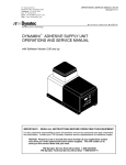
OPERATIONS AND SERVICE MANUAL
DYNADRUM 55 AIR-OPERATED
DRUM UNLOADER w. DynaControl V5.12MDU and up
DU553 Standard Model,
DU554 High Output Model &
PN 812045 Piston Pump Model
For an online copy of this manual, go to www.itwdynatec.com/manuals.htm
IMPORTANT ! - READ ALL INSTRUCTIONS BEFORE OPERATING THIS EQUIPMENT
It is the customer’s responsibility to have all operators and service personnel read and understand
this information. Contact your ITW Dynatec customer service representative for additional copies.
NOTICE! Please be sure to include the serial number of your application system
each time you order replacement parts and/or supplies. This will enable us to
send you the correct items that you need.
ITW Dynatec Service Parts Direct Dial: 1-800-538-9540
ITW Dynatec Technical Service Direct Dial: 1-800-654-6711
Moving Forward Through Technology™
Page ii
Revised 10/00
ITW Dynatec
An Illinois Tool Works Company
Adhesive Application Solutions
c. 2000
DYNADRUM 55 UNLOADER Manual #21-06
ITW Dynatec c. 2000
DYNADRUM 55 UNLOADER Manual #21-06
Page iii
Revised 2/07
TABLE OF CONTENTS
Chapter 1 Safety Precautions
Chapter - Page #
Electrical . . . . . . . . . . . . . . . . . . . . . . . . . . . . . . . . . . . . . . . . . . . . . . . . . . . . . . . . . . . . . . . . . . . . . . . . .
High Temperatures . . . . . . . . . . . . . . . . . . . . . . . . . . . . . . . . . . . . . . . . . . . . . . . . . . . . . . . . . . . . . . . . . .
High Pressure . . . . . . . . . . . . . . . . . . . . . . . . . . . . . . . . . . . . . . . . . . . . . . . . . . . . . . . . . . . . . . . . . . . . . .
Protective Covers . . . . . . . . . . . . . . . . . . . . . . . . . . . . . . . . . . . . . . . . . . . . . . . . . . . . . . . . . . . . . . . . . . .
Eye Protection & Protective Clothing . . . . . . . . . . . . . . . . . . . . . . . . . . . . . . . . . . . . . . . . . . . . . . . . . . .
Safe Installation and Operation . . . . . . . . . . . . . . . . . . . . . . . . . . . . . . . . . . . . . . . . . . . . . . . . . . . . . . . .
Treatment for Burns From Hot Melt Adhesives . . . . . . . . . . . . . . . . . . . . . . . . . . . . . . . . . . . . . . . . . . .
Service . . . . . . . . . . . . . . . . . . . . . . . . . . . . . . . . . . . . . . . . . . . . . . . . . . . . . . . . . . . . . . . . . . . . . . . . . . .
Explosion/ Fire Hazard . . . . . . . . . . . . . . . . . . . . . . . . . . . . . . . . . . . . . . . . . . . . . . . . . . . . . . . . . . . . . .
Lockout/ Tagout . . . . . . . . . . . . . . . . . . . . . . . . . . . . . . . . . . . . . . . . . . . . . . . . . . . . . . . . . . . . . . . . . . . .
Use of PUR Adhesives . . . . . . . . . . . . . . . . . . . . . . . . . . . . . . . . . . . . . . . . . . . . . . . . . . . . . . . . . . . . . .
1-1
1-1
1-1
1-2
1-2
1-2
1-2
1-3
1-3
1-3
1-3
Chapter 2 Description & Specifications
Description . . . . . . . . . . . . . . . . . . . . . . . . . . . . . . . . . . . . . . . . . . . . . . . . . . . . . . . . . . . . . . . . . . . . . . . .
Components Diagram . . . . . . . . . . . . . . . . . . . . . . . . . . . . . . . . . . . . . . . . . . . . . . . . . . . . . . . . . . . . . . .
Specifications . . . . . . . . . . . . . . . . . . . . . . . . . . . . . . . . . . . . . . . . . . . . . . . . . . . . . . . . . . . . . . . . . . . . . .
Dimensions . . . . . . . . . . . . . . . . . . . . . . . . . . . . . . . . . . . . . . . . . . . . . . . . . . . . . . . . . . . . . . . . . . . . . . .
2-1
2-1
2-2
2-4
Chapter 3 Installation & Start Up
Shipping & Handling Information . . . . . . . . . . . . . . . . . . . . . . . . . . . . . . . . . . . . . . . . . . . . . . . . . . . . . .
Service Requirements . . . . . . . . . . . . . . . . . . . . . . . . . . . . . . . . . . . . . . . . . . . . . . . . . . . . . . . . . . . . . . .
Installation . . . . . . . . . . . . . . . . . . . . . . . . . . . . . . . . . . . . . . . . . . . . . . . . . . . . . . . . . . . . . . . . . . . . . . . .
Electrical Controls . . . . . . . . . . . . . . . . . . . . . . . . . . . . . . . . . . . . . . . . . . . . . . . . . . . . . . . . . . . . . . . . . .
Pneumatic Controls . . . . . . . . . . . . . . . . . . . . . . . . . . . . . . . . . . . . . . . . . . . . . . . . . . . . . . . . . . . . . . . . .
Startup Procedure . . . . . . . . . . . . . . . . . . . . . . . . . . . . . . . . . . . . . . . . . . . . . . . . . . . . . . . . . . . . . . . . . . .
Drum Unloading . . . . . . . . . . . . . . . . . . . . . . . . . . . . . . . . . . . . . . . . . . . . . . . . . . . . . . . . . . . . . . . . . . .
Operator Adjustments . . . . . . . . . . . . . . . . . . . . . . . . . . . . . . . . . . . . . . . . . . . . . . . . . . . . . . . . . . . . . . .
3-1
3-1
3-1
3-2
3-2
3-3
3-5
3-6
Chapter 4 DynaControl Controller Set-Up
Temperature Control Functions in General . . . . . . . . . . . . . . . . . . . . . . . . . . . . . . . . . . . . . . . . . . . . . . .
Defining DynaControl Temperature Control Terms . . . . . . . . . . . . . . . . . . . . . . . . . . . . . . . . . . . . . . . .
Error Indication and Alarms . . . . . . . . . . . . . . . . . . . . . . . . . . . . . . . . . . . . . . . . . . . . . . . . . . . . . . . . . .
System Status Lights . . . . . . . . . . . . . . . . . . . . . . . . . . . . . . . . . . . . . . . . . . . . . . . . . . . . . . . . . . . . . . . .
Settings for a Typical Operation . . . . . . . . . . . . . . . . . . . . . . . . . . . . . . . . . . . . . . . . . . . . . . . . . . . . . . .
System Values that are Factory Programmed (not customer accessible) . . . . . . . . . . . . . . . . . . . . . . . .
Customer Programmable Values Preset at the Factory . . . . . . . . . . . . . . . . . . . . . . . . . . . . . . . . . . . . . .
Default Settings of the DynaControl Controller . . . . . . . . . . . . . . . . . . . . . . . . . . . . . . . . . . . . . . . . . . .
Helpful Tips for the User . . . . . . . . . . . . . . . . . . . . . . . . . . . . . . . . . . . . . . . . . . . . . . . . . . . . . . . . . . . . .
Serial Protocol . . . . . . . . . . . . . . . . . . . . . . . . . . . . . . . . . . . . . . . . . . . . . . . . . . . . . . . . . . . . . . . . . . . . .
4-1
4-1
4-4
4-6
4-6
4-7
4-7
4-8
4-9
4-10
Chapter 5 Programming of DynaControl Controller
Controller Safety Consideration . . . . . . . . . . . . . . . . . . . . . . . . . . . . . . . . . . . . . . . . . . . . . . . . . . . . . . .
Software Version . . . . . . . . . . . . . . . . . . . . . . . . . . . . . . . . . . . . . . . . . . . . . . . . . . . . . . . . . . . . . . . . . . .
Display & Keypad Reference . . . . . . . . . . . . . . . . . . . . . . . . . . . . . . . . . . . . . . . . . . . . . . . . . . . . . . . . .
Basic Programming Sequence: Quick Reference . . . . . . . . . . . . . . . . . . . . . . . . . . . . . . . . . . . . . . . . . .
Controller Setup . . . . . . . . . . . . . . . . . . . . . . . . . . . . . . . . . . . . . . . . . . . . . . . . . . . . . . . . . . . . . . . . . . . .
Turning the Controller On . . . . . . . . . . . . . . . . . . . . . . . . . . . . . . . . . . . . . . . . . . . . . . . . . . . . .
Language Selection . . . . . . . . . . . . . . . . . . . . . . . . . . . . . . . . . . . . . . . . . . . . . . . . . . . . . . . . . .
Temperature Scale Selection . . . . . . . . . . . . . . . . . . . . . . . . . . . . . . . . . . . . . . . . . . . . . . . . . . .
5-1
5-1
5-2
5-4
5-5
5-5
5-5
5-5
Page iv
Revised 8/06
ITW Dynatec c. 2000
DYNADRUM 55 UNLOADER Manual #21-06
Actual Temperatures Screen . . . . . . . . . . . . . . . . . . . . . . . . . . . . . . . . . . . . . . . . . . . . . . . . . . . . . . . . . .
Use of the Actual Temperatures Screen . . . . . . . . . . . . . . . . . . . . . . . . . . . . . . . . . . . . . . . . . . . . . . . . .
Programming Sequence . . . . . . . . . . . . . . . . . . . . . . . . . . . . . . . . . . . . . . . . . . . . . . . . . . . . . . .
Monitoring . . . . . . . . . . . . . . . . . . . . . . . . . . . . . . . . . . . . . . . . . . . . . . . . . . . . . . . . . . . . . . . . .
Setpoints Programming Screen . . . . . . . . . . . . . . . . . . . . . . . . . . . . . . . . . . . . . . . . . . . . . . . . . . . . . . . .
Use of the Setpoints Programming Screen . . . . . . . . . . . . . . . . . . . . . . . . . . . . . . . . . . . . . . . . . . . . . . .
Programming . . . . . . . . . . . . . . . . . . . . . . . . . . . . . . . . . . . . . . . . . . . . . . . . . . . . . . . . . . . . . . .
Monitoring . . . . . . . . . . . . . . . . . . . . . . . . . . . . . . . . . . . . . . . . . . . . . . . . . . . . . . . . . . . . . . . . .
Motor Programming Screen . . . . . . . . . . . . . . . . . . . . . . . . . . . . . . . . . . . . . . . . . . . . . . . . . . . . . . . . . .
Use of the Motor Programming Screen . . . . . . . . . . . . . . . . . . . . . . . . . . . . . . . . . . . . . . . . . . . . . . . . . .
Programming . . . . . . . . . . . . . . . . . . . . . . . . . . . . . . . . . . . . . . . . . . . . . . . . . . . . . . . . . . . . . . .
Monitoring . . . . . . . . . . . . . . . . . . . . . . . . . . . . . . . . . . . . . . . . . . . . . . . . . . . . . . . . . . . . . . . . .
Service Functions Screens . . . . . . . . . . . . . . . . . . . . . . . . . . . . . . . . . . . . . . . . . . . . . . . . . . . . . . . . . . . .
Service Functions Screen 1/3 . . . . . . . . . . . . . . . . . . . . . . . . . . . . . . . . . . . . . . . . . . . . . . . . . . . . . . . . .
High/ Low Temperature Deviation . . . . . . . . . . . . . . . . . . . . . . . . . . . . . . . . . . . . . . . . . . . . . .
Standby Temperature . . . . . . . . . . . . . . . . . . . . . . . . . . . . . . . . . . . . . . . . . . . . . . . . . . . . . . . . .
Standby Time Delay . . . . . . . . . . . . . . . . . . . . . . . . . . . . . . . . . . . . . . . . . . . . . . . . . . . . . . . . .
Setpoint Limitation . . . . . . . . . . . . . . . . . . . . . . . . . . . . . . . . . . . . . . . . . . . . . . . . . . . . . . . . . .
Temperature Offset . . . . . . . . . . . . . . . . . . . . . . . . . . . . . . . . . . . . . . . . . . . . . . . . . . . . . . . . . .
Sequential Heating . . . . . . . . . . . . . . . . . . . . . . . . . . . . . . . . . . . . . . . . . . . . . . . . . . . . . . . . . .
Temperature Scale . . . . . . . . . . . . . . . . . . . . . . . . . . . . . . . . . . . . . . . . . . . . . . . . . . . . . . . . . . .
Change Security Lock . . . . . . . . . . . . . . . . . . . . . . . . . . . . . . . . . . . . . . . . . . . . . . . . . . . . . . . .
Service Functions Screen 2/3 . . . . . . . . . . . . . . . . . . . . . . . . . . . . . . . . . . . . . . . . . . . . . . . . . . . . . . . . .
Customer Zone Names . . . . . . . . . . . . . . . . . . . . . . . . . . . . . . . . . . . . . . . . . . . . . . . . . . . . . . .
Power On Configuration . . . . . . . . . . . . . . . . . . . . . . . . . . . . . . . . . . . . . . . . . . . . . . . . . . . . . .
Factory Defaults . . . . . . . . . . . . . . . . . . . . . . . . . . . . . . . . . . . . . . . . . . . . . . . . . . . . . . . . . . . .
Keypad Locking . . . . . . . . . . . . . . . . . . . . . . . . . . . . . . . . . . . . . . . . . . . . . . . . . . . . . . . . . . . .
PC Link . . . . . . . . . . . . . . . . . . . . . . . . . . . . . . . . . . . . . . . . . . . . . . . . . . . . . . . . . . . . . . . . . . .
Language . . . . . . . . . . . . . . . . . . . . . . . . . . . . . . . . . . . . . . . . . . . . . . . . . . . . . . . . . . . . . . . . . .
LCD Contrast . . . . . . . . . . . . . . . . . . . . . . . . . . . . . . . . . . . . . . . . . . . . . . . . . . . . . . . . . . . . . . .
System Logbook . . . . . . . . . . . . . . . . . . . . . . . . . . . . . . . . . . . . . . . . . . . . . . . . . . . . . . . . . . . .
Change Security Lock . . . . . . . . . . . . . . . . . . . . . . . . . . . . . . . . . . . . . . . . . . . . . . . . . . . . . . . .
Service Functions Screen 3/3 . . . . . . . . . . . . . . . . . . . . . . . . . . . . . . . . . . . . . . . . . . . . . . . . . . . . . . . . .
Programming at Main Scheduler Screen . . . . . . . . . . . . . . . . . . . . . . . . . . . . . . . . . . . . . . . . . . . . . . . . .
Use of the Main Scheduler Screen . . . . . . . . . . . . . . . . . . . . . . . . . . . . . . . . . . . . . . . . . . . . . . . . . . . . .
Programming of 7-Day Scheduler . . . . . . . . . . . . . . . . . . . . . . . . . . . . . . . . . . . . . . . . . . . . . . . . . . . . . .
Use of the 7-Day Scheduler Screen . . . . . . . . . . . . . . . . . . . . . . . . . . . . . . . . . . . . . . . . . . . . . . . . . . . . .
Programming . . . . . . . . . . . . . . . . . . . . . . . . . . . . . . . . . . . . . . . . . . . . . . . . . . . . . . . . . . . . . . .
5-6
5-6
5-7
5-7
5-8
5-9
5-9
5-9
5-10
5-11
5-11
5-11
5-12
5-12
5-13
5-13
5-13
5-13
5-13
5-14
5-14
5-14
5-15
5-15
5-15
5-16
5-16
5-16
5-16
5-16
5-16
5-16
5-17
5-18
5-19
5-20
5-21
5-21
Chapter 6 Maintenance
Inspection & Checks . . . . . . . . . . . . . . . . . . . . . . . . . . . . . . . . . . . . . . . . . . . . . . . . . . . . . . . . . . . . . . . .
Fasteners . . . . . . . . . . . . . . . . . . . . . . . . . . . . . . . . . . . . . . . . . . . . . . . . . . . . . . . . . . . . . . . . . . . . . . . . .
Hose Fittings . . . . . . . . . . . . . . . . . . . . . . . . . . . . . . . . . . . . . . . . . . . . . . . . . . . . . . . . . . . . . . . . . . . . . .
Motor . . . . . . . . . . . . . . . . . . . . . . . . . . . . . . . . . . . . . . . . . . . . . . . . . . . . . . . . . . . . . . . . . . . . . . . . . . . .
6-1
6-1
6-1
6-1
Chapter 7 Troubleshooting
Part 1: Unloader Troubleshooting & Service . . . . . . . . . . . . . . . . . . . . . . . . . . . . . . . . . . . . . . . . . . . . .
General Troubleshooting Notes . . . . . . . . . . . . . . . . . . . . . . . . . . . . . . . . . . . . . . . . . . . . . . . . . . . . . . . .
Unloader Mechanical Troubleshooting Guide for Gear Pump Models . . . . . . . . . . . . . . . . . . . . . . . . .
Unloader Mechanical Troubleshooting Guide for Piston Pump Models . . . . . . . . . . . . . . . . . . . . . . . .
Unloader Electrical Troubleshooting Guide . . . . . . . . . . . . . . . . . . . . . . . . . . . . . . . . . . . . . . . . . . . . . .
Heaters . . . . . . . . . . . . . . . . . . . . . . . . . . . . . . . . . . . . . . . . . . . . . . . . . . . . . . . . . . . . . . . . . . . . . . . . . . .
Heaters, Sensors and Switches on Optional Piston Pump Models . . . . . . . . . . . . . . . . . . . . . . . . . . . . .
7-1
7-1
7-1
7-2
7-3
7-3
7-3
ITW Dynatec c. 2000
DYNADRUM 55 UNLOADER Manual #21-06
Page v
Revised 2/07
Part 2: DynaControl Controller Troubleshooting . . . . . . . . . . . . . . . . . . . . . . . . . . . . . . . . . . . . . . . . . . 7-4
General Troubleshooting Notes . . . . . . . . . . . . . . . . . . . . . . . . . . . . . . . . . . . . . . . . . . . . . . . . . . . . . . . .
Preliminary Checks . . . . . . . . . . . . . . . . . . . . . . . . . . . . . . . . . . . . . . . . . . . . . . . . . . . . . . . . . . . . . . . . .
Error Messages . . . . . . . . . . . . . . . . . . . . . . . . . . . . . . . . . . . . . . . . . . . . . . . . . . . . . . . . . . . . . . . . . . . .
Hose/ Valve Heater Troubleshooting Tip . . . . . . . . . . . . . . . . . . . . . . . . . . . . . . . . . . . . . . . . . . . . . . . .
Motor Speed Control PC Board Re-set . . . . . . . . . . . . . . . . . . . . . . . . . . . . . . . . . . . . . . . . . . . . . . . . . .
High-Temperature Redundant Overtemp Thermostat . . . . . . . . . . . . . . . . . . . . . . . . . . . . . . . . . . . . . . .
Lithium Battery on PC Boards . . . . . . . . . . . . . . . . . . . . . . . . . . . . . . . . . . . . . . . . . . . . . . . . . . . . . . . .
Handling Printed Circuit Boards . . . . . . . . . . . . . . . . . . . . . . . . . . . . . . . . . . . . . . . . . . . . . . . . . . . . . . .
CPU Printed Circuit Board & Layout Illustration . . . . . . . . . . . . . . . . . . . . . . . . . . . . . . . . . . . . . . . . . .
Display CPU Printed Circuit Board & Layout Illustration . . . . . . . . . . . . . . . . . . . . . . . . . . . . . . . . . . .
Motor Control Interface Printed Circuit Board & Layout Illustration . . . . . . . . . . . . . . . . . . . . . . . . . .
Motor Speed Control Printed Circuit Board & Layout Illustration . . . . . . . . . . . . . . . . . . . . . . . . . . . .
Optional Signal Isolator Printed Circuit Board . . . . . . . . . . . . . . . . . . . . . . . . . . . . . . . . . . . . . . . . . . . .
48-Zone Power Printed Circuit Board & Layout Illustration . . . . . . . . . . . . . . . . . . . . . . . . . . . . . . . . .
7-4
7-4
7-4
7-4
7-4
7-5
7-5
7-6
7-7
7-8
7-9
7-10
7-11
7-12
Chapter 8 Disassembly & Re-assembly Procedures
General Notes . . . . . . . . . . . . . . . . . . . . . . . . . . . . . . . . . . . . . . . . . . . . . . . . . . . . . . . . . . . . . . . . . . . . .
Pump Assembly Replacement . . . . . . . . . . . . . . . . . . . . . . . . . . . . . . . . . . . . . . . . . . . . . . . . . . . . . . . . .
Platen Replacement . . . . . . . . . . . . . . . . . . . . . . . . . . . . . . . . . . . . . . . . . . . . . . . . . . . . . . . . . . . . . . . . .
Platen Reassembly . . . . . . . . . . . . . . . . . . . . . . . . . . . . . . . . . . . . . . . . . . . . . . . . . . . . . . . . . . . . . . . . . .
Wiper Seal Replacement . . . . . . . . . . . . . . . . . . . . . . . . . . . . . . . . . . . . . . . . . . . . . . . . . . . . . . . . . . . . .
Electrical Parts Replacement . . . . . . . . . . . . . . . . . . . . . . . . . . . . . . . . . . . . . . . . . . . . . . . . . . . . . . . . . .
Thermostats . . . . . . . . . . . . . . . . . . . . . . . . . . . . . . . . . . . . . . . . . . . . . . . . . . . . . . . . . . . . . . . . . . . . . . .
Heaters . . . . . . . . . . . . . . . . . . . . . . . . . . . . . . . . . . . . . . . . . . . . . . . . . . . . . . . . . . . . . . . . . . . . . . . . . . .
RTD Sensors . . . . . . . . . . . . . . . . . . . . . . . . . . . . . . . . . . . . . . . . . . . . . . . . . . . . . . . . . . . . . . . . . . . . . .
8-1
8-1
8-2
8-2
8-3
8-4
8-4
8-4
8-5
Chapter 9 Recommended Spare Parts List & Options
Recommended Spare Parts List . . . . . . . . . . . . . . . . . . . . . . . . . . . . . . . . . . . . . . . . . . . . . . . . . . . . . . . . 9-1
Options . . . . . . . . . . . . . . . . . . . . . . . . . . . . . . . . . . . . . . . . . . . . . . . . . . . . . . . . . . . . . . . . . . . . . . . . . . . 9-2
Chapter 10 Component Illustrations & Bills of Material
DynaDrum Unloader w. Gear Pump: Bill Of Materials and Exploded Views . . . . . . . . . . . . . . . . . . . .
DynaDrum Unloader w. 15:1 Piston Pump: Bill Of Materials and Exploded Views . . . . . . . . . . . . . . .
Air Control Box: Bill of Materials & Exploded View . . . . . . . . . . . . . . . . . . . . . . . . . . . . . . . . . . . . . .
Optional ASU Fill Kit: Bill of Materials & Exploded View . . . . . . . . . . . . . . . . . . . . . . . . . . . . . . . . . .
Lid Assembly: Bill of Materials & Exploded View . . . . . . . . . . . . . . . . . . . . . . . . . . . . . . . . . . . . . . . .
10-2
10-6
10-8
10-10
10-12
Chapter 11 Engineering Drawings
Pneumatic Schematic . . . . . . . . . . . . . . . . . . . . . . . . . . . . . . . . . . . . . . . . . . . . . . . . . . . . . . . . . . . . . . . . 11-2
Optional Fill Kit Schematic . . . . . . . . . . . . . . . . . . . . . . . . . . . . . . . . . . . . . . . . . . . . . . . . . . . . . . . . . . . 11-3
Electrical Schematics
Panel Box Layout
Appendix
Gear Pump Manual
Piston Pump (15:1) Manual
Hood Vent
Page vi
Revised 8/06
ITW Dynatec
An Illinois Tool Works Company
ITW Dynatec c. 2000
DYNADRUM 55 UNLOADER Manual #21-06
Page 1-1
Revised 1/07
ITW Dynatec c. 1997
ALL MODELS
Chapter 1
SAFETY PRECAUTIONS
All operators and service personnel must read
and understand this manual before operating
or servicing equipment.
All maintenance and service on this equipment must be performed by trained technicians.
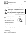
Electrical
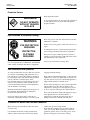
DANGER
HIGH VOLTAGE
Dangerous voltages exist at several points in this
equipment. To avoid personal injury, do not touch
exposed connections and components while input
power is on. Disconnect, lockout and tag external
electrical power before removing protective panels.
A secure connection to a reliable earth ground is
essential for safe operation.
A disconnect switch with lockout capability must be
provided in the line ahead of the unit. Wiring used to
supply electrical power should be installed by a
qualified electrician.
High Temperatures
WARNING
HOT
SURFACE
Severe burns can occur if unprotected skin comes in
contact with molten adhesive or hot application system
parts.
Safety glasses, gloves and long- sleeved clothing must
be worn whenever working with or around adhesive
application systems.
High Pressure
WARNING
HIGH PRESSURE
PRESENT
To avoid personal injury, do not operate the equipment
without all covers, panels and safety guards properly
installed.
To prevent serious injury from molten adhesive under
pressure when servicing the equipment, disengage the
pumps and relieve the adhesive system’s hydraulic
pressure (e.g., trigger the heads, hand-held applicators,
and/or other application devices into a waste container)
before opening any hydraulic fittings or connections.
IMPORTANT NOTE: Even when a system’s pressure
gauge reads “0” psig, residual pressure and trapped air
can remain within it causing hot adhesive and pressure
to escape without warning when a filter cap or a hose
or hydraulic connection is loosened or removed. For
this reason, always wear eye protection and protective
clothing.
Either of the two High Pressure symbols shown may be
used on equipment.
Page 1-2
Revised 3/97
ITW Dynatec c. 1997
ALL MODELS
Protective Covers
WARNING
DO NOT OPERATE
WITHOUT GUARDS
IN PLACE
Keep all guards in place!
To avoid personal injury, do not operate the application
system without all covers, panels and safety guards
properly installed.
Eye Protection & Protective Clothing
WARNING
EYE PROTECTION
REQUIRED
PROTECTIVE
CLOTHING
REQUIRED
It is very important that you PROTECT YOUR EYES
when working around hot melt adhesive equipment!
Wear safety glasses with side shields which conform to
ANSI Z87.1 or EN166.
Failure to wear safety glasses could result in severe eye
injury.
It is important to protect yourself from potential burns
when working around hot melt adhesive equipment.
Wear protective gloves and long-sleeved, protective
clothing to prevent burns that could result from contact
with hot material or hot components.
Always wear steel-reinforced safety shoes.
Safe Installation and Operation
To avoid possible failure of hoses, make sure all hoses
are routed to avoid kinking, tight radius turns (8” or
less) and abrasive contact. Hot-melt hoses should not
have prolonged contact with heat-absorbing surfaces
such as cold floors or metal troughs. These
heat-absorbing surfaces can alter adhesive flow and
cause incorrect calibration. Hoses should never be
covered with materials that prevent heat dissipation,
such as insulation or sheathing.
Read this manual before applying electrical power to
the equipment. Equipment may be damaged by
incorrect electrical connections.
Do not use adhesive that is dirty or that may be
chemically contaminated. Doing so can cause system
clogging and pump damage.
When adhesive hand-held applicators or other movable
applicators are used, never point them at yourself or at
any other person. Never leave a hand-held applicator’s
trigger unlocked when not actually in use.
Do not operate the hopper or other system components
without adhesive for more than 15 minutes if the
temperature is 150 degrees C (300 degrees F) or more.
To do so will cause charring of the residual adhesive.
Never activate the heads, hand-held applicators and/ or
other application devices until the adhesive’s
temperature is within the operating range. Severe
damage could result to internal parts and seals.
Treatment for Burns From Hot Melt Adhesives
Burns caused by hot melt adhesive must be treated
at a burn center.
Care should be used when working with hot melt
adhesives in the molten state. Because they rapidly
solidify, they present a unique hazard.
Even when first solidified, they are still hot and can
cause severe burns. When working near a hot melt
application system, always wear safety gloves, safety
glasses and long-sleeved, protective clothing.
Page 1-3
Revised 1/07
ITW Dynatec c. 1997
ALL MODELS
Always have first-aid information and supplies
available.
Call a physician and/or an emergency medical
technician immediately.
Service
Refer all servicing to qualified personnel only.
Explosion/ Fire Hazard
Never operate this unit in an explosive environment.
Use cleaning compounds recommended by ITW
Dynatec or your adhesive supplier only. Flash points
of cleaning compounds vary according to their composition, so consult with your supplier to determine the
maximum heating temperatures and safety precautions.
Lockout/ Tagout
Follow OSHA 1910.147 (Lockout/ Tagout Regulation)
for equipment’s lockout procedures and other important lockout/ tagout guidelines.
Be familiar with all lockout sources on the equipment.
Even after the equipment has been locked out, there
may be stored energy in the application system, particularly in the capacitors within the panel box. To ensure
that all stored energy is relieved, wait at least one minute before servicing electrical capacitors.
Use of PUR (Polyurethane) Adhesives
PUR adhesives emit fumes (MDI and TDI) that can be
dangerous to anyone exposed to them. These fumes
cannot be detected by the sense of smell. ITW Dynatec
strongly recommends that an exhaust hood or system
be installed over any PUR system.
Consult with your adhesive manufacturer for specifics
about required ventilation.
CAUTION: Because of the nature of PUR
adhesives to strongly bond in the presence
of moisture, care must be taken to prevent
them from curing inside Dynatec equipment. If PUR
adhesive solidifies in a unit, the unit must be replaced.
Always purge old PUR adhesive from the system per
your adhesive manufacturer’s instructions and timetable. ALLOWING PUR ADHESIVE TO CURE IN A
UNIT VOIDS ITW DYNATEC’S WARRANTY.
In This Manual
WARNINGS and CAUTIONS are found throughout
this manual.
WARNINGS mean that failure to observe the specific
instructions may cause injury to personnel.
CAUTIONS mean that failure to observe the specific
instructions may damage the equipment.
Page 1-4
Revised 3/97
ITW Dynatec
An Illinois Tool Works Company
Adhesive Application Solutions
ITW Dynatec c. 1997
ALL MODELS
Page 2--1
Revised 4/01
ITW Dynatec c. 2000
DYNADRUM 55 UNLOADER Manual #21-06
Chapter 2
DESCRIPTION & SPECIFICATIONS
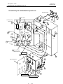
Description
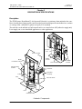
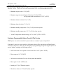
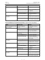
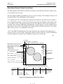
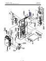
The ITW Dynatec DynaDrum 55 Air-Operated Unloader is a stationary drum unloader that combines a heated platen, pump and all controls needed to melt and dispense hot melt adhesives, sealants
or coatings from a standard 55-gallon steel pail (U.S. standard).
The unloader can be utilized as a bulk-transfer unit or as a stand-alone ASU (adhesive supply unit).
It can supply one or two hand-held applicators or other applicators.
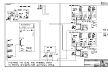
Junction
Box
Ram Assembly
Platen
Sensor
Motor
Pnuematic Controls
Pressure Relief
Alternate Hose
Position
Controller
Panel Box
Assembly
Pump
Vent
Pressure Relief
Hose
Platen
(Follower Plate)
Unloader Components
Pnuematic
Controls
Page 2--2
Revised 3/06
ITW Dynatec c. 2000
DYNADRUM 55 UNLOADER Manual #21-06
Specifications
Environmental:
Storage/ shipping temperature . . . . . . . . . . . . . . . . . . . . . . . . . . . . -40°C to 70°C (-40°F to 158°F)
Ambient service temperature . . . . . . . . . . . . . . . . . . . . . . . . . . . . . . . -7°C to 50°C (20°F to 122°F)
Physical:
Dimensions . . . . . . . . . . . . . . . . . . . . . . . . . . . . . . . . . see dimensional layouts on following page
Weight . . . . . . . . . . . . . . . . . . . . . . . . . . . . . . . . . . . . . . . . . . . . . . . . . . . . . . . . . . . . . . . . . 1600 lb.
Drum size . . . . . . . . . . . . . . . . . . . . . . . . . . . . . . . . . . . . . . . . . standard U.S. 55 gallon (208 liters)
Drum diameter . . . . . . . . . . . . . . . . . . . . . . . . . . . . . . . . . . . . . . . . . . . . . . . . 22.5 inches (570mm)
Gear pump: Model 553 (standard) . . . . . . . . . . . . . . . . . . . . . . . . . . . . 30cc, positive displacement
Gear pump: Model 554 (high output) . . . . . . . . . . . . . . . . . . . . . . . . . 45cc, positive displacement
Piston pump/ air motor ratio (optional) . . . . . . . . . . . . . . . . . . . . . . . . . . . . . . . . . . . . . . . . . . . 15:1
Motor . . . . . . . . . . . . . . . . . . . . . . . . . . . . . . . . . . . . . . . . . . . . 1 HP, variable speed, AC, brushless
Controller . . . . . . . . . . . . . . . . . . . modular, fluorescent digital display with keypad, DynaControl
Hose . . . . . . . . . . . . . . . . . . . . . . . . . . . . . . . . . . . . . . . . . . . . . . . . . . 24 foot x 0.625” ID Dynaflex
Performance:
Temperature range . . . . . . . . . . . . . . . . . . . . . . . . . . . . . . . . . . . . 38°C to 220°C (100°F to 425°F)
Warm-up time . . . . . . . . . . . . . . . . . . . . . . . . . . . . . . . . . . . . . . . . . . . . . . . . . . . . . . . . . 40 minutes
Adhesive delivery . . . . . . . . . . . . . . . . . . . . . . . . . . . . . . . . . . . . . . . . . Continuous or On-Demand
Adhesive viscosity* . . . . . . . . . . . . . . . 100 to 5,000,000 mPa. sec. (100 to 5,000,000 centipoise)
* Flow rates of various materials are dependent on their physical characteristics
Adhesive pressure range . . . . . . . . . . . . . . . . . . . . . . . . . . 69 bar maximum (1000 psi maximum)
Maximum output rate: Model 553 (standard) . . . . . . . . . . . . . . . . . . . . . . . . . . . . . . . . . 300 lb./hr*
Maximum output rate: Model 554 (high output) . . . . . . . . . . . . . . . . . . . . . . . . . . . . . . 400 lb./hr.*
Noise emission . . . . . . . . . . . . . . . . . . . . . . . . . . . . . . . . . . . . . . . . . . . . . . . . . . . . . . . . . tbd dB(A)
Drum change time . . . . . . . . . . . . . . . . . . . . . . . . . . . . . . . . . . . . . . . . . . . . . . . . . . . . . . . 5 minutes
Air Requirements:
Operating air pressure range . . . . . . . . . . . . . . . . . . . . . . . . . . . . . . . . 4.1 to 5.5 bar (60 to 80 psi)
Electrical:
Supply voltage . . . . . . . . . . . . . . . . . . . . . . . . . . . . . . . . . . . . . . . . . . . 200-240 VAC/ 3p/ 50-60 Hz
. . . . . . . . . . . . . . . . . . . . . . . . . . . . . . . . . . . . . . . . . . . . . . . . . . . 380-400 VAC/ 3p/ 50-60 Hz
Power requirements (240v) . . . . . . . . . . . . . . . . . . . . . . . . . . . . . . . . . . . . . . . . . . . . . 100 amp, 3p
Power requirements (380v) . . . . . . . . . . . . . . . . . . . . . . . . . . . . . . . . . . . . . . . . . . . . . . 63 amp, 3p
Wattage, maximum:
Platen . . . . . . . . . . . . . . . . . . . . . . . . . . . . . . . . . . . . . . . . . . . . . . . . . . . . . . 27,500 watts max.
Transfer block . . . . . . . . . . . . . . . . . . . . . . . . . . . . . . . . . . . . . . . . . . . . . . . . . 1000 watts max.
Hand-held applicator . . . . . . . . . . . . . . . . . . . . . . . . . . . . . . . . . . . . . . . . . . . . 200 watts max.
Hose, applicator . . . . . . . . . . . . . . . . . . . . . . . . . . . . . . . . . . . . . . . . . . . . . . . 1000 watts max.
Hose, transfer . . . . . . . . . . . . . . . . . . . . . . . . . . . . . . . . . . . . . . . . . . . . . . . . . 2000 watts max.
* Based on a 4000 centipoise PSA hotmelt at 350°F
ITW Dynatec c. 2000
DYNADRUM 55 UNLOADER Manual #21-06
Page 2--3
Revised 7/06
Pressurized Air (Optional Piston Pump Models):
Maximum air pressure supply . . . . . . . . . . . . . . . . . . . . . . . . . . . . . . . . . . . . 8.22 bar (120 psig)
Maximum recommended pump speed . . . . . . . . . . . . . . . . . . . . . . . . . depends on adhesive used
Air consumption at 60 pump cycles per minute . . . . . . . . . . . . . . . . TBD normal liters/ minute
(TBD SCFM at 100 psig)
DynaControl Temperature Control:
Power board . . . . . . . . . . . . . . . . . . . . . . . . . . . . . . . . 48 zones per board, modular construction
Display type . . . . . . . . . . . . . . . . . . . . . . . . . . . . . . . . . . . . . . . . . . . . . . . . graphic, liquid crystal
Temperature control zones . . . . . . . . . . . . . . . . . . . . . . . . . . . . . . . . . . . . solid state relay output
Solid state relay input . . . . . . . . . . . . . . . . . . . . . . . . . . . . . . . . . . . . . . . . . . . . . . . . . 3-15 VDC
Line speed inputs . . . . . . . . . . . . . . . . . . . . . . . . . . . . . . . . . . . . . . . . . . . . . . . . . . . . . . . . . 1 to 2
Other:
Display languages . . . . . . . . . English, French, German, Spanish, Swedish, Italian, Portugese,
Japanese and Dutch
Operator interface . . . . . . . . . . . . . . . . . . . . . . . . . . . . . . multi-zone, liquid crystal display with
alpha/numeric keyboard and function keys
Temperature standby . . . . . . . . . . . . . . . . . . . . . . . . . . . . . . . . . . . . . . . . . . . . . . . . . . . . . . . . yes
High and low temp alarms . . . . . . . . . . . . . . . . . . . . . . . . . . . . . . . . . . . . . . . . . . . . . . . . . . . . yes
Ready interlock . . . . . . . . . . . . . . . . . . . . . . . . . . . . . . . . . . . . . . . . . . . . . . . . . . . . . . . . . . . . yes
Password protection . . . . . . . . . . . . . . . . . . . . . . . . . . . . . . . . . . . . . . . . . . . . . . . . . . . . . . . . . yes
Sequential heating . . . . . . . . . . . . . . . . . . . . . . . . . . . . . yes (hopper, hose, head staged heating)
Sensor open alarm . . . . . . . . . . . . . . . . . . . . . . . . . . . . . . . . . . . . . . . . . . . . . . . . . . . . . . . . . . yes
RS232 and RS485 communications capable . . . . . . . . . . . . . . . . . . . . . . . . . . . . . . . . . . . . . . yes
Line Speed Tracking . . . . . . . . . . . . . . . . . . . . . . . . . . . . . . . . . . . . . . . . . . . . . . . . . . . . . . . . yes
Seven-day scheduler . . . . . . . . . . . . . . . . . . . . . . . . . . . . . . . . . . . . . . . . . . . . . . . . . . . . . . . . yes
Page 2--4
Revised 7/02
ITW Dynatec c. 2000
DYNADRUM 55 UNLOADER Manual #21-06
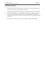
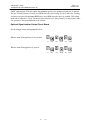
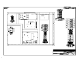
B
A
F
G
E
C
D
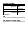
DIMENSION
mm
inches
A
B
C
D
E
2768
109.00
1727
68.00
736.6
29.00
1536.7 102
60.50 4.00
F
G
635
25.00
1219
48.00
DYNADRUM 55 Drum Unloader Installation Dimensions
Page 3--1
Revised 4/01
ITW Dynatec c. 2000
DYNADRUM 55 UNLOADER Manual #21-06
Chapter 3
INSTALLATION & OPERATION
Handling & Shipping Information
The Dynadrum unloader system is shipped in a wooden packing case attached to a wooden pallet
suitable for forklift handling. Enclosed are the melt unit, control panel box and individual boxes containing the other necessary components to assemble the system.
Service Requirements
The Dynadrum unloader is configured for either 240 volt/ 3 phase or 480 volt/ 3 phase power. Internal transformers, if required, provide 240v/ 3 phase voltage for hoses, applicators and controls.
Electrical power is connected to the upper disconnect circuit breaker terminals located in the control
panel box. A conduit opening must be customer-provided in the panel box for the power leads.
Air pressure is supplied through a 1/4” NPT fitting located at the air control panel. The air supply
line should be a minimum of 1/4”. Air pressure requirements are 60 to 80 psi.
Installation
The Dynadrum unloader has been tested at the factory and will be ready for operation after completing the following steps.
CAUTION: Prior to installation read the manual throughly. DO NOT operate the
unloader in an ambient temperature of less than 20°°F (-5°°C) or higher than 120°°F
(50°°C).
1. Position the unit so that it is convenient for drum loading and with easy access to the work
area. Provide adequate access to the control panel. Be certain there is a minimum of 9 feet
(2.95m) of overhead clearance.
2. Bolt unloader and panel box securely to the floor with 1/2” dia. x 3” bolts and flat washers.
WARNING
To prevent injury to personnel, the unloader and control panel box must be firmly
secured to the floor.
3. Connect air supply line (minimum size 1/4”) to the air control panel located on the left
cylinder of the unit.
4. Locate the master circuit breaker in the upper right corner of the controller’s panel box.
Refer to schematic in Chapter 11 for proper wiring connections.
DANGER HIGH VOLTAGE
To prevent serious or fatal injury, unit must be installed in accordance with applicable
codes and be properly grounded.
Page 3--2
Revised 4/01
ITW Dynatec c. 2000
DYNADRUM 55 UNLOADER Manual #21-06
5. Positively identify the line voltage and be certain that it matches the voltage on the electrical
data plate.
CAUTION: Incorrect voltage will cause severe damamge to the equipment
6. Connect the ground wire (green) to the ground bar in the lower right corner of the panel box.
Connect the other power leads to the circuit breaker line terminals as shown on the wiring
schematic.
7. Connect delivery hoses and applicator(s) if applicable. See their respective manuals for
installation instructions.
Electrical Controls
Description
Function
Indication
Circuit Breaker Switch
Master ON/ OFF &
circuit breaker
Switch down = System OFF
Switch up = System ON
DynaController
the controller is detailed in Chapters 4 & 5 of this manual
Pneumatic Controls
The controls on the pneumatic control box are:
Description
Function
Indication
3 knobs, regulators &
gauges
Controls and indicates
Up (left hand), Down (middle)
& Air Inject (right) air pressure
Right = Increases pressure
Left = Decreases pressure
Lever operator
Controls ram (platen) position
UP = Raises platen
DOWN = Lowers platen
Middle = Maintains position
Follower blow-off
button (red)
Injects air to open valve &
retract the platen
Push = Injects air
Knob, coalescing filter,
regulator & gauge (located
Factory set
on side of control box)
Removes water and air from
incoming air. Indicates shop air
pressure.
Vent Knob (located on
the platen)
Relieves trapped air
in drum
Screw In = Closed
Screw Out = Open
Page 3--3
Revised 4/01
ITW Dynatec c. 2000
DYNADRUM 55 UNLOADER Manual #21-06
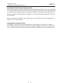
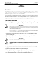
FOLLOWER BLOW-OFF
RAM UP
RAM PRESSURE CONTROL
RAM DOWN
RAM DOWN
35 - 45 PSI
2.4 - 3 BAR
RAM UP
10 - 20 PSI
0.7 - 1.4 BAR
SET PRESSURE
20 - 30 PSI
1.4 - 2 BAR
RAM PRESSURE CONTROL
Pneumatic Operating Controls
Filter/Regulator
Startup Procedure
Prior to startup, be certain that the master switch, pump motor and hand-held applicator switches
are in the OFF position and the air pressure regulator is set to ZERO.
WARNING
Always wear safety eye protection, protective gloves and long-sleeved clothing when
working on or operating the unit.
System Warm--up
1. Prior to energizing unloader, the platen, manifold, hose(s) and valve heater setpoints should
be programmed into the controller (see Chapter 5). The platen circuit breaker and motor
circuit breakers must be ON. Energize incoming electrical power, turn the controller ON and
turn ON the main ON/OFF switch.
2. Place the elevator control lever in the middle position and set the coalescing (incoming) air
regulator to approximately 60-80 psi.
Note: a lower pressure setting may be required with low viscosity adhesives to prevent
sinking the platen.
3. Place the platen control (RAM) lever in the UP (upper) position and raise the platen to full
UP. Then lower the platen by depressing the lever. Platen action should be smooth.
CAUTION: Be sure that the hose(s) are free to move with the platen.
Page 3--4
Revised 4/01
ITW Dynatec c. 2000
DYNADRUM 55 UNLOADER Manual #21-06
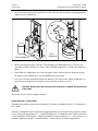
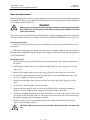
4. Elevate the platen and place a drum into the unit. Be sure that the drum is resting against the
drum stops (see illustration).
Open
Counter
Clockwise
Drum Loading
Vent
Operation
5. Before lowering the platen, open the vent assembly (see illustration above). Unscrew the
vent knob counter-clockwise to release. This will allow trapped air to escape from under the
platen.
6. When adhesive temperatures are ready, the platen can be lowered into the drum by placing
the platen control (RAM) lever into the DOWN (lower) position.
7. Leave the vent open until molten material appears at the vent nozzle. Allow enough flow to
insure the air is purged. Once purged, screw vent knob clockwise to lock.
CAUTION: DO NOT leave the vent open during operation or material will flood the top
of the platen.
The system is now ready for pump operation.
System Operation, Pump Output
The unloader system has two modes of operation: “Pressure on Demand” mode or “Constant Pressure” mode.
“Pressure on Demand” mode is used with an application device or reservoir that provides a contact
close to activate the pump motor, i.e., a hand-held applicator. “Constant Pressure” mode is used with
a valved applicator that requires a constant pressure for proper operation, i.e., a valve heater or an
automatic applicator (head). “Constant Pressure” is also used for a bulk feed application.
Page 3--5
Revised 4/01
ITW Dynatec c. 2000
DYNADRUM 55 UNLOADER Manual #21-06
Pump Output, “Pressure on Demand”
1. With the system ON, a fresh drum of material installed and at operating temperature, turn
the pump motor control to MANUAL.
2. Point the hand-held applicator into a container and activate the trigger. When hose and
handgun are purged of entrapped air and material is flowing in a steady stream, adjust either
the pump/ motor speed or air pressure to obtain desired flow.
WARNING
Be sure hand-held applicator (handgun) is pointed away from personnel as entrapped
air may cause material to splatter.
3. If a second hand-held applicator is used, point it into a container, pull trigger and purge.
When the material is flowing in a steady stream, have an assistant activate the first handgun.
With both handguns activated, adjust either the pump/ motor speed or air pressure to obtain
desired flow.
The system is now ready for operation.
CAUTION: Whenever leaving the system in a standby mode, place the platen elevator
control in the middle position.
Pump Output, “Constant Pressure”
1. With the system ON, a fresh drum of material installed and at operating temperature, turn
the motor control to MANUAL or AUTO.
Note: for AUTO use a 0-10 VDC signal must be used for flow.
2. Activate the applicator(s) or open the bulk feed valve.
3. When material is flowing in a steady stream, adjust either the pump/ motor speed or air
pressure to obtain desired flow.
4. Monitor the system status lights to determine when to replace an empty drum. See page 4-6
for details.
Drum Unloading
1. When drum is exhausted of material (adhesive), raise the platen (follower plate) out of the
drum by placing the platen control lever in the RAM UP position. At the same time, depress
and hold in the follower blow-off button (which activates the air injection valve) until the
platen has risen out of the drum.
If the drum begins to rise with the platen, momentarily place the platen control lever in the
middle position. Normal operation will require holding the blow-off button in while working
the platen control lever between the UP and middle positions.
CAUTION: Do not allow the drum to rise with the platen as it may cock off center and be
difficult to remove.
CAUTION: Do not attempt to raise or lower platen unless platen is at operating
temperature.
Page 3--6
Revised 4/01
ITW Dynatec c. 2000
DYNADRUM 55 UNLOADER Manual #21-06
2. When the platen is in the full UP position, rock the drum out of the unit and replace with a
new one.
WARNING
DO NOT grasp the drum by its lip as severe burns from molten material may occur.
3. Unscrew and remove the vent assembly.
4. Lower the platen into the new drum by placing the platen control lever in the RAM DOWN
position.
5. When molten material begins to escape from the vent’s port, replace the vent assembly.
Operator Adjustments
DynaControl Controller
All system temperature zone setpoints, standbys, offsets, hi/ low limit deviations, heating sequences,
etc. are programmed through and controlled by an ITW Dynatec DynaControl controller. These
functions and the actual zone temperatures are displayed at the controller’s keypad.
See Chapters 4 & 5 for complete information and programming of the controller.
System Pressure
System pressure is regulated by pump/ motor speed, material viscosity, pressure relief valve setting
and by the motor current limit setting. The motor current limit is factory set and does not require
further adjustment.
The pressure relief valve is typically factory set to 500 psi. It is located on the front side of the transfer
block (on top of the platen).
WARNING HIGH PRESSURE
The following procedure will require the adhesive to be at a high temperature and the
application system to have substantial pressure. Safety glasses, insulated gloves and
long-sleeved protective clothing must be worn to prevent the possibility of serious injury from the hot adhesive.
Prior to pressure relief valve adjustment, turn the system ON and raise the temperatures of all components to normal operating temperatures. At the controller, first set the motor speed to “0” so that
the gearmotor is not turning. Then set the motor ON to desired operating speed. Locate the pressure
relief valve’s adjustment screw and loosen its lock nut. Open (actuate) the valves on the applicators
in order to fill them with adhesive and purge air from the system. Then close the valves to stop adhesive flow.
To adjust the pressure relief valve: (see following illustration) with an allen wrench, turn the adjustment screw counterclockwise to decrease pressure or clockwise to increase pressure. After desired
pressure is achieved, tighten the lock nut.
CAUTION: Maximum operating pressure should not exceed 1000 psi. DO NOT set the
adjustment screw fully clockwise (closed) or serious pump damage will result.
Page 3--7
Revised 7/06
ITW Dynatec c. 2000
DYNADRUM 55 UNLOADER Manual #21-06
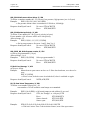
Adjustment screw
Lock nut
Mounting nut
Pressure Relief Adjustment
(Gear Pump Model shown)
Platen Retract Air Pressure
To aid in removal of the platen from the drum it is necessary to create a positive pressure in the drum.
This is accomplished by manually injecting air as the platen is raised. Air pressure is controlled by
an air regulator located on the left side of the platen. Pressure should not exceed 15 psi.
Inlet Pump Pressure Regulator (Optional Piston Pump Models Only)
When adhesive demand changes, the source pressure may reguire adjusting. This can be done manually by turning the handle of the regulator mounted on the piston pump (for an illustration of the
location of this handle, see page 10-7 of this manual).
Page 3--8
Revised 4/01
ITW Dynatec
An Illinois Tool Works Company
Adhesive Application Solutions
ITW Dynatec c. 2000
DYNADRUM 55 UNLOADER Manual #21-06
ITW Dynatec c. 2000
DYNADRUM 55 UNLOADER Manual #21--06
Page 4--1
Revised 4/01
Chapter 4
DynaControlä CONTROLLER SET-UP
Temperature Control Functions in General
The DynaControl microprocessor-based proportional temperature control in the unloader performs a
number of functions that help to maintain adhesive setpoints in all temperature zones of the system.
It maintains permanent system values (fixed proportional and integration values that have been programmed at the factory, such as the maximum temperature setpoint). It enables the user to program
temperature settings and heater on/off sequencing that are appropriate to a specific application. It displays all programmed values, and it includes self-diagnostic malfunction alerts and failure alarms.
Note: Some DynaControl functions are direct temperature conversions between degrees Celsius and
Fahrenheit. Other parameters are independently selected values.
Defining DynaControl Temperature Control Terms
Adhesive Temperature Control Range
The temperature limits within which the unit, hoses and applicators may be programmed and maintained.
CPU Module
The central processing unit (CPU) of the microprocessor temperature control.
Cold Start
When the unit resets itself to default setting due to either a malfunction or to a deliberately initiated
cold start procedure. When the unit is turned ON via the Main Power Disconnect Switch.
Default Settings
The factory-set programmable system values that will be in effect if the user does not enter new values. The controller will revert to its defaults whenever it is reset. The DynaControl controller’s defaults are listed in this chapter.
Error Indication Alarms
Alarms which indicate that the programmed over-temperature values have been exceeded for one or
more temperature zone. Alarms may also indicate an open or short-circuited sensor.
Mechanical High-Temperature Protection
A mechanical, redundant thermostat located on the manifold.
Microprocessor-based Proportional Temperature Control
The built-in control system that controls, monitors and displays all system temperature values.
cont.
Page 4--2
Revised 4/01
ITW Dynatec c. 2000
DUNADRUM 55 UNLOADER Manual #21-06
Over-Temperature Setpoint
The programmable temperatures that will cause alarms (blinking up and down display arrows) to
occur when those temperatures are exceeded. Power is not disconnected, the READY contact opens
and the alarm contact opens. If an external alarm has been connected, it will activate. The overtemp setpoint is the upper limit of the ready temperature range of each zone.
PC Link
Also referred to as remote I/O interface, this is a DynaControl controller option that allows monitoring and programming from a customer-provided PLC (programmable logic controller) or a PC
(personal computer).
P-I Loop
A temperature control loop which bases heater output proportional (P) to the difference betweeen
setpoint and actual temperature and combines it matematically with a time (I = integral) factor.
Power I/O PCBs
The Power I/O printed circuit board (PCB) provides control signals to, and monitoring signals
from, all the temperature zones in the unit’s system.
RTD Sensors
The standard Dynamelt system uses 100-ohm platinum resistance temperature detector sensors for
all temperature controls. As an option, the unit can be configured for 120-ohm nickel sensors.
Ready Temperature
The programmable temperature, on gear pump models, which allows the pump to turn ON. The default ready temperature range is a deviation of ± 20°C (± 36°F) from the setpoint. The setpoint minus the deviation is the low limit of the range, and the setpoint plus the deviation is the high limit of
the range.
Recipe
A program recipe is a set of temperature setpoints and parameters which the user has programmed
and wishes to store in the controller for future use. Up to four recipes may be stored in the DynaControl controller.
Sequential Heating
The heating sequence which allows the slower-heating hopper to reach operating temperature without unnecessary use of electricity for faster-heating hoses and applicators. Sequential heating is the
time period during which the hoses and applicators remain OFF while the unloader’s zones heat up.
Hoses and applicators may be independently programmed. If unloader temperatures are above ready
temperature when the unit is turned ON, the hose and applicator
cont.
ITW Dynatec c. 2000
DYNADRUM 55 UNLOADER Manual #21--06
Page 4--3
Revised 4/01
sequence is bypassed and they will be turned ON. The heat up sequence is restored after Standby
is turned from ON to OFF. Sequential heating is not needed for most applications and can delay
total system warm-up time.
Standby Condition
The system condition where the unit, hose and head temperatures are maintained at predetermined reduced temperature values. Standby temperatures are set lower than setpoint temperatures
in order to reduce adhesive degradation and energy consumption when the system is temporarily
inactive, and to permit rapid system warm-up when run condition is selected.
Setpoint
Programmable temperatures that have been selected for the platen, manifold, hoses, applicators
or auxiliary zones.
Setpoint Limitation
This is a universal maximum temperature for all zones. The programmer cannot program a temperature setpoint higher than the setpoint limitation.
System Logbook
This is the controller’s record-keeping function. It contains the DynaControl’s list of the last
1,000 controller events, its Data Logger which records the last 1000 lines of selected actual temperatures and a counter which records the system’s elapsed hours.
Temperature Zone Enable
The temperature zone enable allows the operator to disable unused temperature zones in such a
way that they do not ever appear on the controller’s display and heating is switched OFF.
Temperature Zone Offset
Due to the separation between the heaters and sensors in some systems, the controller can be programmed to display a temperature for a zone which is different from the sensor’s actual temperature. The temperture zone offset mathematically corrects for these temperature differences. Each
zone may have an individual offset.
Page 4--4
Revised 4/01
ITW Dynatec c. 2000
DUNADRUM 55 UNLOADER Manual #21-06
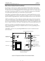
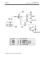
Error Indication & Alarms
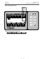
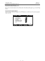
Error Indication (Blinking Up and Down Arrows)
The following illustration shows the display screen when one or more error indication conditions
occur. The conditions that will trigger an error indication are:
a. When the platen, manifold, hose, valve heater or auxiliary zone has exceeded its
selected over-temperature setpoint, which is the setpoint plus its high/low alarm
setting, or when it is below its selected under-temperature setpoint, which is the
setpoint minus its high/ low alarm setting. In these cases, heater power will not be
switched off.
b. When a platen, manifold, hose, valve heater or auxiliary zone sensor has an open
circuit. In this case, heater power will be switched off.
Blinking down arrow indicates undertemp.
Blinking up arrow indicates overtemp.
Numeric Entry
Keys
Tue. 3:36 PM
SYSTEM: Alarm
ACTUAL ° F
1
Platen
Manifold
300
299
Hose
Valve Heater
Aux Zone
HOLD
274
2
273
HOLD
3
4
251
?
?
?
HOLD
>
Mot. 1: AUTO 5.3%
SETPOINTS
MOTORS
SYM
ABC DEF
GHI
JKL
MNO
PRS
TUV
WXY
CLEAR
<
Delete
Delete
EnEnter
ter
Arrow
Keys
“?” indicates no sensor (open circuit).
C
>
ABC/123
Page 4--5
Revised 4/01
ITW Dynatec c. 2000
DYNADRUM 55 UNLOADER Manual #21--06
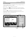
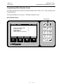
Error Alarms (Message Window)
The display of a message window, as illustrated below, signifies an error alarm. The operator’s response to an error alarm is to press “F4” and to troubleshoot.
If a sensor error alarm or an overtemperature alarm occurs during operation, the controller will
switch off internal power to the heaters and an appropriate error alarm display will appear.
Pressing the “F4” function key acknowledges the error. If several zones display alarms, each must
be acknowledged by pressing “F4”. The alarm display is switched off and the controller then
switches off the faulty zone until the ASU is ready for operation again.
When the actual temperature exceeds the setpoint limitation (plus a tolerance) the overtemperature
alarm window is displayed and main power is switched off.
Examples of Error Alarms
The Overtemperature Alarm indicates that the named
zone has exceeded its programmed setpoint limitation.
The controller will shut off power to the heaters. Press
F4 and troubleshoot the problem.
The Sensor Failure Alarm can indicate either a sensor
open or a sensor short. Sensor open is accompanied by
a blinking up arrow on the actual temperatures display
screen. Sensor short is accompanied by a blinking down
arrow. Press F4 to switch off the named zone,
then troubleshoot the problem.
The Manifold Overtemp Alarm indicates that adhesive
temperatures at the manifold have exceeded the
setting of the mechanical (redundant) thermostat.
Press F4 and troubleshoot the problem.
The Communication Error Alarm indicates an internal
failure, unrelated to zone temperatures. Call ITW
Dynatec for assistance.
Overtemperature
Zone Name
##
Sensor Failure
Zone Name
##
Manifold Overtemp
Communication error
Page 4--6
Revised 4/01
ITW Dynatec c. 2000
DUNADRUM 55 UNLOADER Manual #21-06
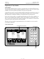
System Status Lights
The stack light(s) mounted on the unloader’s control box assembly allows
remote monitoring of the unloader’s adhesive level status.
The lower, green light illuminates when there is sufficient adhesive in
the drum to run. The optional middle, amber light indicates that the adhesive
level in the drum is low. The upper, red light illuminates only in an alarm
condition (the drum is empty) and is accompanied by an audible alarm. The
audible alarm is housed within the upper (black) section of the stack.
Audible
Alarm
Red
No
Adhesive
Amber
Optional
Low
Adhesive
Green
Sufficient
Adhesive
When the red light and alarm are activated, the controller screen informs the operator that the
“Drum is Empty”. The controller then puts the unloader in setback (standby) mode, lowering adhesive temperature and stopping the pump. When this occurs, the operator must reset the alarm (F4),
install a fresh drum of adhesive, press F2 (Motor Menu) and then press F3 to re-start operation.
Settings for a Typical Operation
Note: The values given here are approximate settings for a typical packaging operation. The values
you choose will be based on the type of equipment and adhesive you are using and the nature of
your particular operation.
If Application Temperature is 177°C (350°F):
∙
Hose and Valve Heater temperature: 177°C (350°F).
∙
Platen and manifold setpoint temperature: 163°C (325°F).
∙
Hi/ Lo limit deviation: 12°C (20°F).
∙
ASU operating range: 149°C to 177°C (300°F to 350°F).
∙
Standby condition temperature (deviation): 30°C (50°F).
∙
Manifold over-temperature setpoint : 177°C (350°F)
∙
Mechanical thermostat (for the manifold) over-temperature: 219°C (425°F)
For most operations, temperature fluctuations will be very small and of short duration. For these
reasons, the settings above are recommended.
ITW Dynatec c. 2000
DYNADRUM 55 UNLOADER Manual #21--06
Page 4--7
Revised 4/01
System Values That Are Factory Programmed (not customer programmable)
∙
Minimum setpoint value: 10°C (50°F).
∙
Maximum setpoint value (Setpoint limitation): 218°C (425°F).
”
”
”
for high temp mode enabled units: 232°C (450°F)
∙
Maximum alarm deviation: 50° (C or F).
∙
Minimum alarm deviation: 5° (C or F).
∙
Maximum standby temperature: 150° (C or F) less than setpoint.
∙
Minimum standby temperature: 30° (C or F) less than setpoint.
∙
“Actual” temperature indication range: 0°C to 260°C (32°F to 500°F).
Customer Programmable Values Preset At The Factory
ITW Dynatec can set the controller’s system values to customer’s specs, if provided.
If customer’s specs are not provided, the following values will be entered into the DynaControl
controller at the factory. They may be changed by reprogramming through the keypad. (These are
not the “default” settings, see following section).
∙
Valve heater and hose setpoints: varies from 138 to 149°C (280 to 300°F).
∙
Platen setpoint: 143°C (290°F).
∙
All zones are switched off, except for the platen and manifold.
∙
Motor rpm: 0 in the “OFF” mode.
∙
Standby: 80°C (140°F) under setpoint.
∙
Hi and low alarms: ± 12°C (20°F) from setpoint.
Page 4--8
Revised 4/01
ITW Dynatec c. 2000
DUNADRUM 55 UNLOADER Manual #21-06
Default Settings of the DynaControl Controller
Default settings are the manufacturer’s preset values to which the system will return if the DynaControl is subjected to an internal memory reset (also referred to as a “re-boot”). While you can
change your programmed values to anything within the system’s limits, the default settings cannot
be changed.
Defaults
∙
Language: English
∙
Setting for Customer Access Code: “9999”.
∙
Temperature setpoint for each zone: - - -
∙
Platen ready temperature: 135°C (270°F).
∙
Over-temperature limit: Your chosen setpoint limitation + 10° C or F.
For example: if your setpoint limitation is 218°C (425°F), then your over-temp limit = 228°C (435°F).
∙
Standby temperature for all zones: 80°C (140°F) lower than programmed setpoints.
∙
Hi/ lo limit deviation for all temperature zones: ± 20°C (36°F).
∙
Temperature zone offset: 0°C (0°F).
∙
Sequential heating: first platen & manifold zones, then hose/ head zones and auxiliary zones.
∙
Setpoint limitation: 218°C (425°F).
∙
Minimum pump speed: 0% of full speed.
∙
Maximum pump speed: 100% of full speed.
∙
Proportional Integral values (P-I values): for Premelt, Hopper and Filterblock temperature
zones, P = 15 and I = 3. For all other zones, P = 12 and I = 2
ITW Dynatec c. 2000
DYNADRUM 55 UNLOADER Manual #21--06
Page 4--9
Revised 4/01
Helpful Tips for the User
∙
When the unit is turned ON, all temperature setpoints and other operating parameters will
be exactly where they were when the unit was turned off.
∙
When the unit is turned ON, all system heaters go ON unless they have previously been set
below 40°C (100°F) (in which case they will be turned OFF) or if sequential heatups have
been set. However, if hopper temperature is above ready temperature when the unit is
turned on, all hose and head sequential heatups will be bypassed and hoses and heads will be
turned ON.
∙
If the system is turned off and then on again, the standby condition will be disabled.
Page 4--10
Revised 4/01
ITW Dynatec c. 2000
DUNADRUM 55 UNLOADER Manual #21-06
Serial Protocol for RS232 and RS485 Options, V.5.00M
Specifications
-- RS232C, no handshake
- RS485, 4 wires
-- Baud rate 9600 baud
- Character format 8 databits + 1 startbit + 1 stopbit
- Parity: no parity check
General information
-- DynaControl is always a slave. The controller reacts only when addressed by a master.
- DynaControl responds only when own slave address is received. Slave address is programmable via front panel (PC-LINK Setup).
-- Multi--digit values are transferred most significant digit first.
-- If Hex--Numbers are transferred, do not use capitals (0¼9, a¼f)
- Control characters used:
STX 02
Start of Text
ETX 03
End of Text
EOT 04
End of Transmission
ENQ 05
Enquiry
ACK 06
Positive Acknowledge
NAK 15
Negative Acknowledge
Structure of commands
- Master transmits to DynaControl:
EOT, addr1, addr2, opcode, 0..n data bytes, ENQ
-- DynaControl responds:
STX, 1...n data bytes, ETX
Address Setting
Each telegram sent to the DynaControl contains the slave address. DynaControl responds only if
the received address matches the programmable address.
List of Commands
Writing to DynaControl:
WR_TC
A
WR_TF
F
WR_TO
B
WR_SPS
C
WR_PRA
P
WR_PR
H
WR_PROG_NO
R
FQ
L
Write Temperature Setpoint (Temp Scale Celsius)
Write Temperature Setpoint (Temp Scale Fahrenheit)
Write Hi/Lo--Alarm Temperature Tolerance (+--%)
Write Motor Speed Setpoint (0--99.9% F.S.)
Write Hi/Lo--Pressure Alarm values
Write Priority (Heat up Sequence)
Write Temp. Program Number
Reset Error Message
Reading from DynaControl:
RD_TA
d
Read Actual Temperature
RD_TS
a
Read Temperature Setpoint
RD_TO
b
Read Hi/Lo Temperature Tolerance
Page 4--11
Revised 4/01
ITW Dynatec c. 2000
DYNADRUM 55 UNLOADER Manual #21--06
RD_SPS
RD_SPA
RD_CST
RD_ZST
RD_PR
RD_LSP
RD_PRA
RD_PROG_NO
c
e
f
i
g
l
p
r
Read Motor Speed Setpoint
Read Actual Motor Speed (RPM)
Read System Status
Read Temperature Status
Read Actual Pressure
Read Line Speed Input
Read Hi/Lo Pressure Alarm values
Read Temp. Program Number
Detailed Description of Commands
WR_TC Write Temperature Setpoint, ’A’, 41H
Temp. Scale Celsius
WR_TF Write Temperature Setpoint, ’F’, 46H
Temp. Scale Fahrenheit
To follow: zone number (2 byte) 01...48 + setpoints (n x 4 bytes ASCII)
Adding 1000 to setpoint will deactivate this zone. Subtracting 1000 will activate again.
EOT,0,1,A,0,4,0,1,6,0,1,1,8,0ENQ - > Zone no. 4 on unit with address 01
is set to 160°C, no. 5 is set to 180C but temporarily deactivated.
Response from DynaControl:
No error: STX,ACK,ETX
Error:
STX,NAK,ETX
Example:
This command will select the temperature scale for the controller.
WR_TO Write Temperature Hi/Lo- Tolerances, ’B’, 42H
To follow: zone number (2 bytes) 00...48 + Temp Tolerance (2 bytes)
zone number = 00: Set tolerance of all zones.
Tolerance: Deviation (plus/minus) from setpoint to get Hi/Lo - indication (Alarm window)
Allowed range: 5 to 50
Example:
EOT,0,1,B,1,2,2,0,ENQ
--> Set tolerance for zone 12 on slave
address 01 at +/--20°
Response from DynaControl:
No error: STX,ACK,ETX
Error:
STX,NAK,ETX
WR_SPS Write Motor Speed Setpoint, ’C’, 43H
To follow: motor number 00...06 (2 bytes), motor speed (nx 4 bytes)
If motor number = 00: all motors will be set to this speed
- > Speed Setting takes place in steps of 0.1% of Full Speed
Allowed Range:
0 to 1000 (0 to 100.0%)
Example:
EOT,0,1,C,0,2,5,0,0,ENQ - > Set pump speed no.2 on unit address 01
to 50 %
Response from DynaControl:
No error: STX,ACK,ETX
Error:
STX,NAK,ETX
Page 4--12
Revised 4/01
ITW Dynatec c. 2000
DUNADRUM 55 UNLOADER Manual #21-06
WR_PRA Write Pressure Alarm Values ’P’, 50H
To follow: transducer number 00...23 (2 bytes), low pressure, high pressure (n x 4+4 bytes)
Example:
EOT,0,1,P,0,2,0,2,0,0,1,0,0,0,ENQ
- > Set pressure alarm values on transducer #2 200=low, 1000=high
Response from DynaControl:
No error: STX,ACK,ETX
Error:
STX,NAK,ETX
WR_PR Write Heat up-Priority, ’H’, 48H
To follow: Zone number 00...48 (2 bytes), priority (n bytes)
If zone number = 00: all zones will be set to this priority
Allowed range: 1/2
Example:
EOT,0,1,H,0,1,1,1,2,2,2,2,2,2,ENQ
- > Set heat up sequence: first zone 1 and 2, then 3 to 8
Response from DynaControl:
No error: STX,ACK,ETX
Error:
STX,NAK,ETX
WR_PROG_NO, Write Program number, ’R’, 52H
to follow: program number (1 byte)
Allowed range: 1 to 4
Examples:
EOT,0,1,R,3,ENQ Select program number 3
Response from DynaControl:
No error: STX,ACK,ETX
Error:
STX,NAK,ETX
FQ Quit Error Message, ’L’, 4CH
no bytes to follow
Example:
Master detects open sensor on slave no.2. Slave has shut down, error has to be
reset.
EOT, 0,2,L,ENQ
- > Error is reset, defective zone is switched off, slave is switched on again.
Response from DynaControl:
NSTX,ACK,ETX
RD_TA Read Actual Temperature, ’d’, 64H
To follow: zone number (2bytes) 00....48
zone number = 00: all available actual temps are transmitted.
Example:
EOT,0,1,d,00,ENQ --> All actual temps on unit address 01 are read
Response from DynaControl :
STX, Act.Temps(1...n x 4 bytes), ETX
Error:
STX,NAK,ETX
Sensor shorted:
STX,1999,ETX
Sensor open:
STX,0999,ETX
Example:
STX,0155,0165,0159,0160,0999,0159,0160,1999,ETX
- > Unit has 8 zones. Zone 5 shows shorted sensor, zone 8 has open sensor.
ITW Dynatec c. 2000
DYNADRUM 55 UNLOADER Manual #21--06
Page 4--13
Revised 4/01
RD_TS Read Temperature Setpoint, ’a’, 61H
To follow: zone number (2bytes) 00...48
zone number = 00: all available setpoints are transmitted
EOT,1,2,a,0,2,ENQ - > Read setpoint of zone no.2 on unit with
address 12
Response from DynaControl:
STX, Setpoint (1..n x 4 bytes), ETX
Example:
If first digit is 1, zone is deactivated.
Example: Setpoint = 1160 --> Setpoint = 160°, zone is deactivated.
RD_TO Read Temperature Hi/Lo- Tolerances, ’b’,62H
To follow: zone number (2 bytes) 00...48
zone number = 00: tolerances off all zones are transmitted
Example:
EOT,0,1,’b’,1,2,ENQ - > Read tolerance from zone 12 on Unit with
address 01
Response from DynaControl:
STX, Tolerance (1..n x 2 bytes), ETX
Error: STX, NAK,ETX
RD_SPS Read Motor Speed Setpoint, ’c’, 63H
To follow: motor number 00...06 (2 bytes).
If motor number = 00: all motor speed setpoints will be transferred.
Response from DynaControl:
STX, Motor speed (1..n x 4 bytes),ETX
Example:
EOT,0,1,’c’,0,1,ENQ - > Read motor speed from motor 1 on unit with
address 01
RD_SPA Read Actual Motor Speed, ’e’, 65H
To follow: motor number 00...06 (2 bytes).
If motor number is 00, actual speed of all motors is transferred.
Example:
EOT,0,2,’e’,0,1,ENQ --> Read motor speed number 1
Response from DynaControl:
STX, 4 bytes, ETX
- > actual speed has to be scaled to real RPM (sczle factor = gear ratio)
RD_CST Read System Status, ’f’,66H
No bytes to follow
Example:
EOT,0,2,f,ENQ
Response from DynaControl:
STX, Status (4 bytes),ETX
Status: the 4 bytes build a number 0 to 2047. Each bit represents dedicted information:
Bit 0: 1 = Controller is switched on
Bit 1: 1 = a High Alarm is present
Bit 2: 1 = a Low Alarm is present
Bit 3: 1 = Controller is switched to standby mode
Bit 4: 1 = Pump Enable Thermostat is closed ( = pumps are enabled)
Page 4--14
Revised 4/01
ITW Dynatec c. 2000
DUNADRUM 55 UNLOADER Manual #21-06
Bit 5: 1 = 7 Day Scheduler is active
Example:
STX,0037,ETX
- > 0037 = 0025 hex: Scheduler active, low temperature
alarm
RD_ZST Read Temperature Status, ’i’,69H
To follow: zone number (2 bytes) 00...48
zone number = 00: status of all zones is transmitted
Example:
EOT,0,3,i,0,0,ENQ --> All zone status are requested from
slave address 03
Response from DynaControl:
STX, Status,ETX
Status: 0
Zone is deactivated
1
zone is activated but waiting for enable (heat up sequence)
2
zone is activated and heating is enabled but tolerance is not reached.
3
Zone is activated, enabled and has reached tolerance window
4
Zone is in low temp condition
5
Zone is in high temp condition
6
Sensor shorted
7
Sensor open
RD_PR Read Pressure Value, ’g’,67H
To follow: transducer number 00...12 (2 bytes).
If transducer number is 0: all pressure values are transferred
Example:
EOT,0,2,g,0,0,ENQ - > Read all pressure values from slave address 02
Response from DynaControl:
STX, n x 4 bytes, ETX
Depending on the controller’s configuration, pressure will be in PSI or BAR scale.
RD_LSP Read Line Speed Input, ’l’ , 6CH
To follow: motor number 00...06 (2 bytes)
If motor number = 00: all line speed inputs will be transferred.
--> line speed range: 0...10V = 0...100.0%
Response from DynaControl:
STX, Line speed (1..n x 4 bytes),ETX
Example:
EOT,0,1,’l’,0,1,ENQ - > Read line speed motor 1 on unit with
address 01
RD_PRA Read Hi/Lo Pressure Alarm Value, ’p’, 70H
to follow: transducer number 00...12 (2 bytes)
If transducer number is 00: all pressure alarm values are transferred.
Example:
EOT,0,2,p,0,0,ENQ Read all pressure alarm values
Response from DynaControl:
STX, n x 4+4 bytes, ETX
RD_PROG_NO, Read Program Number ’r’, 72H
to follow -Examples:
EOT,0,2,r,ENQ Read program number on slave #2
Response from DynaControl:
STX, program number (1 byte), ETX
Page 5--1
Revised 8/06
ITW Dynatec c. 2000
DYNADRUM 55 UNLOADER Manual #21--06
Chapter 5
PROGRAMMING INSTRUCTIONS
FOR V5.16DU DynaControl™ CONTROLLER WITH EXPANDED KEYPAD
Controller Safety Consideration
DANGER HIGH VOLTAGE
Never open the control panel without switching off the main disconnect switch
to ensure that it is disconnected from its power source.
The printed circuit boards should always be carefully removed. DO NOT handle the boards except by their edges. Read the section on PCBs in Chapter 7 of this manual for further cautions.
Software Version
You can determine the software version of your controller by noting it when it comes up on the display at startup:
* * * ITW Dynatec * * *
M-Control V 5.16DU
Drum Unloader Software Version
Page 5--2
Revised 8/06
ITW Dynatec c. 2000
DUNADRUM 55 UNLOADER Manual #21-06
Display & Keypad Reference
System Status:
Ready
Heat up
Alarm
Standby
Scheduler Active Indicator
Day of Week
Time of Day
1
Platen
Manifold
300
299
Hose
Valve Heater
HOLD
274
2
273
HOLD
3
4
251
>
?
HOLD
Mot. 1: AUTO 5.3%
SETPOINTS
On/Off Key & LED
Service Key
Numeric Entry
Keys
Tue. 3:36 PM
SYSTEM: Alarm
ACTUAL ° F
Scheduler Key:
Standby
Day/Date Clock
7-Day Scheduler
Program Recipes
MOTOR
SYM
ABC DEF
GHI
JKL
MNO
PRS
TUV
WXY
CLEAR
<
Delete
Delete
EnEnter
ter
C
>
ABC/123
Arrow Symbol = use to enter
Keys a space, colon, dash,
dot, “Q” or “Z” into text
Continued
< >
Display & Function Keypad
(Actual Temps Screen shown as example)
1, 2, 3
Press Enter to activate or confirm
Enter a numeric value with 0 - 9 keys
A,B,C
Enter a letter on the alpha-numeric
Enter
0 = toggle from numeric (1,2,3) to alphabetic (A,B,C) entry
Numeric
Keypad
This item or this screen is locked
F
This item is factory setup* only
< > Press button C to see more zones
HELP Screen (F4 on Actual Temperatures Screen)
* Factory Setup = can be
modified by ITW Dynatec’s
technicians only
Page 5--3
Revised 8/06
ITW Dynatec c. 2000
DYNADRUM 55 UNLOADER Manual #21--06
Display Reference, cont.
Black box = item is selected for programming
System Status Line
SYSTEM: Alarm Lo
SETPOINTS
Zone Names
Information lines
Numeric Entry
Keys
Tue. 3:36 PM
1
Platen
Manifold
300
299
2
Hose
Valve Heater
Aux Zone
274
-- -- --
273
-- -- --
°F
INFO: UPPER GRID
Set: 300°F Act: 300°F
3
4
251
-- -- --- -- --
>
273
-- -- --- -- -Zo: 1
Tol:±30°F
1, 2, 3
RETURN
Function keys:
Scroll Up, Down or Right
“Return” to last screen
Go to “Motor” screen
Toggle “On/Off”
“All _ _ _” = all in category
“ABC/abc” = letter case
“CLR Line” = clear entire line
“Clear” an alarm or message
“Copy” = copy word(s) to a clipboard
“Paste” = paste copied words into text
Screen continues,
press “C” to view
Zone Status:
### = Temperature
HOLD = In priority queue,
waiting for release
= Over temp
= Under temp
-- -- -- = Off
? = no sensor
Zo: # = this is the controller’s identification #
for each zone
Programming entry:
1,2,3 = numeric only
A,B,C = alpha only
Function keys:
F1, 2, 3, 4
Setpoint Programming Screen
SYSTEM: Ready
Motor Mode
1 AUTO.
User-chosen name
INFO: PUMP
Function key:
“Manual”, “Automatic” or
“Stop” = motor modes
“Restart” motor
MANUAL
Tue.
Set
%
Min
%
5.0
5.0
AUTOMATIC
Max
%
80.0
3:36 PM
Actual
RPM
RUN
87
STOP DeleteRETURN
Enter
Arrow
Motor Programming Screen
Keys
Motor Programming Screen
Actual RPM =
optional display
(tach generator
required)
Lock = this screen is
locked from further
programming
Page 5--4
Revised 8/06
ITW Dynatec c. 2000
DUNADRUM 55 UNLOADER Manual #21-06
Basic Programming Sequence: Quick Reference
Follow the screen-by-screen steps outlined in the remainder of this chapter for complete setup and
programming instructions. Thereafter, use this page as a “quick reference”.
Press
Turn Controller On
x3, 2 Language Selection
x1, 8 Temperature Scale Selection
F4
Actual Temperatures:
F1 To Program Setpoints
F2 To Program Motor*
x1
x2
x3
Service Functions (1 of 3):
1 = High Low Temperature Deviation
2 = Setback Temperature
3 = Setback Time Delay
4 = Setpoint Limitation
Service Functions (2 of 3):
1 = Customer Zone Names
2 = Power On Configration
3 = Factory Defaults
4 = Keypad Locking
5 = PC Link
6 = Temperature Offset
7 = Sequential Heating
8 = Temperature Scale
9 = Change Security Lock or Access Code
6 = Language
7 = LCD Contrast
8 = System Logbook
9 = Change Security Lock
Service Functions (3 of 3):
(These functions are factory-programmed only)
To Program Scheduler
1 = Manual Standby Activation
2 = Time & Date Clock
3 = Program 7-Day Scheduler
4 = Select Program Recipes
5 = Manual Scheduler Activation
End
* The controllers for the Drum Unloader’s Piston Pump Models does not contain any motor
screens or references to “motor” or “RPM”.
Page 5--5
Revised 8/06
ITW Dynatec c. 2000
DYNADRUM 55 UNLOADER Manual #21--06
Controller Setup
Below is the step-by-step process of setting up the controller.
Note: Whenever an Access Code is required, enter your individual code. The default code is 9999. If
you have lost your code, call ITW Dynatec Customer Service: 1-800-538-9540 (in the USA) or contact your local repsentative.
Turn the Controller ON
Turn the controller ON using the units main On/ Off switch.
Language Selection
English is the default language. If you desire another language (choices are German, French, Italian, Spanish, Swedish, Portugese, Japanese and Dutch), make your selection:
Press the Service Key
two times to advance to Service Functions page 2/3.
Press #6 on the numeric keypad, followed by Enter
.
Press the numeric key of your language choice, followed by Enter
(OR Scroll
to your choice, then press Enter
.
.
Temperature Scale Selection
Press the Service Key
twice to advance to Service Functions page 1.
Press #8 on the numeric keypad, followed by Enter
.
Toggle to make your choice between °C scale or °F scale. Press
Press Return (F4) to Go to the Actual Temperatures Screen
Enter.
Page 5--6
Revised 8/06
ITW Dynatec c. 2000
DUNADRUM 55 UNLOADER Manual #21-06
Actual Temperatures Screen
The Actual Temperatures Screen serves as the controller’s main menu. From here you can go to
any other screen. The Actual Temperatures Screen is also the most useful screen to display for
monitoring purposes.
System Status
SYSTEM :
Arrow
ACTUAL
Keys
Platen
Manifold
Ready
° F
Scheduler Key
7-Day Scheduler Active
Tue.
1
2
Service Key
3:36 PM
3
4
>
300
299
274
Hose
Valve Heater
HOLD
273
HOLD
251
?
HOLD
Mot. 1: AUTO 5.3%
SETPOINTS
MOTOR
SYM
ABC DEF
GHI
JKL
MNO
PRS
TUV
WXY
HELP
<
Delete
Enter
C
>
ABC/123
Motor Info Line
Use of the Actual Temperatures Screen
Press This
Function Key
Controller
On/Off Key
To:
On/Off
Toggle display, motors and heaters power ON or OFF
Setpoints (F1)
Go to the setpoints programming screen
Motor (F2)
Go to the motor programming screen
Help (F4)
Go to the Help screen.
Service
Go to the first of the three service screens
Scheduler
Go the the Main Scheduler screen
ITW Dynatec c. 2000
DYNADRUM 55 UNLOADER Manual #21--06
Page 5--7
Revised 8/06
Use of the Actual Temperatures Screen, cont.
Programming Sequence (details on following pages)
1. Press Setpoints. After programming all of your temperature setpoints, return to the Actual Temperatures Screen.
2. Press Motor. After programming the motor, return to the Actual Temperatures Screen.
3. Press Scheduler Key to program the following functions: Standby, Time & Date Clock, 7-Day
Scheduler and/ or Program Recipes.
4. Press Help to view the Help screen (illustrated on page 5-2).
Monitoring:
1. System Status display describes system status as one of the following:
a. System Heat up: power is ON but zone temperatures have not risen to setpoint range.
b. System Ready: all zones have reached setpoint temperatures.
c. Alarm: a temperature zone is out of its setpoint tolerance range. An overtemp alarm is indicated by an upwards arrow next to a temperature. An undertemp alarm is indicated by a downwards arrow next to a temperature.
d. Alarm Lo: the programmed low level deviation is preventing operation due to an actual low
temperature condition.
e. Standby: the system is in a programmed standby state.
2. Actual Temperatures or Zone Status of all zones is displayed:
a. ###: a three-digit number indicates a zone’s actual temperature.
b. HOLD: zone is waiting for release. Zones with higher priority have been released.
c. Arrow up: zone is over temperature.
d. Arrow down: zone is under temperature.
e. ?: there is no sensor. Zone needs troubleshooting.
f. >: there are more temperature zones not seen on the current display. To view them, press C
on the numeric keypad (bottom row, first key).
3. 7-Day Scheduler Active display shows that the 7-Day Scheduler is programmed and in use.
4. Motor Info Lines indicate motor mode (”Auto” on the illustration on page 5-6) and external reference percent.
5. If the optional Actual RPM display (shown on page 5-3) is installed, actual pump rpm may be
monitored.
Page 5--8
Revised 8/06
ITW Dynatec c. 2000
DUNADRUM 55 UNLOADER Manual #21-06
Setpoints Programming Screen
SYSTEM :
Arrow
SETPOINTS
Keys
Platen
Manifold
Hose
Valve Heater
Ready
°F
Tue.
1
2
300
350
275
275
INFO: UPPER GRID
Set: 300°F Act: 300°F
275
275
3:36 PM
3
4
275
275
275
275
Zo: 1
Tol:±30°F
SYM
ABC DEF
GHI
JKL
MNO
PRS
TUV
WXY
RETURN
<
Delete
Enter
ABC/123
Controller identification number for zone
Zone Info Lines
Alternative programming function keys:
All _ _ _
C
>
ON/OFF
CLEAR
Page 5--9
Revised 8/06
ITW Dynatec c. 2000
DYNADRUM 55 UNLOADER Manual #21--06
Use of the Setpoints Programming Screen
Each of the temperature zones is programmed individually by using the function keys as follows:
Press This
Function Key
To:
Scroll Up, Down or Right (F1, 2, 3)
Select each zone’s setpoint
Return (F4)
Return to the Actual Temperatures Screen
(Enter)
Enter a numeric value
All - - - (F1)
All zones in a category (ie, All Hoses, All Heads,
etc.)
On/Off (F3)
Toggle a zone on or off
Clear (F4)
Eliminate an error message or alarm
Programming
1. Scroll to the first temperature zone setpoint you desire to program.
2. On the numeric keypad, enter the desired setpoint value.
3. Press Enter
.
4. Scroll to the next setpoint to be programmed and repeat steps 2 and 3.
Notes:
a. To turn a zone OFF: scroll to zone, press Enter to select, press ON/OFF (F3).
b. When turning a switched-off zone back ON, it will retain its previous setpoint.
c. To change all zones in a category (ie, all hoses, or all aux zones, etc.): scroll to one item in
that category, enter desired value, then press F1 (this does not apply to zones which are turned
OFF).
Monitoring
1. “Zo #”: the number which appears here is the controller’s identification number for this zone.
This number cannot be changed by user.
2. The Zone Info Lines indicate the user-defined zone name (programmed on page two of the Service Key functions, menu item 1), the zone’s setpoint, the zone’s actual temperature, the zone’s
tolerance (programmed on page 1 of the Service Key functions, menu item 1) and the zone’s identification number.
Page 5--10
Revised 8/06
ITW Dynatec c. 2000
DUNADRUM 55 UNLOADER Manual #21-06
Motor Programming Screen
Optional
RPM
Display
SYSTEM :
Arrow
Keys
Ready
Tue.
Motor Mode
Set
%
Min
%
1 AUTO.
5.0
5.0
Max
%
80.0
Actual
RPM
RUN
INFO: PUMP
MANUAL
3:36 PM
87
1, 2, 3
AUTOMATIC
STOP
SYM
ABC DEF
GHI
JKL
MNO
PRS
TUV
WXY
RETURN
<
Delete
Enter
Alternative programming function keys:
RE-START
RETURN
C
>
ABC/123
ITW Dynatec c. 2000
DYNADRUM 55 UNLOADER Manual #21--06
Page 5--11
Revised 8/06
Use of the Motor Programming Screen
Program the motor by using the function keys as follows:
Press This
Function Key
To:
Re-Start (F4)
To re-start motor
Manual (F1)
Choose Manual Mode for the selected motor
Automatic (F2)
Choose Automatic Mode for the selected motor
Stop (F3)
Choose Stop Mode for the selected motor
Return (F4)
Return to the Actual Temperatures Screen
(Enter)
Enter a numeric value
Programming
1. Press Manual, Automatic or Stop as desired motor mode. Press Enter.
2. If in Manual mode, enter pump speed ##.# in the Set % column:
a. Use numeric keypad to enter desired rpm value.
b. Press Enter.
3. If in Automatic:
a. Scroll to Min % to program minimum pump speed. Enter value as described above.
Note: typically, at 0 volts, this value will be between 0 and 10% (default = 0%).
b. Scroll to Max % to program maximum pump speed. Enter value as described above.
Note: typically, at 10 volts, this value will be between 0 and 100%, depending on motor
installed on ASU (default = 100%).
Monitoring
1. RUN indicates the pump/ motor is enabled.
2. HOLD indicates that the controller is preventing the pump/ motor from running, due to a low
temperature, a standby condition, etc.
2. The Info Line indicates the user-defined name for the selected motor (programmed on page two
of the Service Key functions, menu item 1).
3. If the optional Actual RPM display is installed, actual pump rpm may be monitored. With this
option, the RUN/HOLD column is eliminated. The Actual RPM display is also seen on the Actual
Temperatures Screen.
Page 5--12
Revised 8/06
ITW Dynatec c. 2000
DUNADRUM 55 UNLOADER Manual #21-06
Service Functions Screens
The three Service Function Screens are designated Page 1/3, Page 2/3 and Page 3/3. They are accessed by pressing the Service Key 1, 2 or 3 times.
Functions coded - - are active and require no code to program.
Functions coded with a key
are locked and require entry of a code before programming.
For example, as seen on the diagrammed screen below, Setpoint Limitation is locked from further
programming.
Functions coded
F
are ITW Dynatec factory setups and are not user accessible.
Program the Service Functions as described on the following pages. Many functions are programmed simply by a toggle or by a single numeric entry.
Service Functions Screen Page 1/3
Service Key
SYSTEM :
Ready
Arrow
PAGE 1/3
Keys Hi/Lo Temperature
Standby Temperature
Standby Time Delay
Setpoint Limitation
N/A
Temperature Offset
Sequential Heating
°C / °F
Change Security Lock
Tue.
.
1
2
3
4
5
6
7
8
9
3:36 PM
CODE
------------------------1, 2, 3
SYM
ABC DEF
GHI
JKL
MNO
PRS
TUV
WXY
RETURN
<
Delete
Enter
Alpha/Numeric
Keypad
C
>
ABC/123
Enter
ITW Dynatec c. 2000
DYNADRUM 55 UNLOADER Manual #21--06
Page 5--13
Revised 8/06
Service Functions Screens, cont.
Function #
Press #1 to program High/ Low Temperature Deviation. Enter a numeric value for the first zone
selected. Press Enter to confirm. Scroll to next desired zone and repeat until all zones are programmed. Then Press Return (F4) to return to menu. Note: after entering one value in any category, you may press All xxx. (F1) to change all the items in that category.
The High/ Low Temperature Deviation is a range (±) representing the high and low temperature
limits of each setpoint. During operation, these limits activate the error alarms which alert the operator to over-temp and under-temp conditions in the temperature zones. The smallest deviation
programmable is ±5° (C or F) and the largest is ± 50°.
CAUTION: DO NOT set your low temperature limit below the softening point of
your adhesive or pump damage will result. The softening point of a material is
the lowest temperature at which that material can be pumped.
Press #2 to program Standby Temperature. Enter a numeric value for each category. Press Enter.
Press Return (F4). Note: if the same Standby Temperature is desired for all zones: enter the value,
then press All xxx.
The Standby Temperature is a reduction in temperature by which all the temperature zones will be
reduced in a standby condition. For example, if the platen setpoint is 275° and you program a 100
degree standby temperature, the controller will reduce the platen temperature to 175°. Numerically, the controller will accept any standby temperature within the range of -30°C and -150°C (-30°F
and -150°F).
Press #3 to program Standby Time Delay. Enter a numeric value. Press Enter. Press Return (F4).
The Standby Time Delay allows programming of a delay from the time the “external standby” terminals (for connection, see Chapter 3) are connected until the unit enters its standby mode. The
time delay selected must be in the range from 0:00 (which represents an immediate entry into
standby, i.e. no delay) to 7:59 (seven hours and 59 minutes).
Press #4 to program Setpoint Limitation. Enter a numeric value. Press Enter. Press Return (F4).
The Setpoint Limitation is a universal maximum temperature for all temperature zones (ie, the
overtemperature limit). The controller will not allow the operator to program a higher setpoint
than the value of the setpoint limitation. The default setpoint limitation is 218°C (425°F). The selectable range for the setpoint limitation is 40°C - 232°C (100°F - 450°F).
Function #5 is not active in the present controller configuration. No programming is possible.
Press #6 to program Temperature Offset. Enter a numeric value for the first zone selected.
Press Enter. Scroll to next desired zone and repeat until all zones are programmed. Press Return
(F4). Note: to enter a negative value, enter the value, then press Negative (F3).
The Temperature Zone Offset is a mathematical factor which compensates for differences in temperature between the placement of the system’s heaters and sensors. An offset is often used for
large applicator heads, printrolls, printwheels or other custom devices. Usually no offset is required for standard heads. The offset may be programmed up to ± 50 degrees (C or F) of the setpoint.
Page 5--14
Revised 8/06
ITW Dynatec c. 2000
DUNADRUM 55 UNLOADER Manual #21-06
Service Functions Screens, cont.
Press #7 to program Sequential Heating. Scroll to choose one of the two selections (No sequence,
or First all hopper zones). Press Confirm (F3).
The controller allows you to choose the heating order of the various temperature zones, so that
zones requiring more time to heat up to temperature can be programmed to begin heating before
others. This is done by programming each zone with a sequential heating priority.
A “Priority 1” designation means the temperature zone will begin to heat immediately after the
ASU is powered on. Zones with high priority do not begin heating until all zones with low priority
have reached the low limit of their setpoints. Zones which are switched OFF are not applicable.
The most common heating sequence for the Dynamelt ASU is first platen and manifold, then hose/
head/ auxiliary zones. This allows the larger mass of adhesive in the platen zone to begin heating
first. This sequence (platen and manifold, then hose/ head/ auxiliary) is the controller’s default
heating sequence.
Press #8 to program Temperature Scale. Program directly on the menu screen by pressing #8 key
to choose between Centigrade or Fahrenheit. Press Return (F4).
Press #9 to Change Security Lock for Page 1/3. Enter your access code. Press Enter. Scroll F1 or
F2 to select desired function. Press F3 to Lock or Unlock function from programming. Repeat for
each desired function.
To Change Your Access Code: Scroll F1 or F2 to select “Change Security Lock”. Enter your desired new access code. Press Enter to Confirm. Press Return (F4).
Press Service Key to advance to Page 2/3.
Page 5--15
Revised 8/06
ITW Dynatec c. 2000
DYNADRUM 55 UNLOADER Manual #21--06
Service Functions Screens, cont.
Service Functions Screen Page 2/3
Programming of the Service Functions on this screen is similar to the programming of screen 1/3.
SYSTEM :
Ready
Arrow
PAGE 2/3
Keys Customer Zone Names
PowerOn Configuration
Factory Defaults
Keypad Locking
PC Link
Language
LCD Contrast
System Logbook
Change Security Lock
Tue.
.
1
2
3
4
5
6
7
8
9
3:36 PM
CODE
------------------------1, 2, 3
RETURN
Function #
Press #1 to program Customer Zone Names. This function allows the programmer to enter his desired name for each temperature zone and the motor. This up-to-20-character name will be the
name displayed in the controller’s Info Lines. Program following these rules:
a. use the Alpha/Numeric keypad to enter letters and numbers. When entering letters, use one,
two or three presses of a key to distinguish between the letters. Press Enter after each desired
letter or number is in place.
b. press the 0 (zero) key to toggle from letters to numbers,
c. press the SYM key to enter a space, colon, dash, dot, “Q” or “Z”,
d. press F1 to toggle from upper to lower case,
e. you cannot back up. If an error is made, press Enter repeatidly to advance through the name
loop until you reach the point for correction and re-write as desired,
f. press CLR LINE to clear an entire line,
g. you may COPY (F2), PASTE (F3) and then modify to save time when names are similar,
h. press F4 to advance to the next motor or zone to be named.
To program Customer Zone Names: Press F1 to program Temperature zones or F2 to program
Motor. Scroll to the first item to be named. Press Enter to allow naming. Using the Alpha/Numeric
keypad and following the rules given above, spell out name as desired. Press F1, F2 or F3 to select
another item to name. Repeat until all items are named as desired. Press F4 again to Return to Service Function Page 2/3 screen.
Press #2 to program Power On Configuration. This function gives the user the choice of having
the heaters and motor come on (or remain off) whenever the unit is powered on. USA default is
both On. European default is Heaters On, Motors Off. Note: programming here overrides programming made at the next Service Function (Function #3 Factory Defaults).
Press 1 to toggle the heaters On or Off. Press 2 to toggle the motors On or Off. Press 3 to toggle
the external inputs On or Off. Note: if you select heaters Off, the controller will remind you, at
power on, to press F1 to turn the heaters On.
Page 5--16
Revised 8/06
ITW Dynatec c. 2000
DUNADRUM 55 UNLOADER Manual #21-06
Service Functions Screens, cont.
Press #3 to program Factory Defaults. Enter your 4-digit access code. Press Enter. Select either
EU Setup (F2) or US Setup (F3). Press F4 to Return to menu. Note: Customer Defined (F1) is a
FUTURE PROGRAMMING FUNCTION and not selectable in this version.
This function reloads all factory setpoints and parameters.
EU (European) Setup = Temperature scale is Centigrade, pressure is measured in BAR, motors
are in STOP mode at startup and heaters are active at startup.
US (United States) Setup = Temperature scale is Fahrenheit, pressure is measured in PSI, motors
start in the mode they were left in at shutdown and heaters are inactive at startup.
Note: an active Seven-Day Scheduler (option) overrides this function. See “Seven-Day Scheduler”
in this chapter for more details.
Press #4 to program Keypad Locking. Scroll to either Temperature Settings or Motor Settings.
Press F3 to toggle Locked or Free. Scroll to other setting and press F3 to toggle Locked or Free.
Press F4 to Return to menu.
Selecting Locked prevents further programming to either temperature setpoints or motor. Selecting
Free allows further programming.
Press #5 to program PC Link. Scroll to select either:
“Load: from Computer to this Controller” or
“Save: From this Controller to Computer.
Press F1 to Load. Press F2 to Save. Press F3 to Configure BAUD rate. The message “Waiting”
indicates the controller/ computer is processing data. The message “Transmission Done” indicates
the computer/ controller has completed transmission. Press F4 to Return to menu.
The DynaControl is capable of bi-directional data transfer of all system parameters to a remote
computer. If this option is installed on your ASU, program it at this step. To program your remote
computer, see page 5-27.
Press #6 to program Language. Scroll to desired language. Press F4 to Return to menu.
Press #7 to program LCD-Contrast. Press F1 (+) to increase contrast or F2 (--) to decrease contrast of display. Press F4 to Return to menu.
Press #8 to program System Logbook. The System Logbook function has the following functions:
1. System Logbook: a list of the last 1,000 controller events. Use F1 and F2 to move forward
or backward thru the logbook. Use F3 Configuration to choose to log “all system data” or “errors
only”.
2. Data Logger: FUTURE PROGRAMMING FEATURE, not currently functioning.
3. Elapsed Hours: the number of hours that the system has been running. Not resettable.
Press #9 to Change Security Lock for Page 2/3. Enter your 4-digit access code. Press Enter. Press
F1 or F2 to select desired function. Press F3 to Lock or Unlock function from programming.
Page 5--17
Revised 8/06
ITW Dynatec c. 2000
DYNADRUM 55 UNLOADER Manual #21--06
Service Functions Screens, cont.
Repeat for each desired function. Press Return (F4). Press Return (F4) again to go to Actual Temp
Screen.
Service Functions Screen Page 3/3
All of the Service Functions on page 3/3 are ITW Dynatec-accessible only. No operator programming is possible.
SYSTEM :
Ready
Arrow
PAGE 3/3
Keys Zone Arrangement
PI Loop Setup
Split Hopper Setup
Gear Ratio
RPM Display Yes/No
PistonP/GearP Toggle
Level Control Yes/No
N/A
Tue.
.
1
2
3
4
5
6
7
8
3:36 PM
CODE
---- F
---- F
---- F
---- F
---- F
---- F
---- F
---- F
1, 2, 3
RETURN
Page 5--18
Revised 8/06
ITW Dynatec c. 2000
DUNADRUM 55 UNLOADER Manual #21-06
Programming at Main Scheduler Screen
The Main Scheduler Screen functions include Standby, Date & Time Clock, 7-Day Scheduler and
Program Recipes.
Press the Scheduler Key to advance to the Main Scheduler Screen.
Main Scheduler Screen
Scheduler Key
SYSTEM :
Arrow
Keys
Ready
Tue.
Activate/ Deactivate Standby
Change Time & Date
Program Scheduler
Select Recipes
Activate/ Deactivate Scheduler5
3:36 PM
1
2
3
4
SYM
ABC DEF
GHI
JKL
MNO
PRS
TUV
WXY
.
1, 2, 3
RETURN
<
Delete
Enter
C
>
ABC/123
ITW Dynatec c. 2000
DYNADRUM 55 UNLOADER Manual #21--06
Page 5--19
Revised 8/06
Use of the Main Scheduler Screen
Function #
Press #1 to manually activate or deactivate Standby. Press Press F4 to return to the Main Scheduler screen. Note: use of this key will override a programmed Standby.
Press #2 to program the time-of-day and date-of-year clock. Press F1 or F2 to change a selected
item, press F3 to select another item. Press Press F4 to return to the Main Scheduler screen.
Press #3 to program the 7-Day Scheduler. See programming details and screen on following page.
Press #4 to select an active recipe (1-4). Use F1 or F2 to select recipe #1, 2, 3 or 4. Press F3 to
Confirm. Press F4 to return to the Main Scheduler screen.
Two separate setpoint recipes (programs) can be programmed and stored in the controller, though
only one recipe is active at any given time. Setpoints may differ from one recipe to another. When
switching between recipes, the new recipe’s setpoints take over, so there may be error alarms if the
new recipe’s unused temperature zones are turned on.
The program recipes are referred to as: P1 and P2.
To create a Recipe: advance to the Main Scheduler Screen and press #4. Use F1 or F2 to choose a
recipe number (for this example, say #2). Press F3 to confirm. Press F4, then press F4 again to go
to the Actual Temperatures Screen. Program all controller setpoints and functions as outlined on
page 5-4. When all programming is completed, Recipe #2 (P2) is created.
Note: at Power On, the program mode defaults to P1.
Press #5 to activate or deactivate the 7-Day Scheduler. Press F4 to return to the Main Scheduler
screen.
Press F4 to return to the Actual Temperatures Screen.
Page 5--20
Revised 8/06
ITW Dynatec c. 2000
DUNADRUM 55 UNLOADER Manual #21-06
Programming of 7-Day Scheduler
7-Day Scheduler
The Seven-Day Scheduler allows the operator to program main power ON and OFF times which
coincide with his daily production schedule throughout the work week. Up to ten “events” may be
scheduled. An event is a specific day and time or every day at the same time.
A unit which has an active seven-day scheduler should be turned ON at the main power switch. It
should not be turned off by the main power switch while the scheduler is active. To turn the unit
OFF (temporarily overriding the scheduler), use the DynaControl on/ off keypad icon.
In the event of a power outage, or a manually switched main power ON, an active scheduler overrides the “Power On Heater Start” parameter. That is, if the scheduler is in “Switch ON” at the
time of a power ON, the heaters will be turned ON. Likewise, if the scheduler is in “Switch OFF”
at the time of a power ON, the heaters will be turned OFF.
When the seven-day scheduler is programmed and active, the scheduler icon on the controller
screen flashes continuously.
7-Day Scheduler Screen
7-Day Scheduler Active Indicator
SYSTEM :
#
Arrow
Event
Keys
1
2
3
4
5
6
7
8
9
10
Ready
Action
Standby
Switch On
Standby
Switch On
Switch Off
-- -- -- --- -- -- --- -- -- --- -- -- --- -- -- --
Tue.
Day
Mon-Fri
Mon-Fri
Mon-Fri
Mon-Fri
Mon-Fri
Mon-Fri
Everyday
Monday
Tuesday
Wednesday
Thursday
Keypad On/ Off
3:36 PM
Time
5:00am
6:00am
11:30am
12:30pm
6:00pm
SYM
ABC DEF
GHI
JKL
MNO
PRS
TUV
WXY
RETURN
<
Delete
Enter
C
>
ABC/123
Enter
Page 5--21
Revised 8/06
ITW Dynatec c. 2000
DYNADRUM 55 UNLOADER Manual #21--06
Use of the 7-Day Scheduler Programming Screen
Press This
Function Key
To:
Scroll Up, Down or Right (F1, 2, 3)
Select an individual action, day or time
Return (F4)
Return to the Main Scheduler Screen
(Enter)
Programming
Enter a chosen selection
1. Press F3 to scroll to the Action column. Then scroll to the first event you desire to program.
2. Press Enter
until the desired Action [ie, Standby, Switch On, Switch Off or - - - (no
event)] is displayed.
3. Scroll (F3) to the Day column.
4. Press Enter until the desired Day (ie, Mon--Fri, Everyday or any individual day) is displayed.
5. Scroll (F3) to the Time column.
6. Press Enter to display the time you desire the event to start. Enter hour, minutes and am/ pm individually.
7. Repeat steps 1 through 6 for each event desired.
8. Press F4 to return to Main Scheduler screen.
Page 5--22
Revised 8/06
ITW Dynatec c. 2000
DUNADRUM 55 UNLOADER Manual #21-06
Typical Downloading Instructions: DynaControl Controller to Remote PC
1. Create a Tab-delimited Text-File at the Remote Computer
A template file is available in Microsoft Excel format. Open the Excel program, load the template
file (M-Cntrl Temp.xls) and fill in all accessible fields as desired. Do not change the protected
cells. When completed, use the “Save as” function and select the “Text (tab-delimited*.txt)” option.
2. Connect the DynaControl Controller to the Remote Computer
Remove the controller mounting bracket from the ASU via four screws accessed from inside the
panel box assembly. Using a standard serial extension cable (Male/Female DB9) (if necessary, utilize a DB25 to DB9 adapter), connect the DynaControl controller’s Download Port (on the Display
CPU PCB, see illustration on page 7-7) to the remote computer’s COM1 or COM2.
3. Configure the Com-ports on the DynaControl Controller
At the DynaControl’s keypad, advance to Service Functions Screen 2/3, Function #5 “PC-Link”
(reference page 5-16). Press F3 CONFIG. Press F1 to access the baudrate selection. Select the desired baudrate with F3. Note: the address setting is not used in this mode.
4. Start LOAD Function on the DynaControl Controller
At the DynaControl’s keypad, Press F4 RETURN and press “5” to re-enter the PC-Link. Press F1
LOAD to start the load function. Display will read ******WAITING******. On the Display CPU
PCB, move jumper J1 to position 1.
5. Download Text-file from the Remote PC to the DynaControl Controller
At the remote PC, start the terminal program (e.g. HyperTerminal). Make sure that the transmission parameters match (ie. selected baudrate, 8bit, no parity, no flow control). Start the download
function using “text mode”. Select your previously saved file (see step #1 above) and start the
download. Note: if you are using HyperTerminal and change the transmission parameters, you may
have to exit and re-start the HyperTerminal program.
6. Successful Transmission
Monitor the DynaControl’s display screen. After a successful transmission of data, the controller
will read “TRANSMISSION DONE”. On the Display CPU PCB, move jumper J1 back to position
3.
Page 6--1
Revised 7/02
ITW Dynatec c. 2000
DYNADRUM 55 UNLOADER Manual #21-06
Chapter 6
MAINTENANCE
Inspection & Checks
Item
Inspect for
Frequency
Action
Pump
Tightness of
mounting bolts
At startup
Tighten to 50 ft/lbs with
torque wrench
Platen seals
Wear
As required
Replace when necessary
Air inject
checking valve
Plugging
Every 3 months
Clean
Fasteners
After the first ten hours of operation, check all set screws, socket head and cap screws for tightness.
Thereafter, re-check all fasteners after every three months of operation.
Hose Fittings
All hose fittings should be checked for tightness after every three months of operation.
Motor
The unloader’s motor will never need lubrication. See Appendix for manufacturer’s notes on maintenance.
Page 6--2
Revised 6/01
ITW Dynatec
An Illinois Tool Works Company
Adhesive Application Solutions
ITW Dynatec c. 2000
DYNADRUM 55 UNLOADER Manual #21-06
Page 7--1
Revised 7/06
ITW Dynatec c. 2000
DYNADRUM 55 UNLOADER Manual #21--06
Chapter 7
Part 1: UNLOADER TROUBLESHOOTING AND SERVICE
Unloader Troubleshooting Notes
Verify the following before proceeding:
1. The equipment is switched on.
2. The equipment is supplied with power.
3. The equipment is supplied with pneumatic air.
4. Pneumatic and electrical connections are correct.
5. A drum is loaded into the unloader and there is adhesive is it.
Unloader Mechanical Troubleshooting Guide (for Gear Pump Models)
Trouble
Probable Cause
No flow from applicator when 1. Pressure relief is set too
pump is running.
low.
Pump will not run.
Pump output low.
Pump runs fast but no
material
i l flow.
fl
Solution
1. Increase pressue relief
setting.
2. Pump not primed (air
pocket in platen).
2. Open vent until there is a
continuous flow of material.
3. Ram is not completely
lowered.
3. Use pneumatic control to
lower ram.
1. Unit is not in ready mode.
1. Allow longer warmup.
2. Motor breaker tripped.
2. Reset breaker.
3. Drive shaft key sheared.
3. Replace key (be sure pump
is not jammed).
4. Pump jammed.
4. Remove and inspect pump
for any foreign objects.
1. Speed setting wrong.
1. Reset pump output.
2. System temperature low.
2. Increase temperature.
3. Material viscosity high.
3. Increase temperature
setpoint or increase pressure
relief setting.
4. System not primed.
4. Open vent until there is
continuous flow of material.
5. Pressure relief setting is
too low.
5. Re-adjust as required.
1. Drum is empty.
1. Change drum.
2. Air in pump.
2. Open vent until there is
continuous flow of material.
3. Pump is cavitating.
3. Slow down pump speed.
Page 7--2
Revised 8/06
ITW Dynatec c. 2000
DUNADRUM 55 UNLOADER Manual #21-06
Trouble
Probable Cause
Solution
Pump leaks.
1. Defective o-ring seal on
pump.
1. Replace.
2. Loose pump mounting
bolts.
2. Tighten (DO NOT
overtighten).
Material leaks past wiper seal. 1. Defective seal.
Drum difficult to remove
from platen.
1. Replace.
2. Low viscosity material.
2. Decrease system air
pressure.
1. Injection air pressure too
low.
1. Increase injection air
pressure, not to exceed 15 psi.
2. Platen temperature low.
2. Allow platen to warm up -increase platen temperature.
Unloader Mechanical Troubleshooting Guide (for Optional Piston Pump Models)
Trouble
Probable Cause
Solution
No flow from applicator when Ram is not completely
pump is running.
lowered.
Use pneumatic control to
lower ram.
Pump will not run.
1. Unit is not in ready mode.
1. Allow longer warmup.
2. Pump jammed.
2. Remove and inspect pump
for any foreign objects.
1. Pump air inlet pressure
setting wrong.
1. Adjust pump regulator.
2. System temperature low.
2. Increase temperature.
3. Material viscosity high.
3. Increase temperature
setpoint or increase pressure
relief setting.
Pump runs fast but no
material
i l flow.
fl
1. Drum is empty.
1. Change drum.
2. Air in pump.
2. Open vent until there is
continuous flow of material.
Pump leaks.
1. Defective o-ring seal on
pump.
1. Replace.
2. Loose pump mounting
bolts.
2. Tighten (DO NOT
overtighten).
Pump output low.
Material leaks past wiper seal. 1. Defective seal.
Drum difficult to remove
from platen.
1. Replace.
2. Low viscosity material.
2. Decrease system air
pressure.
1. Injection air pressure too
low.
1. Increase injection air
pressure, not to exceed 15 psi.
2. Platen temperature low.
2. Allow platen to warm up -increase platen temperature.
Page 7--3
Revised 7/06
ITW Dynatec c. 2000
DYNADRUM 55 UNLOADER Manual #21--06
Unloader Electrical Troubleshooting Guide
Trouble
Probable Cause
Solution
Unit does not heat.
1. Circuit breaker tripped.
1. Reset.
2. Inoperative temperature
controller.
2. Replace.
3. Over-temperature.
3. Reset switch, located within
transfer block by pump.
1. Temperature controller set
too high or out of calibration.
1. Reset or recalibrate.
2. Short circuit in system.
2. Find short and correct.
Unit too hot.
Over-temperature light ON.
Unit will not go into ready
mode.
1. Inoperative RTD sensor.
1. Replace.
2. Unused temperature zone is 2. Turn zone Off.
turned On.
Unit heats slowly or does not
reach operating temperature.
Low voltage.
Correct low voltage condition.
Heaters
Four 250 watt heaters are installed within the transfer block, which is located on top of the platen.
An ohmmeter may be used to verify if they are operable. A reading of 230 ohm indicates the heater
is good. The total for the four heaters (1000 watts) is 57 ohms in parallel.
Heaters, Sensors and Switches on Optional Piston Pump Models
On the optional piston pump models, there is no transfer block and the only heater and sensor are
in the platen. The over-temperature and under-temperature switches (thermostats) have been eliminated.
Page 7--4
Revised 8/06
ITW Dynatec c. 2000
DUNADRUM 55 UNLOADER Manual #21-06
Part 2: DYNACONTROL CONTROLLER TROUBLESHOOTING
General Troubleshooting Notes
DANGER
HIGH VOLTAGE
WARNING
HOT SURFACE
Dynamelt systems use electrical power that can be life threatening and hot-melt adhesives
that can cause serious burns. Re-read Chapter 1 “Safety Precautions” before performing any
troubleshooting or repair procedures. All troubleshooting and repair procedures must be performed by qualified, trained technicians.
CAUTION: Printed circuit boards (PCBs) are prone to damage from static
electrical charges during handling. Read “Handling Printed CIrcuit Boards” in
this chapter before handling or attempting service on Dynamelt’s PCBs.
The Dynamelt’s DynaControl includes malfunction self-diagnostics, alerts and error indication
alarms. The error indication alarms (the alarms displayed on the DynaControl readout) are triggered
whenever there is a sensor failure and whenever there is an over-temperature condition. The operation of the error indication alarms is described in Chapter 4 of this manual.
Preliminary Checks: Verify the following before proceeding:
1. The ASU is switched on.
2. The ASU is supplied with power.
3. The ASU is supplied with pneumatic air.
4. Pneumatic and electrical connections are correct.
5. There is adhesive in the drum.
Error Messages:
See Ch. 4 for complete instructions on Error Alarms and Messages.
Sensor Failure on Zone # = temperature zone “#” has an open or shorted sensor.
Overtemperature on Zone # = temperature zone “#” has exceeded setpoint limitation.
Communication Error = indicates a serious problem which requires service by Dynatec.
Manifold Overtemp = manifold temperature has exceeded the overtemp thermostat’s setting.
Hose/ Valve Heater Troubleshooting Tip
Hose or valve heater (or applicator if applicable) problems can be isolated by electrically connecting the valve heater and hose to the alternate socket on the unloader. If the malfunction goes with
the valve heater and hose, the problem will usually be in the valve heater or hose that was moved. If
the malfunction does not move with the valve heater and hose, the problem is probably in the unloader.
Motor Speed Control PC Board Re-set
Anytime the AC drives’s Motor Speed Control printed circuit board must be re-set due to line
surges or over-currenting the motor, turn the unloader OFF by the main power switch and wait at
least 20 seconds before attempting to re-start. This will allow the pcb to re-set. See the table on
page 7-9 to troubleshoot.
ITW Dynatec c. 2000
DYNADRUM 55 UNLOADER Manual #21--06
Page 7--5
Revised 7/06
High-Temperature Redundant Overtemp Thermostat
The unloader includes a mechanical (redundant) overtemp thermostat that acts as a safety backup. If
the unit’s manifold temperature should exceed 232°C (450°F), the thermostat will cause the unloader’s circuit breaker to open and power to the manifold, platen, valve heater and hose(s) will be cut
off. The mechanical thermostat must be manually re-set after the manifold temperature falls below
204°C (400°F).
To reset thermostat: turn OFF the unit’s main power switch; push the center of the thermostat’s insulator to re-set; restart the unit.
Lithium Battery on Display CPU PCB
The Display CPU Board contains a lithium battery. The normal life of this battery is about ten
years. When the battery needs replacement, the (optional) scheduler’s clock does not function, but
other controller features remain intact. Return the board to ITW Dynatec for battery replacement.
Page 7--6
Revised 8/06
ITW Dynatec c. 2000
DUNADRUM 55 UNLOADER Manual #21-06
Handling Printed Circuit Boards (PCBs)
The unloader and DynaControl controller utilize several printed circuit boards (PCBs). These
boards are extremely sensitive to electrostatic charges. When working near or with any PCBs, the
following procedures must be followed to avoid damage to them.
DANGER HIGH VOLTAGE
Before unplugging connectors from the I/O PCBs, ground yourself to the
unit by touching any available unpainted cool metal surface, mounting
screws, etc. This will avoid electrical discharge to the PCB assembly when you are removing and replacing connectors.
CAUTION: Printed circuit boards (PCBs) should be handled using the following
procedures:
1. Wear a wrist grounding strap. If a grounding strap is not available, frequently touch a
bare metal part of the ASU (unpainted frame, mounting screw, etc.) to safely discharge any electrostatic buildup on your body.
2. Handle a PCB by its edges only. Don’t grip a PCB across its surface.
3. When removed from the unit, each PCB must be individually packaged inside a
metallized, static drain envelope. Do not place the removed PCB on a table, counter,
etc. until it has first been placed in or on a static drain envelope.
4. When handing a PCB to another person, touch the hand or wrist of that person to
eliminate any electrostatic charge before you hand the PCB to him.
5. When unwrapping a PCB from its static drain envelope, place the envelope on a
grounded, nonmetallic surface.
6. To cushion PCBs for shipment, use only static-drain bubble pack. Do not use foam
peanuts or bubble pack not known to be static draining.
The following pages detail the Dynamelt M Series PCBs.
Page 7--7
Revised 11/06
ITW Dynatec c. 2000
DYNADRUM 55 UNLOADER Manual #21--06
CPU Printed Circuit Board
The CPU board contains the controller’s software chip (EPROM), CPU chip and optional 7-Day
Scheduler chip. It also contains the optional Memory Card Reader interface and ribbon cable connection.
The CPU board is mounted directly behind the Operator’s Keypad PCB, behind a protective, metal
cover. All of the user terminals are located outside of the protective cover.
The Low Level relay is fixed at normally open. The High/ Low Alarm relay is fixed at normally
closed. During normal operation, the two red indicator lights are always ON.
Set the dip switches as follows: for gear pump models: set S1 to ON; set S2, S3 & S4 to OFF
for piston pump models: set all switches (S1 - S4) to OFF
Triac control for Hopper, Head/ Hose 1 & 2
PC/PLC Serial Channel
BT1
X5 X6
X9
Relay outputs:
1&2 = alarm contacts
3&4 = low level contacts
Audible
Alarm
+
Battery
CPU chip
--12A
+12A
+12D
+ 5D
Connect to Operator
Panel PCB
1
2 X1
3
4
Flat cable connect to
Auxiliary PCB or
Relay Output PCB
1 = Program Select 1 (1/2) Input
2, 4, 6, 8 = +12V
3 = Low Level Detect Input
5 = External Setback Input
7 = Program Select 2 (3/4) Input
9&10 = Ground
Flat cable connect
to Power PCB
X16
X11
J2
S4
S3
S2
S1
J1
X4
1
2
3
4
5
6
7
8
9
10
(cutout)
J6
X3
Sensor Inputs for
Head/ Hose 3 & 4
X2
Sensor Inputs for
Head/ Hose 5 & 6
and Aux 1, 2 & 3
X7
Sensor Inputs for
Hopper &
Head/ Hose 1 & 2
(Dynatec factory use)
Dip switches
IC5
ON
Flat cable connect
to optional Memory
Card Reader
Terminal connections:
LEDs
Optional Scheduler chip
X14
Sensor Input for channel 16
Layout of Components on CPU Board
Flat cable connect
to optional motor board
Page 7--8
Revised 8/06
ITW Dynatec c. 2000
DUNADRUM 55 UNLOADER Manual #21-06
Display CPU Printed Circuit Board
The Display CPU PCB contains the controller’s CPU module, scheduler battery, serial ports and
optional connections. It is located directly behind the controller’s display panel within its mounting
bracket (or within the remote pendant assembly (option), if applicable).
When downloading software updates, use the download serial port seen at the lower right of the illustration. While downloading, the J1 jumper is moved temporarily to its #1 position.
To configure the number of (optional) pressure transducers on an ASU, use the dip switches (shown
below beneath the expansion board) and the following chart. There are four transducers per PSI
PCB and a maximum of three PSI PCBs per ASU. Note: PSI not available on APS models.
On the RS-Com board, both the J1 and
J2 jumpers must be in upper position for
485 and both in lower position for 232.
1
2
3
0
# of PSI PCBs
1
2
Connect to opt.
Expansion Board
(for Serial Communication)
3
off
on
off
on
off
off
on
on
on = APS OFF = nornal
CAUTION! FOR
EXPANSION
BOARD CONNECT ONLY
Optional RS485 Serial Connect (use for PLC/ PC Link)
Optional Expansion Board
Optional RS232 Serial Connect
(use for PLC/ PC Link)
J1 J2
1
Scheduler
Battery
Reset
Download
Reset
ON
Dip Switches to configure
# of opt. PSI PCBs (only
switches #1 & 2 are used)
or APS model
Switch #
J1
SW2 SW1
Download Jumper
Connect to
CPU PCB
Layout of Components on Display CPU PCB
Software Download Port
Page 7--9
Revised 7/06
ITW Dynatec c. 2000
DYNADRUM 55 UNLOADER Manual #21--06
Motor Control Interface Printed Circuit Board
For each motor on the unit, there is a Motor Control Interface PCB and a Motor Speed Control
PCB. The Motor Control Interface PCB (diagrammed below) connects directly to the CPU PCB.
The Motor Speed Control PCB (diagrammed on the following page) connects via a spade connector
to the Motor Control Interface PCB. Up to two motor’s pcbs may be connected to one CPU PCB.
The optional piston pump models do not contain either of the motor PCBs.
On the Motor Control Interface PCB, the three jumpers (J1, J2 and J3) should always be set in the
positions diagrammed below for motor #1. For motor #2, jumpers J1 and J2 are set in the positions
opposite from those diagrammed below. The M/S selection jumper must be set in the “M” position.
“MAX” speed adjusting pot: This pot adjusts the maximum output voltage of the motor speed control board. It is factory preset so that full (100%) applies 60 Hz to the pump motor. Normally, this
pot does not need adjustment. Turning clockwise increases the voltage. To verify adjustment, set the
motor to “manual” mode and to 100% speed. Then adjust the pot to desired maximum speed (±5%).
NOTE: Do not attempt to use the MAX pot adjustment to trim the line speed to a given value.
Proper automatic line speed following is accomplished with correct motor programming into the
controller (see Chapter 5).
“ENCODER” connections: the optional Digital RPM Readout’s encoder is installed onto these
board connections.
MAX Speed Adjustment potentiometer
M1
Motor
M2
J2
Flat cable connect to
CPU PCB at J1
X2
J1
En
En
X1
Transformer Fuse
F1
M
P
S
X4
Web
Transformer
240 VAC input
0-5 VDC speed reference
Ground
not used
Pump enable
Pump enable
J3
X5
L1
10
0
VR1
X3
0
5
Encoder pulse
not used
Ground
Encoder supply voltage
TR
TR
10
0
Handgun trigger input
Handgun trigger input
0-10 VDC input, web speed
Ground
N
Web Speed Scaling potentiometer
Factory Set, Do Not Adjust
Layout of Components on Motor Control Interface Board
Page 7--10
Revised 8/06
ITW Dynatec c. 2000
DUNADRUM 55 UNLOADER Manual #21-06
Motor Speed Control Printed Circuit Board
The Motor Speed Control PCB is connected to the Motor Control Interface Board via spade connctors P1 and P2. P3 is not used.
The three jumpers (FSR, J1 and A/M) are factory set, do not change. The J1 jumper is always set in
the upper position. The A/M Jumper is always present.
“CL” adjusting pot: The current limit (CL) adjustment will limit the maximum current available to
the AC pump motor during overload. This will protect the motor from damage. The setting is factory set to deliver 100% of the rated horsepower for the ASU. When the motor load exceeds the current limit value, the Status LED (light) will illuminate red (indicating an overload condition). Turning clockwise increases the current limit value; turning counter-clockwise decreases it. The current
limit is factory preset, so no adjustment is necessary.
“ACC” and “DEC/B” adjusting pots: These pots change the time required for the pump motor to
accelerate (ACC) or de-accelerate. Turning full counter-clockwise equals 0.3 seconds. Turning full
clockwise equals 20.0 seconds. Factory default for either pot is 10.0 seconds.
cont.
J1 Jumper
A/M Jumper = Auto/ Manual
PWR = Power LED. Green = unit is ON
FSR Jumper & connection to drive
enable of Motor Interface PCB
Spade connectors (3) from Motor
Interface PCB
Potentiometers:
Factory Set, Do Not Adjust
CL = Current Limit
P1
P2
P3
Line L
2
AC
L
1
MAX = inactive
MIN = Minimum RPM
W
DEC/B = Decelerate
Motor V
ACC = Accelerate
Spade connectors
(2) to incoming
Main Power
Spade Connectors
(3) to Motor
U
COMP = IR Comp
ST = Status Led. Red/ yellow/ green. See table below.
ST LED Color
State
Function
ST LED Color
State
Function
Green
Slow Flash
Normal Operation
Red/Yellow
Quick Flash
Undervoltage
Red
ON
CL
Red/Yellow
Slow Flash
Overvoltage
Red
Quick Flash
I 2 x time
Yellow
ON
Stop
Red
Slow Flash
Short Circuit
Layout of Components on Motor Drive Board
Page 7--11
Revised 7/06
ITW Dynatec c. 2000
DYNADRUM 55 UNLOADER Manual #21--06
“MIN” adjusting pot: This pot adjusts the minimum speed of the pump motor when it is enabled.
The pot is factory preset to exactly zero RPM when the speed setting is 0.00% full scale. Turning
clockwise increases the minimum RPM above zero RPM when the motor is enabled. This adjustment can be utilized to “creep” the motor (also referred to as “auto preload”) so that positive adhesive pressure is always maintained in the system.
Optional Signal Isolator Printed Circuit Board
Set the trimpot knobs as diagrammed below:
When a hand-held applicator is not present:
CL
MAX
MIN
DEC/B
ACC
CL
MAX
MIN
DEC/B
ACC
COMP
When a hand-held applicator is present:
COMP
Page 7--12
Revised 8/06
ITW Dynatec c. 2000
DUNADRUM 55 UNLOADER Manual #21-06
48-Zone Power Printed Circuit Board
The 48-Zone Power PCB has the capacity to monitor adhesive temperatures for multiple temperature zones.
The LEDs for each temperature zone (1 through 48 illustrated below) will flash on and off as their
heaters output to maintain setpoint temperature. The Power On and System Ready LEDs will light
continuously once the system is up to temperature.
The JP1 and JP2 jumpers must be set to position 1-2 (shown).
Connect to
CPU 1 at
X16
High temperature
thermostat for
Manifold
12 11 10 9 8 7 6
5
4 3
2
{
{
System 1
System
Ready
(snubbed) System 2
power
outputs
Future
{
System
System 1
Ready
outputs to
customer- System 2
supplied
Future
PLC
{
Input
Power
240 VAC
{
JS5
JP1
JS1
LED
LED
JP2
Power ON
System Ready
CPU 1
JS4
{
{
LED
LED
{
{
CPU 2
Not used
Not used
JS2
F1
Transformer
L1
L2/N
PE
JS3
JH1
JF2
Transformer Fuse
(5x20 1 amp)
JF7
JF6
JF1
3
3 1
1
Connect to
CPU 3 at
X16
1
JF5
Power ON
for PLC
Power ON
contactor
Connect to
CPU 2 at
X16
Connect to
Clutch pcb
Connect to
CPU 1 at
J6
16
15
14
13
12
11
10
9
8
7
6
5
4
3
2
1
JH2
CPU 3
32
31
30
29
28
27
26
25
24
23
22
21
20
19
18
17
JH3
JF4
JF3
Connect to
CPU 2 at
J6
Connect to
CPU 3 at
J6
Layout of Components on 48-Zone Power Board
48
47
46
45
44
43
42
41
40
39
38
37
36
35
34
33
Solid state relay
driver outputs
(1 per zone)
LED:
Green = zone
is heating
Page 8--1
Revised 10/00
ITW Dynatec c. 2000
DYNADRUM 55 UNLOADER Manual #21-06
Chapter 8
DISASSEMBLY
General Notes
Re-read Chapter 1 “Safety Precautions” before performing any disassembly procedures. All disassembly and repair procedures must be performed by qualified, trained technicians. Refer to the exploded-view diagrams in Chapter 10 to aid in disassembly.
Prior to disassembly of mechanical components, a complete set of o-rings, seals and high temperature lubricant should be on hand. One quart of flushing fluid (PN L15653 = 1 gallon) and an electrical-type heated air gun will reduce the time required to clean components of the unit.
Pump Assembly Replacement
Prior to disassembly, heat the unit above the melting point of the material in the pump. Turn pump
motor control to OFF. Activate the applicator to relieve pressure. Elevate the platen to make work
easier.
WARNING
Safety goggles and protective clothing and gloves must be worn during this operation.
Disconnect main electrical power. Disconnect air pressure at air control panel. Provide
safety blocking under the platen.
Note: a drum with a lid and fiber separator sheet between the lid and platen may be
used as a safety block to prevent lowering of the platen.
1. Loosen lovejoy couplers and swing the drive shaft up clear of the pump. Remove coupling
from top of pump shaft.
2. Remove the four 7/16 x 4” socket head cap screws holding the pump to the manifold.
Remove the pump.
WARNING
Hot, molten material may flow from the pump.
CAUTION: For high viscosity materials, it may be necessary to heat the platen to full
operating temperature. The high viscosity material may make the pump difficult to
remove.
3. After the pump is removed, use a clean, soft cloth to wipe all the material out of the pump
cavity.
4. Remove the pump adapter and inspect the o-rings on both sides.
5. Prior to installation of the new pump assembly, remove and inspect the pump adapter
o-rings. When installing new o-rings, liberally coat the pump adapter sides with lubricant.
6. Re-install the pump assembly in reverse order of disassembly outlined above.
Page 8--2
Revised 10/00
ITW Dynatec c. 2000
DYNADRUM 55 UNLOASER Manual #21-06
CAUTION: Observe the “arrows” stamped on the pump adapter that show in which
direction to install.
7. Pump replacement is now complete. Prior to startup, read startup instructions in Chapter 3.
Platen Replacement
Prior to disassembly, heat the unit above the melting point of the material being pumped by the unit.
Turn pump motor control to OFF.
WARNING
Safety goggles and protective clothing and gloves must be worn during this operation.
Disconnect main electrical power.
1. Insert a fiber sheet on the floor of the unit and lower the platen completely.
2. Remove motor and drive shaft assembly. Remove upper bracket.
3. Disconnect electrical box. Remove electrical box bracket.
4. Remove retainer clamps and rotate bottom bracket clockwise to clear the main rods.
5. Tighen jack screws to raise manifold and pickup tube approximately 1”. Grasp bottom
bracket and carefully remove from platen. Remove the nuts from the top of the two main
rods.
6. Slowly raise the platen carrier. Be sure that the electrical wiring is free to pass through the
connecting conduit.
7. The platen assembly may now be removed from the unit for further disassembly or cleaning.
Platen Reassembly
Note: all mating surfaces must be cleaned of material (adhesive), RTV sealant, or foreign matter
prior to reassembly.
1. Prior to reassembly, coat the pickup tube hole and the pickup tube with a coat of RTV
sealant. Assemble immediately. Wipe excess sealant from edges.
2. Re-attach main rods of platen carrier to platen. Lower carrier and thread rods back into the
hole in the carrier frame.
3. IMPORTANT: Properly orient platen in the unit with “Front” forward. Lower carrier to
allow feeding the wiring up into the electrical junction box.
4. Continue reassembly in reverse order of disassembly outlined above.
Page 8--3
Revised 9/05
ITW Dynatec c. 2000
DYNADRUM 55 UNLOADER Manual #21-06
Wiper Seal Replacement
Prior to beginning this operation, heat the platen above the melt point of the material being pumped
by the unit. The platen carrier must be in the UP position. Be sure that safety blocking is provided
to hold platen in the UP position.
WARNING
Safety goggles and protective clothing and gloves must be worn during this operation.
Disconnect main electrical power. Place safety blocking under the platen to prevent
platen from lowering.
There are two wiper seals installed on the drum unloader’s platen, an upper, white one (o-ring style)
and a lower, black one (hose style). Wiper Seal Kits are available from ITW Dynatec (see pg. 10-2).
Clean the Seal Grooves
1. Using a wooden or plastic tool (to prevent damage to the wiper), clean all material from the
seal grooves.
2. Lubricate ram plate grooves, bands and wipers before assembly. Lubricate the wipers with a
lubricant that is compatible with the material to be pumped. Check with your material supplier to
verify compatibility.
Install Wiper Seals
1. Raise the platen up out of the drum. Remove the drum from the base. Wipe any fluid from
the platen.
2. Pull the upper (white) wiper over the platen assembly. Roll the wiper ring down to the top
ring groove.
3. Install the first upper band over the wiper ring, placing it in the top groove of the wiper.
4. Secure the top band using the screw in the band. Note: To avoid deforming the wiper ring,
do not over-tighten the screw in the band.
5. Install the second upper band onto the bottom of the wiper ring on the top groove of the
wiper.
6. Secure the top band using the screw in the band.
7. Separate the lower (black) wiper at its butt-joint. Bend back the strapping covering the
clamp. Loosen the clamp by unscrewing the worm gear. Remove the wiper.
8. Thread the strapping through the new wiper. Install the new wiper on the platen. Position the
two wipers so that their butt--joints are 180 degrees apart. Insert the end of the strap through
the clamp and tighten by screwing the worm gear.
9. Pound the wiper all the way around the platen with a rubber mallet until the ends of the
wiper are butted tightly together.
CAUTION: Make sure the wipers are lubricated. Without lubrication, the wipers will
tear.
Page 8--4
Revised 10/00
ITW Dynatec c. 2000
DYNADRUM 55 UNLOASER Manual #21-06
Electrical Parts Replacement
DANGER HIGH VOLTAGE
Disconnect incoming electrical power. Turning OFF the unloaders’s circuit breaker
will not reduce the danger of electrical shock at the terminals or connections at the
circuit breaker.
To Access Electrical Parts within the Transfer Block
The transfer block is located on top of the platen. Within it are located the over-temp and low-temp
thermostats (switches), an RTD sensor and four heaters
Platen Sensor
Low-temp Switch
Heater (1 of 4)
RTD Sensor
Over-temp Switch
Transfer Block Location & Details
Over-Temp and Low-Temp Thermostats
1. Remove the transfer block’s wire cover by removing the two 8/32” socket head cap screws
located on the panel side of the transfer block. Then pull the wire cover back. The over-temp
(NC) thermostat is mounted directly above the low-temp (NO) thermostat.
2. a. To remove over-temp thermostat (switch): remove the two 6/32” mounting screws which
hold it to the transfer block. Verify that you have the over-temp thermostat by reading the
small print on the switch (over-temp is labeled “450 F”). Pull off the two quick-disconnect
connectors.
b. To remove low-temp thermostat (switch): remove the two 6/32” mounting screws which
hold it to the transfer block. Verify that you have the low-temp thermostat by reading the
small print on the switch (low-temp is labeled “F 250”). Pull off the two quick-disconnect
connectors.
Heater Removal
1. Remove the transfer block’s wire cover by removing the two 8/32” socket head cap screws
located on the panel side of the transfer block. Then pull the wire cover back.
ITW Dynatec c. 2000
DYNADRUM 55 UNLOADER Manual #21-06
Page 8--5
Revised 7/06
2. Check each of the four heaters with an ohmmeter to determine if heaters are operable.
230 ohms = a good heater. Total for four heaters in parallel (1000w) = 57 ohms.
3. To remove a heater, carefully pull the heater out of its port in the transfer block. Follow the
heater’s leads to the ceramic terminal block. Unscrew leads and remove heater.
Note on Cast-in Heater (Model 554 Only)
The platen of the High Output Model Dynadrum contains a cast-in heater which should last the life
of the drum unloader.
RTD Sensor (in Transfer Block) Removal
1. Remove the transfer block’s wire cover by removing the two 8/32” socket head cap screws
located on the panel side of the transfer block. Then pull the wire cover back.
2. Carefully pull the sensor out of the sensor port in the transfer block. Follow the sensor’s
leads to the ceramic terminal block. Unscrew leads and remove sensor.
Platen RTD Sensor Removal
There is a RTD sensor in the platen. It is located at the back of the platen, in the area beneath the
electrical junction box. The sensor is inside a 1/8” compression fitting at the end of stainless steel
flexible tubing.
1. Loosen and remove the nut at the top of the compression fitting.
2. Carefully pull the sensor out of the compression fitting. Follow the sensor’s leads to the
ceramic terminal block. Unscrew leads and remove sensor.
To Access Electrical Components inside the Panel Box
Verify again that the main power is OFF. On the outside of the panel box, use the main disconnect
switch to open panel box door.
1. Fuse Replacement: Fuses are located in the upper right corner of the inside of the panel box assembly. The following printed circuit boards are fused: Motor Control Interface and Power I/O.
2. Printed Circuit Board Replacement: Reference the section entitled “Handling Printed Circuit
Boards” in Chapter 7. The PCBs are located in the panel box assembly. Refer to detailed layout in
Chapter 11.
The PCBs snap into and out of their standoffs. To remove: place your fingertips under one corner
of the PCB and pull out firmly from the standoff. Repeat for each corner of the PCB.
Note: aside from fuses listed above and the Lithium battery on the CPU PCB (see Chapter 7), there
are no replaceable parts on the PCBs.
Page 8--6
Revised 10/00
ITW Dynatec
An Illinois Tool Works Company
Adhesive Application Solutions
ITW Dynatec c. 2000
DYNADRUM 55 UNLOASER Manual #21-06
ITW Dynatec c. 2000
DYNADRUM 55 UNLOADER Manual #21-06
Page 9--1
Revised 11/07
Chapter 9
RECOMMENDED SPARE PARTS LIST & OPTIONS
Part Number
Description
808907*
Wiper Ring Kit, standard (w. hose clamps)
808908*
Wiper Ring Kit, option (w. springs)
810325*
Wiper Ring Kit, option (w. steam hose & “T” wiper)
809791*
Wiper Ring Kit, option (w. two “T” wipers)
036A015
Heater, 150w (in optional ASU Fill Kit)
N07958
RTD Sensor, PT100 (in optional ASU Fill Kit)
806575
Flow Control Valve
Parts for Gear Pump Models only:
036B103
RTD Sensor, Pt (located in transfer block)
806580
RTD Sensor (located in platen)
805406
Over-temp Thermostat, NC (located in transfer block)
805407
Low-temp Thermostat, NO (located in transfer block)
805322
Heaters, 250w (located in transfer block)
801241
Relief Valve, 100-800psi
069X270
O-ring 025
069X064
O-ring 041
N01010
O-ring 021
N05752
O-ring 236
808680
Pump Seal (for large TSHA pumps)
Parts Within the Panel Box (DCL V5.16DU):
048H384
Solid State Relay, Dual, 240v
805634
Solid State Relay, 530v
807053
Relay DPDT
103184
Fuse, GDC4
104117
Fuse, T6.3AL 5x20 (printed circuit boards)
804535
Fuse, 15A, LP-CC
804536
Fuse, 20A, LP-CC
102762
Fuse, 1 amp (motor interface pcb)
113006
CPU Printed Circuit Board, V5
108256
Control Assembly
110090
Motor Interface Printed Circuit Board (gear pump models only)
107440
Power Printed Circuit Board, 48 zone
107853
Motor Control Drive Printed Circuit Board (gear pump models only)
106149
Aux. RTD Printed Circuit Board
806762
DC Power Supply
Additional Parts for Optional Piston Pump Models:
810984
O-ring 2-227
811275
Air Control
N05752
O-ring 236
812053
Solenoid, Actuator
NA
Spanner Wrench (available locally)
NA
V-Packing material (available locally from Graco supplier)
Misc.:
108700
TFE Lubricant
L15653
Kit, Flushing Fluid, 1 gallon
* choice is dependant on customer application
Quantity
1
1
1
1
1
1
1
1
1
1
1
2
1
5
2
2
2
2
3
2
1
4
2
2
3
1
1
1
1
1
1
1
1
1
1
1
1
1
1
1
1
Page 9--2
Revised 7/06
ITW Dynatec c. 2000
DYNADRUM 55 UNLOADER Manual #21-06
Level Control Options
PN 806430 Level Control Kit
Used to automatically meter the flow of material from the unloader to the ASU. The kit consists
of a level control assembly, a heated ball valve assembly, a ball valve actuator and a modified
Dynamelt M ASU lid assembly.
PN 806573 Level Control Kit without Heated Ball Valve & Actuator
Used to automatically meter the flow of material from the unloader to the ASU. The kit consists
of a level control assembly and a modified Dynamelt M ASU lid assembly.
PN 805732 Heated 1” Ball Valve
Used with the PN 806573 Level Control Kit, the heated ball valve automatically opens the valve
to refill the hopper after manually being actuated.
PN 806387 Ball Valve Air Actuator
Used with the PN 806573 Level Control Kit and the PN 805732 Heated Ball Valve. The ball
valve actuator automatically actuates the ball valve to open the valve to refill the hopper.
Pump Options
The standard pump for the Dynadrum 55 Unloader is a 30cc, single output Zenith gear pump.
The following pumps are available as options:
PN 084E410: 10cc/rev single output, high accuracy Zenith gear pump
PN 084E411: 20cc/rev single output, high accuracy Zenith gear pump
PN 084E412: 30cc/rev single, output high accuracy Zenith gear pump
PN 084E413: 45cc/rev single, output high accuracy Zenith gear pump (standard on high flow
models)
PN 811272: 15:1 ratio piston pump/ air motor
Platen Option
The following is offered as an option to the standard Megafow platen:
PN 805965 Flat Bottom Platen: built without fins for adhesives with lower melting points, including PUR adhesives.
Clam Shell Option PN 808906
The optional clam shell is designed to give support to and hold in place the fiber drum as its glue
is emptied by the drum unloader. It also guards against the spills that can occur when there are
defects in the drum.
Drip Tray Option PN 809068
The drip tray sits under the drum of adhesive to catch any molten glue that drips from the drum
or platen. The drip tray installation consists of a PN 805695 drip tray, PN 805644 mounting
brackets (2) and PN 805643 u-bolts (2).
Vent Hood Option PN 806679
The vent hood kit provides for the connection of an exhaust duct to carry away adhesive fumes
generated during drum exchange. The kit does not provide an exhaust fan or tubing.
ITW Dynatec c. 2000
DYNADRUM 55 UNLOADER Manual #21-06
Page 10--1
Revised 3/05
Chapter 10
COMPONENT ILLUSTRATIONS
Chapter Format
This chapter contains the component illustrations (exploded-view drawings) for each assembly
of the DU55 Drum Unloader. These drawings are useful for finding part numbers as well as for
use when maintaining or repairing the unit.
Note: most common nuts, bolts and fasteners can be obtained locally at your hardware store.
Specialty fasteners are available by contacting Dynatec’s Customer Service.
Page 10--2
6/07
Item No.
1
2
3
4
5
6
7
8
9
10
11
12
13
14
15
16
17
18
19
20
21
22
23
24
25
26
27
28
29
30
31
32
33
34
35
36
37
38
39
40
41
42
43
44
45
46
47
48
49
50
51
52
53
54
55
56
57
58
59
60
61
62
63
64
65
66
ITW Dynatec c. 2000
DYNADRUM 55 UNLOADER Manual #21-06
Part Number
805090
069X270
072X103
805612
072X161
078A174
N00790
N01385
078C013
N00698
107393
110290
078A327
806041
806040
069X064
069X270
078C141
N01010
805407
805406
106714
106875
107429
801241
801561
801679
805079
805080
805082
805083
805084
805085
805086
805087
805088
078A572
805148
806364
N04521
N05964
806151
805321
803443
805323
N02382
N07430
N05752
107881
N07958
805500
805163
805311
N00754
N00756
805550
805549
804774
804066
078I013
078C011
806149
806150
805324
101610
078A055
048J056
805604
TBD
TBD
808907
808908
805965
810325
813243
Description
DynaDrum Unloader Assembly
O-ring, #025
3/4 NPT x 1-1/16 JIC, Hex Nipple
Clamp, Swivel, Drum
3/4 NPT Level Seal Plug
8A x 1/2 HH Screw
6-32 x 1/4 SHC Screw
8-32 x 1.75 SHC Screw
3/8 Flat Washer, SAE
3/8 Lock Washer
3/8-16 Hex Nut w Washer
30cc Single TSHA Pump (standard)
5/16-18 X 5.25 SHC Screw
Pump Adapter Kit
Adapter Plate
O-ring, #041
O-ring, #025
7/16 Special Flat Washer
O-ring, -021
Thermostat N.O.
Thermostat N.C.
Jaw Type Coupling,1” Shaft
Open Spider Coupling
Coupling Jaw Type, 3/4 Shaft
Pressure Relief Valve, 100-800 PSI, CP200
7/16-14 x 4 1/2 SHC Screw
Motor, AC,3P, 240V,1 HP, K25
Transfer Block, 2 Hose
Lower Drum Bracket
Pickup Tube
Vertical Gear Reducer, 20:1
Drive Shaft
Upper Drum Bracket
1/4-28 x 3 1/2 SHC Screw
Wire Cover
1” Shaft Collar, 2-Piece
1/4-28 x 1/2 SHC Screw
Ram, Pneumatic, 55Gal Drum (Part of 805154 Ram Kit)
Tie Rod (Part of 805154 Ram Kit)
3/4 lock washer (Part of 805154 Ram Kit)
Nut, 3/4-10 (Part of 805154 Ram Kit)
Junction Box Bracket
7/16-14 x 1 Csk Screw 82 deg.
Heater, 3/8 x 1 3/4, 240V, 250W
Gasket Vin 5.2 x 2.8
3/8-16 x 1 3/4 HHC screw
Terminal Ring, 22-16, #6
O-ring, -236
Terminal block, 2 Post, Ceramic
Sensor RTD
Guard
Junction Box Assembly
Conduit Bracket (large)
1/4-14 Level Seal Plug
1/2-14 Level Seal Plug
Base Clamp, Conduit Bracket
Conduit Bracket, Small
Cord Grip
Power Cable (not Shown)
Shaft Key
1/4 Lock Washer
Bracket, Small, Guard
Bracket, Large, Guard
90 deg x #12 JIC Fitting
Cable Assembly, DCL
10-24 x 3/16 Set Screw
Conduit, 3/8” I.D.
Hi Flow Platen (Standard 375°F)
Hi Flow Platen with wiper kit (Option 300°F)
Hi Flow Platen with wiper kit (Option 400°F)
Wiper Ring Kit (optional 400°)F) w/Clamps
Wiper Ring Kit without hose clamps (optional 300°F) w/ springs
Flat Bottom Platen (option)
Wiper, Tee / Steam Hose Kit (Use with Hi flow Standard only)
Seal Kit (use withSteel Rib Drums)(option)
Qty.
1
1
1
2
1
7
5
2
12
4
8
1
2
1
1
1
2
4
1
1
1
3
2
1
1
4
1
1
1
1
1
1
1
3
1
22
6
1
2
2
2
4
2
4
1
4
1
2
1
1
1
2
1
2
1
2
2
16’
2
4
2
2
1
1
1
16”
1
1
1
1
Page 10-3
Revised 7/06
ITW Dynatec c. 2000
DYNADRUM 55 UNLOADER Manual #21‐06
35
25
59 60
56
49
59 61
5
57
3
29
38 39
9
44
20
21
20
31
10 8
35
36
54
12
51
55
34
58
30
40
34
58
20
21
37
16
24
22
50
66
63
11
32
64 65
34
53
62
13
4
14
17
2
42
26
26
15
34
45
43
27
33
1
53
6
18 48
19
6
47
41
23
28
52
7
46
Page 10--4
12/04
ITW Dynatec c. 2000
DYNADRUM 55 UNLOADER Manual #21-06
Description
Qty.
Panel Box Mounting Bracket
Panel Box Assembly
Panel Top
M6 Nut
Pneumatic Panel Box Assembly
1” Conduit (9’ each)
1” Straight Conduit Fitting
1” 90° Conduit Fitting
1/2” Conduit (8’3”each)
1/2” Straight Conduit Fitting
1/2” 90° Conduit Fitting
Flat Washer, 1/4 SAE
#10 Lock Washer
Flat Washer, Fender
Cord Grip, 3/8 to 1/2
Cord Grip, 1/8 to 1/4
Terminal Block 47A 130C
Terminal Block 20A 130C
Terminal Block47A 130C
Terminal End 20A 130C
Conn, IDC, .156, 02, End
End Stop
Bushing, Plastic Cap, 1/2” Conduit
Yellow Bushing Cap , 1”
1/2 Locking Nut
Recpticle
Air Hose, Double
Rubber Coated Loop Strap
10--24 x 1/2, HWH Screw
Brass Connector Fitting
Aluminum Tubing,.2500D x .035 WAL
3/8* 45 DEG.Connection Fitting
3/8” Conduit Sealtite
Duplex Clip, 1/4”
Stack Light Assembly
Motion Sensor, Stack Light Assembly
1/4-20 3/4 SHC Screw
10-32 x 1/2 SHC Screw
Stack Light Sensor Mounting Bracket
Lever, LS, Adj.
Hose Support Kit
Drip Tray Kit
Drip Tray Mounting Bracket (option)
Drip Tray (option)
U-clamp Assembly (option)
Nut, Hex, 3/8-16 with lock washer
3/8 Flat Washer
1
1
1
12
1
18’
2
2
16.5’
2
2
5
6
6
1
1
108
109
110
111
112
805309
805720
106188
107390
805961
048J034
048J012
048J013
048J017
048J015
048J043
078C004
078C027
078C133
048J095
048J184
806134
806135
806136
806138
103663
105256
048J018
TBD
048J051
101074
806324
809796
078A164
N05779
N01068
048J183
048J186
N03732
806332
806333
N00815
N00805
806395
806334
805149
809068
805644
805695
805643
107393
078C013
113
114
115
116
117
118
119
120
121
122
123
078C004
078C011
078C018
N00101
048J014
101156
107390
106066
106318
107539
804774
Flat Washer
Lock Washer
5/16 Lock Washer
Connector Fitting
Conduit Fitting, 3/4” 45° (not Shown)
M6 x 20mm SHC Screw
M6 Nut
M5 x 16mm HHC Screw
M5 Lock Washer
Grommet, 3/4 ID
Cord Grip
Item No.
67
68
69
70
71
72
73
74
75
76
77
78
79
80
81
82
83
84
85
86
87
88
89
90
91
92
93
94
95
96
97
98
99
100
101
102
103
104
105
106
107
Part Number
1
1
1
1
2
1
2
2
1
3
4
2
12’
4
2.5’
1
1
2
2
4
1
2
1
1
2
1
2
8
8
4
11
1
2
1
8
8
4
4
1
1
Page 10--5
Revised 12/04
ITW Dynatec c. 2000
DYNADRUM 55 UNLOADER Manual #21-06
35
51
12
48
52
93
95
80
79
100
107
87
86
85
95
94
96
97
102
88
84
83
90
73
82
72
92
81
80
91 76
79
89 75
78
104
106
103
104
105
98
114
99
71
117
110
95
111
101
120
119
121
118
122
69
67
47
35
113
114
112
110
111
116
112
70
108
110
111
109
112
12 48 52
115
77 75
68
123
72 74
108
Page 10--6
7/06
Item No.
1
2
3
4
5
6
7
8
9
10
11
12
13
14
15
16
17
18
19
20
21
22
23
24
25
26
ITW Dynatec c. 2000
DYNADRUM 55 UNLOADER Manual #21-06
Part Number
812045
805612
078A174
078A327
TBD
805088
805148
806151
805163
805311
805550
805549
806364
806150
N04521
N05964
805604
TBD
TBD
808907
808908
805965
810325
812046
811272
811275
TBD
TBD
811273
812048
812053
106634
N07830
102987
Description
Qty.
DynaDrum Unloader with Piston Pump Assembly
1
Clamp, Swivel, Drum
2
8A x 1/2 HH Screw
7
5/16-18 X 5.25 SHC Screw
2
Piston Pump Adapter
1
1” Shaft Collar, 2-Piece
6
Ram, Pneumatic, 55Gal Drum
1
Junction Box Bracket
4
Junction Box Assembly
1
Conduit Bracket (large)
2
Base Clamp, Conduit Bracket
1
Conduit Bracket, Small
2
Tie Rod
2
Bracket, Large, Guard
2
3/4 lock washer
2
Nut, 3/4-10
2
Hi Flow Platen (Standard 375°F)
1
Hi Flow Platen with wiper kit (Option 300°F)
Hi Flow Platen with wiper kit (Option 400°F)
Wiper Ring Kit (optional 400°)F) w/Clamps
1
Wiper Ring Kit without hose clamps (opt.300°F) w/springs 1
Flat Bottom Platen (option)
1
Wiper, Tee / Steam Hose Kit (Use with Hi flow Standard only)
Piston Pump Kit
Piston Pump, 15 x 1
1
Air Control Kit
1
O-ring 2-227
1
O-ring 2-237
1
Piston Pump Mounting Bracket Assembly
1
Piston Pump Adapter
1
Sol, Actuator, 240Vac
1
Fitting, #6JIC x 1/2--14 NPT
1
Fitting, SVL90, 06FJ x 06MJ, STL
1
Insulator Jacket
2
Page 10--7
Revised 7/06
ITW Dynatec c. 2000
DYNADRUM 55 UNLOADER Manual #21-06
DynaDrum Unloader 55 -812045 With Piston Pump Kit 812046
1
Regulator
Handle
14 15
17
23
22
10
6
3
9
11
21
24
25
19
4
8
16
5
20
26
12
7
Page 10--8
7/06
ITW Dynatec c. 2000
DYNADRUM 55 UNLOADER Manual #21-06
Bill Of Material: Air Control Box Assembly - 805961
Item No.
Part Number
Description
Qty.
1
806685
Filter Regulator Assembly
1
2
805774
Air Panel Box
1
3
806168
Air Pressure Gauge
3
4
806169
Pressure Regulator
3
5
806170
Valve, 3 Position,
1
6
806171
Valve, 2 Way, Spring
1
7
806172
Bulkhead Fitting, 1/4 x 1/4, 3/4-12
6
8
806179
Muffler, 1/4 NPT
1
9
806517
Tubing, 5/16
11’
10
806519
Elbow, Push--in, 90°
22
11
806173
Fitting, Push--in, 1/4” Tube
3
12
806518
Tee, Fitting, Push-in, 5/16 Tube
2
13
806575
In-line Check Valve
1
14
806811
Air Injection Valve (Supplied With Platten)
1
15
N00101
Fitting, Elbow, .25T x 1/4 NPT, Brass
2
16
N06436
1/4” 90° Push--in Ftting
4
17
N07677
1/4” Tubing
2’
18
078A035
1/4-20 x 3/4 SHC Screw
2
19
078C004
1/4 Flat Washer
2
20
078C011
1/4” Lock Washer
2
21
066X028
Bushing, 3/8 - 1/4 NPT
2
Page 10--9
Revised 7/06
ITW Dynatec c. 2000
DYNADRUM 55 UNLOADER Manual #21-06
Pneumatic layout from backside of panel door
5 Ram Lever
Two Way Spring
10
Air Injection Valve
7
10
Air Inject
15
9
Blow-Off Valve
Return Valve
7
10
6
10
7
12
Ram Down
3
11
14
Ram
Blow-off
Down
gauge
valve
gauge
13
Ram Up
Ram Up
7
gauge
10
17
Air In
16
4 Blow-off valve
activation
lever
7
8
Muffler
10
4 Ram Down PSI
Adjustment Knob
Ram UP
4
PSI Adj. Knob
5
19
2 18
6
20
19
Back of panel door
10
18
1
21
21
4
3
Ram Down PSI
Adj. Knob
Follower Blow-off
20
2
Page 10--10
7/06
ITW Dynatec c. 2000
DYNADRUM 55 UNLOADER Manual #21-06
Bill Of Materials: ASU Level Control/ Ball Valve Assembly For M Series Mounting -- 809148
Item No.
1
2
3
4
5
6
7
8
9
10
11
12
13
14
15
16
17
18
19
20
21
22
23
24
25
26
27
Part Number
Description
048J019
048J022
048J043
048J186
072X389
030B080
102989
805732
030B086
078H012
048J095
072X389
103044
103140
036A015
N02541
3/8 90° Fitting
3/8 Straight Conduit Fitting
1/2 90° Conduit Fitting (not Shown)
3/8 Conduit
1 1/16-12 to 1”NPT Adapter
Air Actuator, 24VDC,
Actuator Bracket
Ball Valve Assembly
Ball Valve 1” NPT
Clamp , Worm Drive Hose
Cord Grip (Option)
1 1/16-12 to 1”NPT Adapter
Heater Block
Cover, Junction Area
Heater, 3/8 x 2, 150w
Ceramic Wire Nut
Temperature Sensor (Located In Cable Assembly)
6-32 x 3/8 BHSC Screw
Wire Terminal
10-24 x 3/16 SHS Screw
3/8” Conduit Fitting
Cable Assembly, DCL
Jacket, Insulation
Level Control Assembly
Level Probe, 3/4 NPT
3/4 Swivel Fitting
XMTR, RSHAW, 240V, 4--20MA
Lid Assembly
1” Hex Brass Nipple
N02680
048G016
078A055
048J049
101610
800409
084Q210
036B100
072X419
084Q192
806400
072X598
Qty.
2
2
2
5’
1
1
1
1
1
2
1
1
1
1
2
4
1
3
1
1
1
1
1
1
1
1
1
1
1
Page 10--11
Revised 7/06
ITW Dynatec c. 2000
DYNADRUM 55 UNLOADER Manual #21-06
21
9
6
11
7
20
8
19
27
22
16
17
18
17
12
14 15
13
25
4
1
24
23
26
Component Illustration: ASU System Level Control Kit & Ball Valve Assembly -- 806430
2
Page 10--12
7/06
ITW Dynatec c. 2000
DYNADRUM 55 UNLOADER Manual #21-06
Cabinet top, drill .172 hole as shown
6
5
10
12
10
To Ground in hopper Junction box
5
14
9
3”
3
11
13
9
5
5
5
10
10
9
8
8
2
15
4
1
7
Dynamelt M Series Lid Assm. w/ Level Control Option-806400
Item No.
1
2
3
4
5
6
7
8
9
10
11
12
13
14
15
Part Number
075D005
078A009
078C025
078C089
104870
105937
106771
106876
107391
806269
806399
806979
807231
807297
N00697
Description
Handle
1/4-20 x 1/2 BHC Screw
#10 Flat Washer
#12 Flat Washer
Terminal ring, Non-ins, 14-16G
M4x.7 x 12 SHC Screw
Hopper Collar
Clip, 4mm, Circlip, SS
M4-0.7 Nut , W/L’ Washer
M4 Flat Washer, SST
Hopper Lid
Reducer Fitting, 1” x 3/4” NPT
M5-0.80 x 25mm SHC Screw
Wire, 14 Ga, Teflon. Ground,CE, HT
1/4 Spring Lock Washer
Qty.
1
2
1
2
5
1
1
2
3
4
1
1
1
5’
2
ITW Dynatec c. 2000
DYNADRUM 55 UNLOADER Manual #21-06
Chapter 11
SYSTEM SCHEMATICS
& ENGINEERING DRAWINGS
Page 11--1
Revised 1/01
Page 11--2
Revised 1/01
PN 805645 Rev. A Unloader Pneumatic Schematic
ITW Dynatec c. 2000
DYNADRUM 55 UNLOADER Manual #21-06
ITW Dynatec c. 2000
DYNADRUM 55 UNLOADER Manual #21-06
Page 11--3
Revised 1/01
Notes:
1. ALL WIRE MIL-W-22759/10 OR 12, MINIMUM 600 VOLTS, 260 DEG. C
2. SOLENOID(S) VOLTAGE AND TIMING METHOD DEPENDS ON APPLICATION.
3. RTD WILL BE PLATINUM 100 OHM.
PN 103117 Rev. B Schematic, DCL Heads (applies to Optional ASU Fill Kit)
811280
240V
3 PHASE
L1
L2
100
SEK
SAW
L MB
SEK
SAW
L MB
A FIRST RELEASE
1 A
10/17/05
JJ
L3
125
SEK
SAW
L MB
CB
12 BLK
101
126
PLATEN
CB
4 BLK
8 BLK
8 BLK
102
127
PLATEN
2L1
2L2
105
1L3
2L3
B2
HB1
HC1
C1
C2
128
H4
SEE PLT HTR
WIRING DETAL X
H2 H
TR
H2
2
4.3
H
H5
KW
MA
X
HB1
B1
106
HA1
HC1
H6
HTR3
H3
H
4.3KW MAX
1L2
A2
H1
FU3
L2D
16 BLK THRU
L1D
16 BLK THRU
L2D
4A
129
1L2
FU4
L1D
4A
LTS1
(1)
130
G
BLK 16
BLK 16
131
8 BLK
H12
107
L2D
HA2
B2
HB2
HC2
C1
C2
HC2
14 BLK
111
2L1
2L2
113
FU2
H1
H1
A1
FU
FU
H1A
A2 H1A
SEK
SAW
L MB
SEK
SAW
L MB
5L2
HTR7
H
1KW MAX
H1A
5L2
H1B
137
138
H1B
FU 5,FU 6,FU 7
10A CCLP
HTRaux
H
.3KW MAX
H1A
140
5L3
12 BLK THRU
H2
B1
J1-11
H2A
H2A
HTR5
H
1.2KW MAX
H2B
H2B
SEK
SAW
L MB
5L2
H2
A1
J1-1
J1-2
EN2
HG1B
EN1
HEAD 1
H2C
A2
J1-7
H2C
HTR6
H2C
H
0.8KW MAX
H2B
J1-8
H2B
144
HG1 TRIGGER
J2-1
HG2A
EN2
5L1
SEK
SAW
L MB
146
12 BLK THRU
H3
B1
122
HG2B
BLK 16
145
J2-2
SSR3b
PLATTEN JBOX
HOSE 2
H3A
B2
J2-11
H3A
H3A
HTR7
H
1.2KW MAX
H3B
J2-12
H3B
147
H3B
123
148
SEK
SAW
L MB
5L1
H3
A1
SSR4a
HEAD 2
H3C
A2
J2-7
H3C
H3C
HTR8
H
0.8KW MAX
H3B
J2-8
H3B
S EK
SAW
L MB
124
EN1
HG1A
H2B
120
121
H1
H1
H2
H2
H3
H3
H4
H4
H5
H5
H6
H6
142
143
SSR3a
Base tag HTR # Wire #
PISTON PUMP
ENABLE
BLK 16
HG1 TRIGGER
J1-12
118
119
OPTIONAL HANGUN
CONTROL
141
HOSE 1
H2A
B2
PISTON PUMP
SOLENOID (240V)
BASE HEATER TAG NUMBERS
SEK
S AW
L MB
SSR2b
ALL PBOX WIRING LOWTEMP THHN 90°C WIRE.
ALL EXTERNAL WIRING HITEMP TFE 260°C
OR EQUIV.
DENOTES TERMINAL IN PBOX
DENOTES TERMINAL IN JBOX
APPLY WIRE NUMBERS TO BOTH ENDS OF WIRE.
DENOTES DEVICES EXTERNAL TO PBOX.
139
BLEED HTR
5L3
SEK
SAW
L MB
117
PSR1
PUMP HTR
H1B
116
GENERAL NOTES:
L1D
PWR
SEK
S AW
L MB
FU
5L1
115
1
RDY
H9
SSR2a
H1B
114
134
136
H11
112
2
RDY
135
PUMP HEATER
FU1
L3D
L2D
B1
1
PWR-JS4
133
SOL1
EN2
110
2L3
HB2
L1D
2
BLK 16
2L2
X
0
MA
H1
KW
4.3
H10
SEE PLT HTR
WIRING DETAL X
H8 H
TR
H8
5
4.3
H
H1
KW
1
MA
X
HA2
HTR6
H9
H
4.3KW MAX
109
A2
2
H7
H12
A1
L2D
BLK 16
2L1
108
1
H7
PSR1
L1D
132
PLATEN
R4
HT
H
330
GRN STACK
LITE READY
(C)
PWR-JS3
8 BLK
330
H3
H5
Y-CAP FILTER
1L1
H6
A1
104
1
R1 H
HT
H
X
MA
H4
W
K
4.3
HA1
SEK
SAW
L MB
1L1
1L1
MAIN CONTACTOR
1L3
SEK
SAW
L MB
1L2
1L2
1L1
103
149
5L3
S B
A
HTR1
HTR1
HTR2
HTR2
HTR3
HTR3
HTR4
HTR4
HTR5
HTR5
HTR6
HTR6
H1
H4
H2
H5
H3
H6
H7
H10
H8
H11
H9
H12
811280
18 BLU THRU
200
225
JT1
201
1
18 BLU THRU
OPTIONAL
CPU-X14
RTD INPUT
226
CPU-X4
CONTACT INPUT
MOUNTED IN LEVEL CONTROL
I10_226
CRL2-1
A FIRST RELEASE
OPEN - RUN TEMP PROG 1
CLOSED --FILL OFF PROG 2
I1_226
1
R1
202
PLATEN
RTD1
227
2
BSU EMPTY
JT2
203
2
228
3
229
I10_226
LS2
MOUNTED ON CYLINDER
I2_228
3
R1A
JT3
204
4
R2
205
230
5
4
231
6
5
232
7
233
8
6
234
9
7
235
10
JT4
206
BY OTHERS
SET BACK INPUT
SB
PUMP
RTD2
R2A
R3
207
208
R3
HOSE1
RTD3
209
R3B
210
R4
211
J1-9
J1-10
J1-5
R3B
R4
HEAD1
RTD4
236
R4A
212
J1-6
R4A
8
237
9
238
PWR_JS5I
CONTACT INPUT
MOUNTED IN PUMP MANIFOLD
HI TEMP LIMIT
JT5
213
IN
TAS2
OUT
C0
1
R5
214
HI LIMIT
RTD5
OPTIONAL
JT6
215
C1
239
10
2
C2
240
7
R5A
LOW TEMP LIMIT
241
216
242
217
RTD INPUT
CPU_X2
R6
219
OUT
C3
8
OPTIONAL
JUMPER 7 TO 8
WHEN NOT USED.
Jumper 3to4,5to6,7to8,
9to10,& 11to 12.
R6
1
244
245
R6A
R7
222
224
J2-9
HOSE2
RTD6
221
223
TAS1
243
218
220
IN
J2-10
J2-5
R6A
R7
2
246
3
247
HEAD 2
RTD7
248
R7A
J2-6
R7A
4
249
S B
C
A
2 A
10/17/05
811280
128
CPU_X1
CONTACT OUT
ALL WIRE BELOW 16 RED
EXCEPT DC 16 BLU
A FIRST RELEASE
3 A
JJ
10/17/05
128
SEK
SAW
L MB
SEK
SAW
L MB
300
325
301
326
1
302
327
2
303
328
3
L2D
L1D
ALARM
ALARM
LOW LEVEL
N.O.
LOW LEVEL
329
304
BSU EMPTY
LTS3
C14
(3)
4
R
L2D
(C)
PWR_JP4
SSR OUTPUT
330
ORG 22
1
307
2
ICR1-1
22 BLU THRU
305
306
1TR
+
S48
PLATEN A
PLATEN B
SSR1
SSR5
+
- S48A
+
- S47
CR
CR
PWR_JS1
CONTACT OUT
BSU ALARM
ALS1
(4)
2TR
OPTIONAL
JUMPER WHEN
NOT USED.
(C)
331
GRY 22
308
3
309
4
310
BLU 22
-
WHT/BRN
+
WHT/RED
-
S45
WHT/ORG
+
S44
S47
S46
5
311
6
312
7
313
8
WHT/YEL
-
WHT/GRN
+
WHT/BLU
-
SSR2a
+ CR -
SSR2b
+ CR -
3
333
4
334
1
335
2
N.C.
C
OPTIONAL
MOUNTED ON CYLINDER
L1D
LS1
OPERATED BY BEAM
C13
C4
BSU LOW
LTS2
(2)
A
336
SSR3a
+ CR -
MAIN CONTACTOR
C
AC2
HOSE1
S43
S42
332
PUMP
(C)
REFER TO SCHEMATIC 809117 FOR
OPTIONAL 3PT LEVEL CONTROL WIRING
DETAILS OF ITEMS IN DASHED LINES
HEAD1
LEVEL CONTROL
337
MOUNTED ON ASU
240V
NOTE:
OPTIONAL
GND HOTNEU
S41
338
339
314
24VDC
PWR_JP5
SSR OUTPUT
PWRS
L1D
L2D
V1
VC1
340
315
+
316
1
317
2
341
SET FILL DEADBAND AS NEEDED
OPTIONAL
-
WHT/VIO
318
3
319
4
320
MOUNTED IN LEVEL CONTROL
342
+
S54
WHT/GRY
-
S53
WHT/BRN
+
S52
WHT/RED
-
WHT/ORG
+
WHT/YEL
-
5
SSR3b
+ CR -
HOSE2
343
OPEN WHEN VALVE CLOSED
CRL1-1 CLOSED WHEN VALVE OPEN
V1
V1B
6
322
7
323
8
324
S55
INTERFACE RELAY
V1C
HEAD2
345
S51
S56
CR
344
SSR4a
+ CR -
OPTIONAL
OPTIONAL
MOUNTED IN LEVEL CONTROL
321
ICR1-1
V1B
MOUNTED ON FILL VALVE
346
SSR4b
CR
(NOT USED)
LC1-2
347
V1
CRL1-2
V1A
ASU FILL VALVE
V1A
SOL1
VIC
348
349
S B
A
ITW Dynatec c. 2000
DU55 Unloader Manual #21-06
Revised 3/07
Appendix
Revised 3/07
ITW Dynatec
An Illinois Tool Works Company
Adhesive Application Solutions
ITW Dynatec c. 2000
DU55 UNLOADER Manual #21-06
Page 1 of 6
Revised 4/06
ITW Dynatec c. 2002
PN 108863 - 108875 Standard Tool Steel High Accuracy Gearpumps
PN 110289 - 110291 Large Tool Steel High Accuracy Gearpumps
TOOL-STEEL HIGH ACCURACY GEAR PUMPS
USER’S GUIDE
Pump #
Identifier
Displacement
Type
108863
108864
108865
108866
108867
108868
108869
108870
108871
108872
108873
108874
108875
110289
110290
110291
TSHA*
TSHA*
TSHA*
TSHA*
TSHA*
TSHA*
TSHA*
TSHA*
TSHA*
TSHA*
TSHA*
TSHA*
TSHA*
TSHA*
TSHA*
TSHA*
0.160 cc rev.
0.160 cc rev.
0.297 cc rev.
0.297 cc rev.
0.584 cc rev.
0.584 cc rev.
1.168 cc rev.
1.168 cc rev.
1.752 cc rev.
2.920 cc rev.
4.500 cc rev.
2.920 cc rev.
8.500 cc rev.
20.0 cc rev.
30.0 cc rev.
45.0 cc rev.
single
dual
single
dual
single
dual
single
dual
single
single
dual
dual
single
single
single
single
# Gears
2
4
2
4
2
4
2
4
2
2
4
4
2
2
2
2
# Plates
3
5
3
5
3
5
3
5
3
3
5
5
3
3
3
3
Shaft Seal #
807729
807729
807729
807729
807729
807729
807729
807729
807729
807729
807729
807729
807729
808680
808680
808680
* Tool Steel, High Accuracy
Customer should read and thoroughly understand this
manual before installation and operation of pump.
If necessary, any Dynatec pump requiring maintenance can be returned
to the factory for complete repair and overhaul. Please contact our Rebuild
Department for further details.
Page 2 of 6
Revised 5/04
ITW Dynatec c. 2002
PN 108863 - 108875 Standard Tool Steel High Accuracy Gearpumps
PN 110289 - 110291 Large Tool Steel High Accuracy Gearpumps
Description
ITW Dynatec’s metering gearpumps are manufactured to precise tolerances. To retain their high
performance, these pumps must be carefully installed and maintained. These pumps are CE (Declaration of Conformity) rated.
Health & Safety
Dismantling
Internal components are precisely machined and have sharp edges and corners. These features are
essential to the accurate metering performance. Particular care must be exercised when handling
these components.
Cleaning
Cleaning fluids and methods are subject to strict Health and Safety regulations. Avoid contact
with skin, do not inhale fumes and protect eyes.
Operation
Pump outlet pressure and speed limits are dependant on fluid viscosity and throughput. Pump inlet pressure is an important feature for lubrication and fluid homogeneity. Materials for pump
construction are important for corrosion and wear resistance. Consult ITW Dynatec for detailed
applications. Normally the pumps are single or dual output. Typical speed ranges are 10-90 rev/
min.
Flushing
To avoid contamination of process fluid, the pump should be flushed out to remove test oil. Precaution must also be taken to flush out pumps at plant shutdown, since congealed fluid can cause
seizure.
Filtration
Unless fluid purity can be guaranteed (especially from metal fragments), filtration must be
installed before pump inlet, to avoid damage to pump internals.
Note: The following guide is for general purposes only. Due allowance must be made for any special features.
Installation
Ensure pump is free from protective packing materials and rotates freely.
Pump Drive
Drive alignment is very important. Ensure backlash is 0.1mm (0.004”) to avoid shock or radial
load. In the event of driveshaft connection, two flexible components must be incorporated into
each driveshaft to allow for misalignment. These flexible components must have the capacity to
distort over the misalignment range while ensuring that any radial load is minimal. Do not allow
ITW Dynatec c. 2002
PN 108863 - 108875 Standard Tool Steel High Accuracy Gearpumps
PN 110289 - 110291 Large Tool Steel High Accuracy Gearpumps
Page 3 of 6
Revised 5/04
shaft to put end thrust on the pump.
Rotation
Ensure drive rotates in correct direction (generally counter-clockwise at the pump drive spindle).
The pump must be checked for smooth operation by hand.
Fixing and Lubrication
The pump must be fixed securely to maintain position and alignment. When secured by lubricated
bolts, torque them evenly to the suggested torque (see Maintenance).
Start drive and bring up to speed slowly. Flush with process fluid.
Note: motor baseplate assemblies should be pre-checked in case the drive alignment has been disturbed.
Gland Leakage
If oil seal is fitted, there should not be any fluid leakage.
Problem-finding Chart
Problem
Remedy
LEAKAGE
Screws not tight
Re-torque
Seal scratched or worn
Replace seal
FLOW RATE ERROR
Gear worn on diameter
or width
Return to ITW Dynatec
Gear teeth damage
Return to ITW Dynatec
Plates worn, scratched or not
flat
Return to ITW Dynatec
Low inlet pressure (cavitation)
Check process
High outlet pressure (slippage)
Check process
Page 4 of 6
Revised 5/04
ITW Dynatec c. 2002
PN 108863 - 108875 Standard Tool Steel High Accuracy Gearpumps
PN 110289 - 110291 Large Tool Steel High Accuracy Gearpumps
Cleaning
Before removal from machine, the pump should be rotated for a short period (with inlet supply
shut off) to discharge process fluid. Care should be taken, when removing and stripping the pump,
to allow for any residual fluid. Pump components can be solvent or ultrasonically cleaned by immersion, using a compartmentalized wire baset. Dry in air. Stubborn residues may be removed
with a brass wire brush. Avoid burnishing the sharp edges of gear and gear races.
Fluid immersion in rust inhibitor is advised. If components are to be stored for some time, they
should be lightly smeared with oil.
Maintenance
Tightening Torque
for High Tensile ISO 12.9 Lubricated Bolts (300°C max)
Bolt Size & Qty.
M5
(4)
M10, 12 (4)
M10, 12 (4)
Bolt Location
Torque Nm/ Ft.lbs.
retainer cap
7.1/ 5.2
mounting bolts
mounting bolts
41/ 30 at ambient temperature
24/ 18 at production temperature
Notes: If mounting bolts are torqued at production temperature, they should be re-torqued (to 41
Nm/30 Ft lb.) when machine is at ambient temperature.
1 Nm = 8.85 in/lbs. Torques given above are for Metric and UNF threads. Multiply by 0.8 for
UNC and BSF threads.Multiply by 0.8 for BSVV threads (multiply by 0.67 for stainless steel)
ITW Dynatec frequently provides special features at their customer’s request. Please consult with
ITW Dynatec, quoting job and pump references, if questions arise.
Page 5 of 6
Revised 5/04
ITW Dynatec c. 2002
PN 108863 - 108875 Standard Tool Steel High Accuracy Gearpumps
PN 110289 - 110291 Large Tool Steel High Accuracy Gearpumps
Reconditioning
Should reconditioning (overhauling) become necessary, return the pump to ITW Dynatec.
Pump Shaft Seal Replacement
The ITW Part Number for all Standard Tool Steel High Accuracy Pump Shaft Seals (8.5cc and
smaller) is PN 807729.
DANGER HOT SURFACE & HIGH VOLTAGE
If the pump is not operable but the heating system will function, raise the
temperature of the application system to the operating temperature to aid in the
pump disassembly process. Otherwise, a heat gun or other controlled heating
method is recommended to melt hardened hot melt material. Never use a torch
or an open flame on any of the components of the application system. Once the
system is up to temperature, disconnect all incoming power before proceeding.
Pump Shaft Seal (O-ring) Replacement:
In most cases, the pump does not have to be
removed from the ASU in order to replace the
shaft seal.
Pump
1. Disconnect the drive coupling so that the
pump may be accessed.
Cap
2. Remove the four screws in the pump “cap”
and remove the cap.
3. Within the cap is the pump shaft seal. Remove the old seal.
Shaft
4. Clean all pump parts, paying particular
attention to the pump shaft seal groove.
5. Lightly lubricate the shaft seal before inserting it in the shaft seal groove.
6. Before re-assembling, wrap a small piece of paper around the shaft so that the shaft’s
woodruff key seat does not damage the new seal.
7. Re-assemble. Remove paper.
8. Re-tighten four screws.
9. Re-connect drive coupling.
10. Return ASU to operation and check pump for leaks.
Page 6 of 6
Revised 5/04
ITW Dynatec
An Illinois Tool Works Company
Adhesive Application Solutions
ITW Dynatec c. 2002
PN 108863 - 108875 Standard Tool Steel High Accuracy Gearpumps
PN 110289 - 110291 Large Tool Steel High Accuracy Gearpumps
INSTRUCTIONS–PARTS LIST
307–431
Rev. R
This manual contains IMPORTANT
WARNINGS AND INSTRUCTIONS
READ AND RETAIN FOR REFERENCE
CARBON STEEL, PTFErPACKED
Displacement Pumps
This manual contains
changes not included
throughout the contents.
Please see the second
page of this book (page 1A)
for a description of the
revisions and additions.
STANDARD MODELS (used by Dynatec, 15:1)
215–930, Series E
0.884 in.@ (570 mm@) Effective Piston Area
2000 psi (140 bar) MAXIMUM WORKING PRESSURE
SEVERE–DUTY MODELS (not used in Dynatec's application)
These pumps have an abrasion and corrosion resistant
displacement rod and sleeve. Refer to WETTED PARTS
information on page 11.
221–074, Series A
0.470 in.@ (303.2 mm@) Effective Piston Area
3000 psi (210 bar) MAXIMUM WORKING PRESSURE
221–026, Series A
0.278 in.@ (179.4 mm@) Effective Piston Area
3000 psi (210 bar) MAXIMUM WORKING PRESSURE
TABLE OF CONTENTS
Safety Warnings . . . . . . . . . . . . . . . . . . . . . . . . . . . . . . . . 2
Service
Model 221–026 . . . . . . . . . . . . . . . . . . . . . . . . . . . . . . 4
Model 215–930 . . . . . . . . . . . . . . . . . . . . . . . . . . . . . . 6
Model 221–074 . . . . . . . . . . . . . . . . . . . . . . . . . . . . . . 8
Parts Drawings and Lists
Model 221–026 . . . . . . . . . . . . . . . . . . . . . . . . . . . . . . 5
Model 215–930 . . . . . . . . . . . . . . . . . . . . . . . . . . . . . . 7
Model 221–074 . . . . . . . . . . . . . . . . . . . . . . . . . . . . . . 9
Dimensions . . . . . . . . . . . . . . . . . . . . . . . . . . . . . . . . . . . . 10
Technical Data . . . . . . . . . . . . . . . . . . . . . . . . . . . . . . . . . 11
Wetted Parts . . . . . . . . . . . . . . . . . . . . . . . . . . . . . . . . . . 11
Graco Warranty . . . . . . . . . . . . . . . . . . . . . . . Back Cover
Toll–Free Graco Phone Numbers . . . . . . . . Back Cover
Model 221–074 Shown
WARNING
Plural Components Chemical Hazard
Graco Inc. does not manufacture or supply any of the reactive chemical components that may be used in this equipment and is
not responsible for their effects. Because of the vast number of chemicals that could be used and their varying chemical reactions, before using this equipment, the buyer and the user should determine all facts relating to the components used, including
any of the potential hazards involved. Particular inquiry and investigation should be made into potential dangers relating to toxic
fumes, fires, explosions, reaction times, and exposure of human beings to the individual components or their resultant mixtures.
Graco assumes no responsibility for loss, damage, expense or claims for bodily injury or property damage, direct or consequential, arising from the use of such chemical components.
GRACO INC. P.O. BOX 1441 MINNEAPOLIS, MN 55440–1441
COPYRIGHT 1980, GRACO INC.
SAFETY WARNINGS
HIGH PRESSURE SPRAY CAN CAUSE SERIOUS INJURY. FOR PROFESSIONAL USE ONLY.
OBSERVE ALL WARNINGS. Read and understand all instruction manuals before operating equipment.
FLUID INJECTION HAZARD
General Safety
This equipment may be used in a system which generates very
high fluid pressure. Spray from the gun/valve, leaks or ruptured
components can inject fluid through your skin and into your
body and cause extremely serious bodily injury, including the
need for amputation. Also, fluid injected or splashed into the
eyes or on the skin can cause serious damage.
NEVER point the spray gun/dispense valve at anyone or at any
part of the body. NEVER put hand or fingers over the spray tip.
ALWAYS have the tip guard in place on the spray gun when
spraying.
ALWAYS follow the Pressure Relief Procedure, at right, before
cleaning or removing the spray tip or servicing any system
equipment.
NEVER try to stop or deflect leaks with your hand or body.
Be sure equipment safety devices are operating properly before
each use.
Medical Alert––Airless Spray Wounds
If any fluid appears to penetrate your skin, get EMERGENCY
MEDICAL CARE AT ONCE. DO NOT TREAT AS A SIMPLE
CUT. Tell the doctor exactly what fluid was injected.
Note to Physician: Injection in the skin is a traumatic injury. It
is important to treat the injury surgically as soon as possible. Do not delay treatment to research toxicity. Toxicity is
a concern with some exotic coatings injected directly into the
blood stream. Consultation with a plastic surgeon or reconstructive hand surgeon may be advisable.
Spray Tip and Nozzle Safety
Use extreme caution when cleaning or changing spray tips or
nozzles. If the spray tip/nozzle clogs while spraying, engage the
gun/valve safety latch immediately. ALWAYS follow the Pressure Relief Procedure and then remove the spray tip/nozzle to
clean it.
NEVER wipe off build–up around the spray tip/nozzle until pressure is fully relieved and the gun/dispense valve safety latch is
engaged.
Spray Gun and Dispensing Valve Safety Devices
Be sure all gun/valve safety devices are operating properly before each use. Do not remove or modify any part of the gun/
valve; this can cause a malfunction and result in serious bodily
injury.
Tip Guard (spray guns only)
ALWAYS have the tip guard in place on the gun while spraying.
The tip guard alerts you to the fluid injection hazard and helps
reduce, but does not prevent, the risk of accidentally placing
your fingers or any part of your body close to the spray tip.
Safety Latch (if applicable)
Whenever you stop spraying, even for a moment, always set
the gun safety latch in the closed or “safe” position, making the
gun inoperative. Failure to set the safety latch can result in accidental triggering of the gun.
Diffuser (if applicable)
The gun diffuser breaks up spray and reduces the risk of fluid
injection when the tip is not installed. Check diffuser operation
regularly. Follow the Pressure Relief Procedure, below, then
remove the spray tip. Aim the gun into a metal pail, holding the
gun firmly to the pail. Using the lowest possible pressure, trigger
the gun. If the fluid emitted is not diffused into an irregular
stream, replace the diffuser immediately.
Trigger Guard (if applicable)
Always have the trigger guard in place on the gun when spraying to reduce the risk of accidentally triggering the gun if it is
dropped or bumped.
Pressure Relief Procedure
To reduce the risk of serious bodily injury, including fluid injection, splashing fluid or solvent in the eyes or on the skin, or injury
from moving parts or electric shock, always follow this procedure whenever you shut off the pump, when checking or servicing any part of the spray/dispense system, when installing,
cleaning or changing spray tips or nozzles, and whenever you
stop spraying/dispensing.
1. Engage the gun/dispensing valve safety latch.
2. Shut off the power to the pump .
3. Disengage the gun/dispensing valve safety latch. Hold a
metal part of the gun/dispensing valve firmly to the side of a
grounded metal pail, and trigger to relieve pressure.
4. Engage the gun/dispensing valve safety latch.
5. Open the pump drain valve, (required in your system) having a container ready to catch the drainage. Leave the valve
open until you are ready to spray/dispense again.
If you suspect that the spray tip/nozzle or hose is completely
clogged, or that pressure has not been fully relieved after following the steps above, VERY SLOWLY loosen the tip guard retaining nut or hose end coupling to relieve pressure gradually, then
loosen completely. Now clear the tip or hose.
EQUIPMENT MISUSE HAZARD
General Safety
System Pressure
Any misuse of the spray equipment or accessories, such as
overpressurizing, modifying parts, using incompatible chemicals and fluids, or using worn or damaged parts, can cause
them to rupture and result in fluid injection or other serious bodily injury, including splashing in the eyes or on the skin, fire, explosion or property damage.
Displacement pump Models 221–026 and 221–074 have a
3000 psi (210 bar) MAXIMUM WORKING PRESSURE. Displacement pump Model 215–930 has a 2000 psi (140 bar)
MAXIMUM WORKING PRESSURE. NEVER exceed the stated
maximum working pressure of the pump or of the lowest rated
component in your system.
NEVER alter or modify any part of this equipment; doing so
could cause it to malfunction.
Be sure that any components or accessories added to the system are rated to withstand this pressure.
CHECK all spray equipment regularly and repair or replace
worn or damaged parts immediately.
Fluid Compatibility
ALWAYS read and follow the fluid and solvent manufacturer’s
recommendations regarding the use of protective eyewear,
clothing and equipment, including respirators.
2
307431M
BE SURE that all fluids and solvents used are chemically compatible with the wetted parts shown in the TECHNICAL DATA
section on page 11. Always read the fluid and solvent manufacturer’s literature before using them in your system.
HOSE SAFETY
High pressure fluid in the hoses can be very dangerous. If the
hose develops a leak, split or rupture due to any kind of wear,
damage or misuse, the high pressure spray emitted from it can
cause a fluid injection injury or other serious bodily injury or
property damage.
ALL FLUID HOSES MUST HAVE SPRING GUARDS ON
BOTH ENDS! The spring guards help protect the hose from
kinks or bends at or close to the coupling which can result in
hose rupture.
TIGHTEN all fluid connections securely before each use. High
pressure fluid can dislodge a loose coupling or allow high pressure spray to be emitted from the coupling.
NEVER use a damaged hose. Before each use, check the entire hose for cuts, leaks, abrasion, bulging cover, or damage or
movement of the hose couplings. If any of these conditions exist, replace the hose immediately. DO NOT try to recouple high
pressure hose or mend it with tape or any other device. A repaired hose cannot contain the high pressure fluid.
HANDLE AND ROUTE HOSES CAREFULLY. Do not pull on
hoses to move equipment. Do not use fluids or solvents which
are not compatible with the inner tube and cover of the hose. DO
NOT expose Graco hose to temperatures above 180_F (82_C)
or below –40_F (–40_C).
Hose Grounding Continuity
Proper hose grounding continuity is essential to maintaining a
grounded spray/dispense system. Check the electrical resistance of your air and fluid hoses at least once a week. If your
hose does not have a tag on it which specifies the maximum
electrical resistance, contact the hose supplier or manufacturer
for the maximum resistance limits. Use a resistance meter in the
appropriate range for your hose to check the resistance. If the
resistance exceeds the recommended limits, replace it immediately. An ungrounded or poorly grounded hose can make your
system hazardous. Also read FIRE OR EXPLOSION HAZARD.
FIRE OR EXPLOSION HAZARD
Static electricity is created by the flow of fluid through the pump
and hose. If every part of the spray/dispensing equipment is not
properly grounded, sparking may occur, and the system may
become hazardous. Sparking may also occur when plugging in
or unplugging a power supply cord or using a gasoline engine.
Sparks can ignite fumes from solvents and the fluid being
sprayed, dust particles and other flammable substances,
whether you are spraying/dispensing indoors or outdoors, and
can cause a fire or explosion and serious bodily injury and property damage.
If you experience any static sparking or even a slight shock
while using this equipment, STOP SPRAYING/DISPENSING
IMMEDIATELY. Check the entire system for proper grounding.
Do not use the system again until the problem has been identified and corrected.
Grounding
To reduce the risk of static sparking, ground the pump and all
other spray equipment used or located in the spray/dispensing
area. CHECK your local electrical code for detailed grounding
instructions for your area and type of equipment. BE SURE to
ground all of this equipment:
1.
2.
3.
4.
5.
6.
7.
Pump: connect a ground wire and clamp to a true earth
ground as instructed in your separate pump manual.
Air & Fluid hoses: use only grounded hoses. See Hose
Grounding Continuity.
Spray gun or dispensing valve: obtain grounding through
connection to a properly grounded fluid hose and pump.
Object being sprayed: according to local code.
Fluid supply container: according to local code.
All solvent pails used when flushing, according to local
code. Use only metal pails, which are conductive. Do not
place the pail on a non–conductive surface, such as paper
or cardboard, which interrupts the grounding continuity.
To maintain grounding continuity when flushing or relieving
pressure, always hold a metal part of the gun firmly to the
side of a grounded metal pail, then trigger the gun/dispensing valve.
Flushing Safety
To reduce the risk of fluid injection injury, static sparking, or
splashing follow the Pressure Relief Procedure on page 2,
and remove the spray tip (spray guns only) before flushing. Hold
a metal part of the gun firmly to the side of a grounded metal pail
and use the lowest possible fluid pressure during flushing.
MOVING PARTS HAZARD
In a pneumatic system, the piston in the air motor, located behind the air motor plates or shield, moves when air is supplied to
the motor. Moving parts in the motor or any other part of the system can pinch or amputate your fingers or other body parts.
Therefore, NEVER operate the pump with the air motor plates
removed. KEEP CLEAR of moving parts when starting or operating the pump. Follow the Pressure Relief Procedure on
page 2 before checking or servicing any part of the system, to
prevent it from starting accidentally.
IMPORTANT
United States Government safety standards have been adopted under the Occupational Safety and Health Act. These standards –
particularly the General Standards, Part 1910, and the Construction Standards, Part 1926 – should be consulted.
307431M 3
SERVICE
Service for 215–930, Series E Displacement Pump
WARNING
To reduce the risk of serious injury, including fluid injection, splashing in the eyes or on the skin, or injury
from moving parts, ALWAYS follow the Pressure
Relief Procedure on page 2 before checking or repairing any part of the pump or system.
NOTES:
Install displacement rod (17) and piston (14) up through
bottom of pump housing (15).
Place ball (2*) in intake housing (13) and install o–ring (8),
retainer (9) and pin (7) in housing. Lubricate threads of
valve housing (13) and screw valve housing into pump
housing (15). Tighten throat packing nut (16) just enough
to stop leakage––no tighter.
1. Repair Kit 218–559 is available. Use all the new parts
in the kit for the best results. Kit parts are indicated by
a reference number followed by an asterisk, for example, (1*).
2. Always replace the glands when replacing the packings, whether or not you use a repair kit. Install the
packings one at a time to be sure they “nest”
properly.
17
3. Clean parts with a compatible solvent. Inspect for
wear or damage and replace parts as needed.
16
Disassembling Pump
Unscrew intake valve housing (13) from pump housing
(15). Remove pin (7), ball (2), retainer (9) and o–ring (8).
See Fig 2. If seat in valve housing (13) is chipped or worn,
replace housing.
Loosen throat packing nut (16), push displacement rod
(17) down, grasp piston (14), and pull piston and displacement rod out through bottom of pump housing.
Scoring or irregular surfaces on the displacement rod
(17) or polished inner wall of the sleeve (4) cause premature packing wear and leaking. Check these parts by rubbing a finger on the surface and by holding the parts up to
the light at a slight angle. If the sleeve cannot be removed
easily to replace it, contact Graco Technical Assistance
(see back page). When replacing the sleeve, be sure to
replace the gasket (3*).
*11
*10
*3
19
Screw piston (14) out of displacement rod (17). Remove
ball (1), glands (10 & 11), packings (6), shims (22), and
packing retainer (5).
18
*1
Screw throat packing nut (16) out of pump housing (15).
Remove packings (6) and glands (10 & 11).
Assembling Pump
Lubricate packings, displacement rod (17) and inside of
sleeve (4) before assembling.
Install male gland (10*), five v–packings (6*) with the lips
facing down, and female gland (11*) in throat of pump
housing (15). See Fig 2. Install packing nut (16) loosely.
Install the ball guide (21) and ball stop pin (18) into the
displacement rod if they were removed. Secure the stop
pin with two cotter pins (19).
Install up to six shims (22*) on the piston, to attain a packing stack height of 0.668–0.683 in. (17.0–17.3 mm).
Install the female gland (11*), four v–packings (6*) with
the lips facing up, male gland (10*) and packing retainer
(5) on the piston (14). Verify that the packing stack height
is correct. See Fig 2.
Place ball (1*) on piston (14). Apply liquid thread sealant
to threads of piston (14) and screw piston into displacement rod (17). Torque to 35–40 ft–lb (47–54 N.m).
6
307431M
5
*10
6*
LIPS OF
V–PACKINGS
MUST FACE
DOWN
4
15
21
LIPS OF
V-PACKINGS
MUST
FACE UP
*6
*11
*22
14
TORQUE TO
35–40 ft–lb
(47–54 N.m)
0.668 – 0.683 in.
(17.0 – 17.3 mm)
7
9
8
*2
Fig 2
13
PARTS DRAWING
PARTS LIST
Model 215–930 Series E
16
Model 215–930 Series E
17
*11
19
18
*6
21
5
*10
10*
REF
NO. PART NO.
DESCRIPTION
1
2
3
4
5
6
7
8
9
10
11
13
14
15
16
17
18
19
20
21
22
BALL; sst; 5/8” (16 mm) dia
BALL; sst; 3/4” (19 mm) dia
GASKET; PTFE
SLEEVE, cylinder
RETAINER
V–PACKING; PTFE
PIN, straight
O–RING; PTFE
RETAINER
GLAND, male
GLAND, female
HOUSING, intake
PISTON
HOUSING, pump
NUT, packing
ROD, displacement
PIN, straight
PIN, cotter
TAG, warning (not shown)
GUIDE, ball
SHIM
101–822*
101–859*
167–668**
167–669
167–672
167–665*
167–662
165–053**
167–663
183–644*
183–645*
207–357
207–356
207–354
207–355
167–670
167–671
100–063
172–479
183–022
187–831*
QTY
1
1
1
1
1
9
1
1
1
2
2
1
1
1
1
1
1
2
1
1
0–6
*Supplied in Repair Kit 218–559.
**Recommended “tool box” spare parts. Keep on hand to reduce down time.
Repair Kit 218–559 For Displacement Pump 215–930
Must be ordered separately.
Consists of:
6*
15
Ref No.
1
2
3
6
10
11
22
11*
22*
1*
14
*3
TORQUE TO
35–40 ft–lb
(47–54 N.m)
HOW TO ORDER PARTS
1.
2.
4
7
9
2*
Qty.
1
1
1
9
2
2
6
3.
To be sure you receive the correct replacement parts, kit
or accessories, always give all the information requested in the chart below.
Check the parts list to identify the correct part number;
do not use the ref. no. when ordering.
Order all parts from your nearest Graco distributor.
6 digit
PART
NUMBER
QTY
PART DESCRIPTION
8**
13
307431M 7
DIMENSIONAL DRAWING
A
Length*
in. (mm)
B
Length*
in. (mm)
C
Inlet
NPT
13.12 (333.2)
13.62 (345.9)
13.94 (354.1)
10.69 (271.5)
10.69 (271.5)
10.69 (271.5)
3/4 (m)
3/4 (m)
3/4 (m)
Displ.
Pump No.
221–026
215–930
221–074
D
Outlet
NPT
3/8 (f)
1/2 (f)
3/8 (f)
E
Rod Thd
UNC
F
Hole Dia.**
in. (mm)
1/2–13(m)
5/8–11(m)
5/8–11(m)
0.406 (10.34)
0.406 (10.34)
0.406 (10.34)
*With connecting rod at bottom of stroke
E
**Three holes on a 3.5 in. (88.9 mm) bolt circle.
Model 221–074 Shown
SERVICE INFORMATION
Listed below by the assembly changed are Added and Deleted parts.
Assembly
Changed
Model
215–930,
to Series E
*
Status
Ref
No. Part No.
Deleted (1*) 6
Added (3**) 22
167–665
187–831
Name
V–Packing
Shim
D
307431M
A
B
Four v–packings are now used on the piston. The number of v–packings used in the pump throat remains at
five.
** Use 0–6 shims, as required, to attain a piston packing
stack height of 0.668–0.683 in. (17.0–17.3 mm). See
page 6.
10
F
C
TECHNICAL DATA
Displ
pump
Number
Cyl. ID
Disp Rod
Area
OD Area
In.2 (mm2 ) In. 2 (mm 2)
WETTED PARTS
%
of
Diff.
Effective
Area
In. 2 (mm 2)
Max.
Stroke
In. (mm)
Models 221–026 & 221–074
Chrome over Stainless Steel, Tungsten Carbide,
Zinc–Plated Steel, PTFE r
Model 215–930
Nitralloy Steel, Stainless Steel, Tungsten Carbide,
Zinc–Plated Steel, PTFE r
221–026*
0.557
(359.37)
0.276
(178.1)
–1.6
0.278
(179.936)
4.0
(101.6)
215–930**
1.767
(1140.07)
0.887
(565.8)
0.70
0.884
(570.35)
4.25
(108)
221–074*
0.940
(606.49)
0.473
(305.18)
1.2
0.470
(303.24)
4.25
(108)
Teflonr is a registered trademark of the
DuPont Company.
*3000 psi (210 bar) Maximum Working Pressure
**2000 psi (140 bar) Maximum Working Pressure
30743111
THE GRACO WARRANTY AND DISCLAIMERS
WARRANTY
Graco warrants all equipment manufactured by it and bearing its name to be free from defects in material and workmanship on the date of sale by an authorized Graco distributor to the original purchaser for
use. As purchaser’s sole remedy for breach of this warranty, Graco will, for a period of twelve months
from the date of sale, repair or replace any part of the equipment proven defective. This warranty applies only when the equipment is installed, operated and maintained in accordance with Graco’s written
recommendations.
This warranty does not cover, and Graco shall not be liable for, any malfunction, damage or wear
caused by faulty installation, misapplication, abrasion, corrosion, inadequate or improper maintenance, negligence, accident, tampering, or substitution of non–Graco component parts. Nor shall
Graco be liable for malfunction, damage or wear caused by the incompatibility with Graco equipment of
structures, accessories, equipment or materials not supplied by Graco, or the improper design, manufacture, installation, operation or maintenance of structures, accessories, equipment or materials not
supplied by Graco.
This warranty is conditioned upon the prepaid return of the equipment claimed to be defective to an
authorized Graco distributor for verification of the claim. If the claimed defect is verified, Graco will repair or replace free of charge any defective parts. The equipment will be returned to the original purchaser transportation prepaid. If inspection of the equipment does not disclose any defect in material or
workmanship, repairs will be made at a reasonable charge, which charges may include the costs of
parts, labor and transportation.
DISCLAIMERS AND LIMITATIONS
THE TERMS OF THIS WARRANTY CONSTITUTE PURCHASER’S SOLE AND EXCLUSIVE REMEDY AND ARE IN LIEU OF
ANY OTHER WARRANTIES (EXPRESS OR IMPLIED), INCLUDING WARRANTY OF MERCHANTABILITY OR WARRANTY
OF FITNESS FOR A PARTICULAR PURPOSE, AND OF ANY NON–CONTRACTUAL LIABILITIES, INCLUDING PRODUCT LIABILITIES, BASED ON NEGLIGENCE OR STRICT LIABILITY. EVERY FORM OF LIABILITY FOR DIRECT, SPECIAL OR CONSEQUENTIAL DAMAGES OR LOSS IS EXPRESSLY EXCLUDED AND DENIED. IN NO CASE SHALL GRACO’S LIABILITY EXCEED THE AMOUNT OF THE PURCHASE PRICE. ANY ACTION FOR BREACH OF WARRANTY MUST BE BROUGHT
WITHIN TWO (2) YEARS OF THE DATE OF SALE.
EQUIPMENT NOT COVERED BY GRACO WARRANTY
GRACO MAKES NO WARRANTY, AND DISCLAIMS ALL IMPLIED WARRANTIES OF MERCHANTABILITY AND FITNESS FOR
A PARTICULAR PURPOSE, WITH RESPECT TO ACCESSORIES, EQUIPMENT, MATERIALS, OR COMPONENTS SOLD BUT
NOT MANUFACTURED BY GRACO. These items sold, but not manufactured by Graco (such as electric mo-
tor, switches, hose, etc.) are subject to the warranty, if any, of their manufacturer. Graco will provide
purchaser with reasonable assistance in making any claim for breach of these warranties.
IMPORTANT PHONE NUMBERS
TO PLACE AN ORDER, contact your Graco distributor,
or call this number to identify the distributor closest to
1–800–328–0211 Toll Free
you:
FOR TECHNICAL ASSISTANCE, service repair information or assistance regarding the application of Graco
equipment: 1–800–543–0339 Toll Free
Factory Branches: Atlanta, Chicago, Dallas, Detroit, Los Angeles, Mt. Arlington (N.J.)
Subsidiary and Affiliate Companies: Canada; England; Switzerland; France; Germany; Hong Kong; Japan; Korea
GRACO INC. P.O. BOX 1441 MINNEAPOLIS, MN 55440–1441
PRINTED IN U.S.A. 307–431
12
307431
September
1980
Revised
January
2000
PN 806679 Optional Hood Vent