1
BASCOM-TURNER
INSTRUMENTS
GAS-SENTRY® DETECTORS
OPERATION MANUAL
GAS-SENTRY DETECTORS
CGA-411 AND CGA-412
COMBINED METHANE, CARBON MONOXIDE/
HYDROGEN SULFIDE, AND OXYGEN DETECTORS
Part Number OM-0100
LIMITED WARRANTY
Bascom-Turner Instruments warrants Gas-Sentry Detectors to be
free from defects in materials and workmanship for one year
following the date of shipment. Sensors are warranted for three
years and the electronics for five years following the date of
shipment. This warranty is limited to the original purchaser of the
Detector and is not transferable except by Bascom-Turner's
authorized Distributors.
During the warranty period, we will repair or replace, at our
option, any defective products or parts at no additional charge,
provided the Detector is returned with hose and water block filter,
shipping prepaid to Bascom-Turner Instruments. A return
merchandise authorization (RMA) number must be assigned prior
to returning the product. All replaced part and products become
the property of Bascom-Turner Instruments.
This warranty does NOT extend to any Detectors which have been
damaged as a result of accident, abuse, modification, misuse such
as failure to follow the operating instructions or other
contingencies beyond our control. No other warranty is expressed
or implied. Bascom-Turner is not liable for consequential
damages.
CAUTION
Personnel who operate, calibrate, or repair this instrument
must first read and fully understand this manual in its
entirety.
CAUTION
For use in Class I, Division 1, Groups A, B, C, D atmospheres.
This product has not been tested for intrinsic safety in oxygen
enriched atmospheres.
Change batteries only in areas known to have non-hazardous
atmospheres.
CAUTION
Instruments should always be stored with a full complement of
batteries.
TABLE OF CONTENTS
PART 1. OPERATION
Features
1.
The Gas-Sentry CGA-411 and CGA-412 Detectors ...............................................
2.
Specifications ..........................................................................................................
3.
Operation.................................................................................................................
4.
Enclosed Spaces, Leak Detection, Bar Holing, Ambient Air and Flue Gas Testing
for CO .....................................................................................................................
5.
Interference from Other Gases or Liquids...............................................................
6.
Instrument Checks...................................................................................................
7.
Change of Batteries .................................................................................................
8.
Troubleshooting ......................................................................................................
9.
Probes and Filters ....................................................................................................
2
3
4
8
12
13
15
16
17
PART 2. CALIBRATION AND ALARM LEVEL SELECTION
10.
11.
12.
Automatic Calibration with A-CALTM ...................................................................
Alarm Level Selection. "Air-Free" CO Option Selection ......................................
Manual Calibration, Sensor Replacement, Pump Adjustment................................
21
24
28
APPENDICES
I.
II.
Set Up and Purge of the Calibration Dispenser ......................................................
Set Up for Manual Calibration ................................................................................
Accessories and Spare Parts ....................................................................................
i
36
38
40
PART 1. OPERATION
FEATURES
The Gas-Sentry portable, combined methane, carbon monoxide/hydrogen sulfide, and
oxygen detectors are intrinsically safe, microprocessor based instruments designed to test
ambient air over a wide temperature range.
These detectors have many features for easy and reliable operation:
• Continuous Four-Gas Monitoring
Methane, carbon monoxide, hydrogen sulfide, and oxygen
• Measurements Over the Full Range of Natural Gas
The instrument detects methane over the full range (0-100%) of concentration
• TRACK GAS Scale
A sensitive scale with quick response makes it easy to find gas leaks
• Automatic Calibration
Calibration is performed automatically using Bascom-Turner's calibration gas
• Automatic Sampling
An intrinsically safe pump automatically samples ambient air or flue gas
• Automatic Self-Tests
Automatic checks of battery, sensors, pump. Tests for blockage and for
tight connections from probe to instrument
• Automatic Zero
Automatic zero adjustment without knobs to turn
• Audible and Visual Alarms
Audible and visual alarms for each gas
• Easy-to-Read, Bright Display
A bright, high efficiency LED display is easy to read indoors or outdoors
• A Water-Block and Dust Filter
A special Teflon filter keeps dust and water out
• A Tough, Light-Weight Package
Housed in high impact ABS, the instrument weighs only 20 ounces
• Carryall
Leatherette carryall with shoulder strap for hand-free portability
1
1.
THE GAS-SENTRY CGA-411 AND CGA-412 DETECTORS
The CGA-411 and CGA-412 detectors monitor continuously natural gas (methane),
carbon monoxide and hydrogen sulfide, and oxygen, and display the concentration of a particular
gas selected by a front panel switch and alarm acoustically and visually if any of the monitored
gases exceed preset limits. These detectors may be used to:
*
*
*
*
*
*
test the atmosphere of an enclosed space prior to entry and monitor it after entry
test ambient air for natural gas
bar hole
locate and track gas leaks in pipes and other conduits
test for carbon monoxide and hydrogen sulfide in ambient air
test for carbon monoxide in flue gas and other gases given off by appliances
Displays for the CGA-411 and CGA-412 detectors are selected by a front panel switch.
They include:
% GAS
- Displays the concentration of methane in air in percent by volume
PPM CO
- Displays the concentration of carbon monoxide in parts per million
(ppm) by volume; this display also shows the detector response to
hydrogen sulfide
% OXYGEN - Displays the concentration of oxygen in volume percent
In addition, the TRACK GAS scale may be selected by the front panel switch. This scale
operates as follows:
TRACK GAS - Detects and displays the concentration of natural gas (methane) and
operates a beeper for locating a gas leak.
The gas concentration on the TRACK GAS scale is displayed as:
Model CGA-411
Model CGA-412
Display is % LEL
Display is % GAS
This is the only difference between Models CGA-411 and CGA-412.
Alarms
The CGA-411 and CGA-412 detectors alert the user acoustically (with a sound alarm or
beeper) and visually (by "flashing" on the display the appropriate symbol) whenever the
concentration of a detected gas rises above or falls below a preset limit. The alarm limits can be
set by the user as described later in this manual.
2
2.
SPECIFICATIONS
Gases Detected
Sensors
Lower Limit of Detection
0.03% GAS, 1 ppm CO
Warm-Up Time
30 seconds
Operating Temperature
(with fresh batteries)
-25oC to 55oC
(-10oF to 130oF)
Storage Temperature
-40oC to 60oC
(-40oF to 140oF)
Continuous Operating
Time per Battery Set
12 hours (25oC), typical
0 to 100% by volume of methane
Steps of 0.05% up to 4.0%
Steps of 1% from 4 to 100%
0 to 100% (Model CGA-411)
0 to 9999 ppm carbon monoxide in steps of 1 ppm
0 to 1000 ppm of hydrogen sulfide
0 to 40% by volume in steps of 0.1%
Humidity
0 to 98% RH
(non-condensing)
Power Supply
Four AA Alkaline
(1.5V Type AM-3) or
Four AA Ni/Cd Rechargeable
(1.25V, 0.850 Ah)
GAS
Dimensions and Instrument
Height 7.25"
Width 3.62"
Depth 1.70"
Weight
Weight 20 ounces (570 g)
Natural Gas (Methane)
Carbon Monoxide (CO)
Hydrogen Sulfide (H2S)
Oxygen (O2)
Catalytic Combustion (CH4)
Thermal Conductivity (CH4)
Electrochemical (CO and H2S)
Electrochemical (O2)
Ranges
% GAS
% LEL
PPM CO
PPM H2S
% Oxygen
Accuracy
(5o to 45oC)
LEL
CO
O2
±0.1% from 0 to 4%
±2% from 4% to 100%
±2% from 0 to 100%
±5% of reading, ±5 ppm
(±10% from 1000 ppm to 9999 ppm)
±5% of reading for % oxygen
3
(18.4 cm)
( 9.2 cm)
( 4.6 cm)
3.
OPERATION
A.
Overview of Essential Operating Practice
Gas-Sentry detectors are easy to use. However, a few general rules must be followed to
insure reliability and accuracy.
Pump. Gas-Sentry detectors have a built-in pump and depend on this pump for their
operation. If the pump is not functioning normally, the instrument will not function properly. It
is therefore essential to check the pump each time the instrument is first turned on.
Pump Test: Connect the probe you plan to use and select any display. When
the display shows a number, normally zero, block the probe tip with your finger until the display
shows "bloc".
If "bloc" does not appear, there may be a leak along the probe. Tighten all
connections and repeat the test. If a block condition is still not observed, remove the hose and
block the inlet to the instrument. If "bloc" still does not appear, return the instrument to the
factory for repair.
WARNING:
The instrument should never be used when "bloc" fails to appear
upon blocking the inlet
Filters. Dust and water-block filters protect the sensors and the pump from dust and
accidental intake of liquid water. Just as a car would not be operated without air and fuel filters,
do not operate a Gas-Sentry detector without a filter on the hose. Operation without this filter
will eventually degrade the pump; it also voids the limited warranty.
From time to time, examine the filter on the hose. If loose dirt has accumulated, shake it
out. Do not poke at the filter with a tool or any other implement which may puncture it. If the
filter is substantially discolored by dirt, replace it.
Zero Check. All sensors drift to some extent over time. Sensor drift is corrected by
using the AUTO ZERO position (see Section 6). Zeroing takes about 30 seconds and is normally
required no more frequently than once a day. It is important that the zero adjustment be done in
clean air, for example, outdoors. If the sampled gas is not clean, a systematic error will be
introduced in subsequent measurements.
Test and Calibration. Gas-Sentry detectors must be checked and calibrated periodically
with gas of known composition. The catalytic combustion and carbon monoxide sensors depend
on catalysts which may loose activity or get poisoned during use. When this happens, there will
be diminished response to gas or CO.
The necessary frequency of calibration depends on actual use and on the concentration of
catalyst poisons in the sampled gas. This concentration is, or course, not generally known.
4
A detector can be tested with "bump" gas. Such tests only verify that the gas sensor(s) are
in operating condition; to adjust their sensitivity they must be calibrated.
A detector can be automatically calibrated in less than one minute using Bascom-Turner's
calibration gas (2.5% methane and 100 ppm CO in air). Given the ease and speed of automatic
calibration, it pays to calibrate as frequently as possible, and certainly, no less than monthly.
Calibration with pure gas (methane) is generally not required more frequently than once a year
unless the composition of the system gas is known (or suspected) to have changed significantly.
Accuracy. A properly operating and calibrated detector will respond to gas, CO, H2S,
and oxygen with the specified accuracy. If combustible gases other than the gas used for
calibration are likely or suspected, the instrument cannot be relied upon to give a proper
indication of their concentration and hence of how close to their combustible limits they may be.
For example, the detector responds quite differently to gasoline, methane, and propane.
Accordingly, readings of % GAS refer only to the calibration gas and can be relied upon only in
this respect in assessing an atmosphere sampled by the detector. Furthermore, concentrations
displayed by the detector refer to a local sample at the tip of the probe. Low gas concentrations
at one place do not necessarily mean that the gas concentration is low throughout a much wider
area.
WARNING:
B.
The detector responds to the four gases for which it was designed. Other
toxic or dangerous gases are not detected or monitored.
Operational Description
To conserve the batteries, the switch should be in the OFF position when the detector is
not in use. A display can be selected in any order from any position of the switch. When a
display is selected from the OFF position, the detector requires about thirty seconds for warm-up.
During this period, the display shows sequentially a single dot (when the microprocessor
becomes operational) followed by two dots while the on-board memory is tested, and by the
symbol for the selected display ("GAS", "CO", "O2"). After warm-up is complete, the display
shows readings for the appropriate gas.
All detected gases are monitored at any setting of the selector switch. The selector
switch merely determines the gas whose concentration is displayed.
To Display Gas with the "% GAS" Display. Connect an appropriate probe to the dust
and water-block filter and set the selector switch to "% GAS". After warm-up, the display shows
the concentration of gas (methane) in air in percent by volume. If the air is clean (contains no
methane), the display should read zero. If it does not, switch to "AUTO ZERO". After
automatic adjustment of zero is complete (the display shows "End"), return the switch to the "%
GAS" position.
5
* The % GAS display spans the whole range of methane (0 to 100%) with the following
sensitivities:
Readings from 0 to 4.0%
Readings from 4.0 to 100% -
Steps of 0.05%
Steps of 1.0%
To Display Carbon Monoxide with the "PPM CO" Display. Connect an appropriate
probe to the dust and water-block filter and set the selector switch to "PPM CO". After warm-up,
the display shows the concentration of CO in parts per million (ppm) by volume. If the air is
clean (contains no carbon monoxide), the display should read zero. If it does not, switch to
"AUTO ZERO", wait until the display shows "End", and return the switch to the PPM CO
position.
* The "PPM CO" display spans the range 0 to 9999 ppm with a resolution of 1 ppm.
* The "PPM CO" display also displays hydrogen sulfide as described in Section 4.
To Display Oxygen with the "% Oxygen" Display. Connect an appropriate probe to
the dust and water-block filter and set the selector switch to "% Oxygen". After warm-up, the
display shows the ambient concentration of oxygen in percent by volume. If ordinary air is being
sampled, the display should read 20.9 ±0.2. If it does not, switch to "AUTO ZERO", wait until
the display shows "End", and return the switch to the "% Oxygen" position.
* The "% Oxygen" display spans the range 0 to 40.0% with a resolution of 0.1%.
C.
Alarms
A detector alerts the user acoustically, with a sound alarm or beeper, and visually by
"flashing" the symbol(s) for the detected gas(es) whose concentration exceeds preset limits.
Visual alarms are displayed in-between readings for the particular display in use. For example, if
the display is showing readings for natural gas (switch at "% GAS") and the concentration of CO
rises above its alarm limit, the display will flash "CO", approximately every two seconds, inbetween displays of the concentration of natural gas. If the concentration of natural gas also rises
above its alarm limit, the display will show a reading, then "GAS", then a reading, then "CO",
and so on. Simultaneously, the acoustic alarm will be on.
Visual alarm symbols are "GAS" for natural gas, "CO" for carbon monoxide, "LoO2" for
low oxygen, and "HiO2" for high oxygen.
If a particular display is used to show concentration levels expected to be regularly above
the alarm limit, for example, the % GAS display when bar holing, the alarm for natural gas on
this display may be turned off. Similarly, if flue gas testing is done on a regular basis, the alarm
for CO on the PPM CO display may be turned off. Alarms on the % Oxygen display cannot
be turned off since this display is used for monitoring ambient air.
6
If the alarm for a display (% GAS or PPM CO) is turned off, alarms for other detected
gases (CO and oxygen in the case of % GAS, and natural gas and oxygen in the case of PPM CO)
will still be given if these gases exceed their alarm limits. However, the alarm frequency is
reduced (once every 15 seconds) to minimize interference with readings.
Alarms for the % GAS Display. The alarm for the % GAS display may be set ON or
OFF. If ON, the alarm concentration may be up to 1.0% methane (20% LEL), but no higher.
Factory set alarm is ON with an alarm limit of 1.0% methane (20% LEL). The alarm for
carbon monoxide may be selected by the user, or, if the alarm for CO is OFF, a default value of
200 ppm is used. Alarms for oxygen are 19.5% (LoO2) and 23.0% (HiO2)
Alarms for the PPM CO Display. The alarm for the PPM CO display may be ON or
OFF. If ON, the alarm concentration may be up to 200 ppm CO. Factory set alarm is ON with
an alarm limit of 200 ppm CO. The alarm for methane is the same as for the % GAS display,
or, if the alarm for % GAS is OFF, a default value of 1.0% (20% LEL) methane is used. Alarms
for oxygen are 19.5% (LoO2) and 23.0% (HiO2).
Alarms for the % Oxygen Display. Alarms for the % Oxygen display are 0.5%
methane (10% LEL), 35 ppm for CO, and 19.5 for low oxygen and 23.0% for high oxygen.
These alarms are always ON; the alarm concentrations are fixed and independent of the
limits set for the % GAS and PPM CO displays.
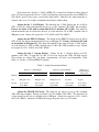
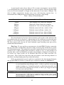
Table 1. Alarm Concentration Limits
Alarms for % GAS Display
Alarms for ppm CO Display
Methane
ON
1% or less
OFF
No alarm
ON
1% or less
OFF
1% or less
Alarms for %
Oxygen Display
Always ON
0.5% (10% LEL)
CO
200 ppm or less
200 ppm or less
200 ppm or less
No alarm
35 ppm
Oxygen
19.5% LoO2
23.0% HiO2
19.5% LoO2
23.0% HiO2
19.5% LoO2
23.0% HiO2
19.5% LoO2
23.0% HiO2
19.5% LoO2
23.0% HiO2
Alarms for TRACK GAS Scale. The alarm for gas may be set up to 1.0% methane
(20% LEL) but no higher. Factory set alarm is at 1.0% methane (20% LEL). The alarm for CO
is that selected by the user or a default value of 200 ppm. Alarms for oxygen are 19.5% (LoO2)
and 23.0% (HiO2). Alarms for CO/H2S and oxygen are given once very 15 seconds.
7
4.
ENCLOSED SPACES, LEAK DETECTION, BAR HOLING, AMBIENT AIR AND
FLUE GAS TESTING FOR CO
A
Test and Monitor an Enclosed Space Atmosphere
The CGA-411 and CGA-412 detectors may be used to test and to monitor an enclosed
space atmosphere.
WARNING:
The detectors respond to natural gas (methane), carbon monoxide,
hydrogen sulfide, and oxygen. These detectors cannot be relied upon for
testing or monitoring other gases.
To Test an Enclosed Space Atmosphere. Connect an appropriate probe to the detector,
turn the instrument on by switching to the % Oxygen display, and allow it to warm up. Do not
use any filter other than a dust and water-block filter (the filter attached to the coiled hose). After
warm-up, insert or lower the probe into the space to be tested. Wait for at least 45 seconds to
make sure that all sensors have reached full response. If there is no alarm, check the readings on
the PPM CO and % GAS displays. If an alarm does sound, switch to the display whose symbol
appeared and verify the gas level causing the alarm condition. Do not enter an enclosed space if
an alarm for any gas is given.
To Monitor an Enclosed Space. To monitor an enclosed space for the gases detected by
the CGA-411 and CGA-412, first proceed as above to test the space atmosphere and then
continue to monitor using the % Oxygen scale. If an alarm is given, exit the space and then
verify the gas and its concentration by switching to the appropriate display. Alarm levels and
their visual symbols are:
Table 2. Alarms for % Oxygen Display
% Oxygen Display
Alarm Limit
Display Symbol
Gas
Methane
0.5% (10% LEL)
GAS
Carbon Monoxide
35 ppm
CO
Hydrogen Sulfide
9 ppm
CO
Oxygen
Less than 19.5%
LoO2
More than 23.0%
HiO2
WARNING:
A detector should always be warmed-up in ambient air, never in an
enclosed space atmosphere.
8
B.
Leak Detection
The TRACK GAS scale may be used to test for gas leaks and to locate their source. To
use this feature, connect an appropriate probe and turn the selector switch to the TRACK GAS
position. The display will show "Snif" (sniff) for about 10 seconds. After this initial warm-up,
the display shows the concentration of methane (natural gas) in air in % LEL (Model CGA-411)
or in % GAS (Model CGA-412). If ambient air is clean (contains no methane), the display
should read zero. If it does not, use the AUTO ZERO to adjust the instrument zero.
To locate a leak, advance the probe along a pipe or other conduit at a rate of about one
foot per second. Since methane is lighter than air, track a gas pipe from above wherever
possible. The beeper will sound once every two seconds at ambient concentrations of natural
gas, will speed up with rising concentration, and will beep continuously at 2% LEL (or 0.1% gas)
above ambient. By listening to the beeper or by reading the display, the source of the gas leak
can be located.
The TRACK GAS scale displays readings in increments of 0.2% LEL (CGA-411) or
0.01% GAS (CGA-412). The ambient gas concentration used to establish the lowest beep
frequency is automatically reset every time the TRACK GAS scale is selected.
The instrument response time depends on the length of the probe attached to the detector.
To shorten the response time (to about half a second) use a gooseneck probe and filter (see
Section 9). A gooseneck probe is also convenient for one-hand operation of the detector.
C.
Bar Holing
The CGA-411 and CGA-412 may be used to measure gas levels in sampling holes used
for locating underground natural gas resulting from seepage or a leak in a conduit. Gas
concentrations in a bar hole near a significant leak will be several percent. Therefore, an alarm
for gas is likely, but it has no relevance to the ambient atmosphere above ground. Under these
conditions, the alarm for the % GAS display may be set to OFF (see Section 11). The % GAS
display is now a measuring scale. Alarms for CO and low or high oxygen will still be given, but
at a reduced frequency (once every fifteen seconds) so as not to interfere with the display of gas
concentrations.
Bar holing may be done with optional probes available from Bascom-Turner. These
include a 36" long plastic probe, a fiberglass probe, and a steel probe with an electrically
insulated handle (see Section 9). An optional accessory, the Water-stopper, may be used to
minimize interruptions from accidental aspiration of ground water (see Accessories).
D.
Ambient and Flue Gas Testing for Carbon Monoxide
Ambient Air. The PPM CO display is used for measurements of carbon monoxide in
ambient air. Accessible concentrations are 1 ppm to 9999 ppm. Readings above 1000 ppm are
precise to about ±10%.
9
A general guide on the adverse effects of CO at various concentrations is given in Table
3. A concentration above 35 ppm in breathable air is cause for concern. The time-weighted limit
(8 hr.) for CO in the workplace is 50 ppm and the short-term (15 min.) limit is 200 ppm. The
effect of higher concentrations becomes more severe with increasing exposure time. A
concentration above 200 ppm may be life-threatening, if exposure is long enough.
Table 3. Effects of Carbon Monoxide
Concentration
Inhalation Time and Symptoms
50 ppm
Time-weighted (8 hr.) limit in the workplace
200 ppm
Short-term (15 min.) limit in the workplace
400 ppm
Headache in 1-2 hrs., life threatening after 3 hrs.
800 ppm
Headache, nausea in 45 min., death in 2-3 hrs.
1,600 ppm
Headache, nausea in 20 min., death in 1 hr.
3,200 ppm
Headache, nausea in 5 min., death in 30 min.
6,400 ppm
Headache, nausea in 1 min., death in 10 min.
The electrochemical cell used for CO measurements will respond to other substances that
are oxidized by the cell (see Section 5). Measurements of CO in ambient air can be made more
specific to CO by using the filter and probe provided for flue-gas measurements (see below).
The filter removes most, but not all, easily oxidizable vapors including some given off by
common household chemicals.
Flue Gases. To carry out flue gas measurements, select the PPM CO display, connect the
flue gas probe with its attached filter, and after warmup, insert the probe into the flue to read the
CO concentration in ppm. The standard flue gas probe is intended for flue gas checks which last
a minute or two. Longer sampling times may lead to a display of "bloc" as water condenses in
the probe, filter, or hose and blocks the gas intake to the instrument. If checks for CO in flue gas
are needed over longer periods use an Extended Duty Flue Gas Probe and Filter (see
Accessories). These probes have larger heat sinks and contain a water-removing substance in
their filters extending sampling times up to about half-an-hour.
If flue gas measurements are to be made on a regular basis, the alarm for the CO display
may be turned OFF (See Section 11) if the flue gas is expected to contain over 200 PPM CO.
CAUTION:
When measuring CO in flue gas, the filter provided with the probe must be used
to avoid interference from nitrogen oxides. A filter is good for at least three
months of ordinary use. It should be replaced or refilled when about 90% of its
purple materials has changed color to brown, or when it gets clogged or flooded
(see Accessories and Spare Parts).
WARNING:
Do not touch the flue probe immediately after a measurement. Running
the instrument for a short time in ambient air helps cool the probe quickly
and also removes condensed water.
10
"Air-free" CO Flue Measurements. Flue gas measurements of CO can be displayed on
an "air-free" basis if this feature is selected (see Section 11). When this selection is made, the
measured CO concentration is referred to air-free flue gas according to:
"Air-free" PPM CO
=
20.9
(measured ppm CO)
20.9 − measured % O2
The instrument measures CO and % Oxygen and displays CO concentrations on an air-free basis
using the above relation. This calculation is used up to 16.0% Oxygen. If the oxygen
concentration is above 16.0%, measured values are displayed without conversion, i.e., the "airfree" formula is not used.
E.
Hydrogen Sulfide Detection
The electrochemical cell used to detect CO also responds quantitatively to hydrogen
sulfide (H2S). The response to 1 ppm H2S is registered as 4 on the PPM CO display. This ratio
holds for all values of H2S up to about 1000 ppm H2S. Thus, 10 ppm H2S will register as 40 on
the PPM CO display, 50 ppm H2S will register as 200 on the PPM CO display and 100 ppm H2S
will register as 400 on the PPM CO display. The CGA-411 and CGA-412 detectors thus monitor
ambient levels of hydrogen sulfide, as well as CO, and will alarm if the H2S concentration rises
above one quarter of the limit set for the CO alarm. In particular, when the % Oxygen display is
selected, a detector will alarm at 9 ppm H2S (approximately one quarter of the 35 ppm alarm
limit for CO).
The response of the electrochemical cell to H2S is automatically calibrated whenever the
unit is calibrated with CO. No separate calibration with H2S is required.
If an atmosphere contains both CO and H2S, the response of the detector is additive, that
is, the reading on the PPM CO display includes both the response to CO and to H2S. If a reading
for CO only is needed or desired, the flue gas probe and its attached filter can be used for
sampling ambient air. The filter removes H2S and the reading then corresponds to the CO
concentration.
WARNING:
A detector will not respond to H2S when the sampled gas is drawn through
the flue gas probe and filter.
11
5.
INTERFERENCE FROM OTHER GASES OR LIQUIDS
Methane detection uses a catalytic combustion filament and a thermal conductivity
sensor, both calibrated with methane. The filament is used up to about the lower flammable limit
(5.0% by volume) of methane and the thermal conductivity sensor from about 5% to 100% of
methane.
Carbon monoxide (CO) and hydrogen sulfide (H2S) detection is carried out with a threeelectrode, electrochemical cell. Oxygen detection is carried out electrochemically with a twoelectrode, diffusion membrane electrochemical cell.
Gases, or liquids with appreciable vapor pressure, which may interfere with the detection
of methane include substances which can be combusted on the catalytic combustion filament.
Examples are ethane, propane, ethylene, propylene, octane, and the like. Also, substances which
differ in thermal conductivity from air. Examples are hydrogen, helium, carbon dioxide, other
hydrocarbons.
Gases or vapors which may interfere with carbon monoxide detection include substances
which can be electrochemically oxidized or reduced on the working electrode of the
electrochemical sensor. Examples are hydrogen, oxides of nitrogen, alcohols, and unsaturated
hydrocarbons.
Interference in CO Measurements
If the ambient concentration of oxidizable substances is relatively high, it is likely that
CO measurements will be affected. Many of these substances are removed by the flue gas filter
attached to the telescoping metal probe. This filter can be used for both flue gas measurements
and for ambient air measurements of CO whenever the ambient concentration of other oxidizable
substances is significant.
CAUTION:
DO NOT attach the flue gas filter to the standard probe. It is designed to be
used only with the CO probe (flue probe).
Catalyst Poisons
WARNING:
Both the methane sensor and the CO sensor use catalytically active surfaces
which may be poisoned by air contaminants. These sensors should not be
exposed to atmospheres that contain silicones, halogens and halides, such as
chlorides, and volatile compounds containing lead or antimony. If
exposure to atmospheres that adversely affect the sensors is suspected, the
detector should be recalibrated promptly.
12
6.
INSTRUMENT CHECKS
Pump Checks
If the intake is blocked, the display shows "bloc" (block) and the detector beeps until the
problem is cleared. This check is carried out whether or not a probe is being used. To check for
tight connections, block the probe inlet to sow "bloc" on the display within a few seconds. If
"bloc" fails to appear, there may be a leak (see "Troubleshooting").
WARNING:
The instrument should not be used if it doesn't display "bloc" when the
intake is blocked.
Automatic Zero
To adjust the zero automatically, advance the selector switch to "AUTO ZERO". Zero
adjustment, which takes 25 to 35 seconds, is typically required only once a day.
Display
Air (O2)
GAS 1
CO
GAS 2
End
Automatic Operation
The oxygen sensor is adjusted to 20.9%.
The zero of the thermal conductivity sensor is adjusted.
The zero of the CO/H2S sensor is adjusted.
The zero of the combustion sensor is adjusted.
The instrument beeps briefly after it has been zeroed and is ready to use.
If automatic adjustment of zero cannot be carried out, for example, because the methane
concentration is too high, or because a sensor has drifted too far from its previous null (zero), the
display will show "nogo" (no go) alternating with the symbol of the gas indicating which sensor
cannot be adjusted.
If an automatic zero attempt leads to "nogo", subsequent selection of some display mode
(% GAS, PPM CO, or % Oxygen) will display "nogo" alternating with the symbol for the
display. The instrument must then be zeroed as described below.
WARNING:
Zero adjustment must be carried out with clean air. If the air is not clean,
a systematic error will be introduced. The instrument will auto zero if
methane is below 0.5% and CO below 35 ppm. At higher concentrations of
methane or CO, the instrument will not change its zero, and the display will
show "nogo" (no go).
13
Coarse Zero
To adjust the zero of a sensor which has drifted too far, remove the instrument from its
carryall, and remove the elongated rubber plug on the right side of the instrument (as you face it)
to access two push-button switches. Place the instrument on a flat surface and set the selector
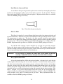
switch at the % oxygen display. Hold down push-button #1 (see Figure 1) with a pencil, pen, or
other small implement while switching the selector switch to AUTO ZERO. Release button
when zeroing begins. The instrument will proceed to zero all sensors.
Please note that the round rubber plugs to the right of the elongated plug need not be
removed. Please be sure to replace the elongated plug before re-inserting the instrument into the
carryall.
WARNING:
The coarse zero procedure overrides the limits for autozeroing.
procedure must be carried out in clean air.
This
Automatic Sensor Check
If a gas sensor fails (opens up), the display shows "FAIL" (see Troubleshooting Section).
Fig. 1.
Radio Frequency Interference (RFI)
Gas-Sentry detectors have an interior coating on their cases to suppress RFI.
14
7.
CHANGE OF BATTERIES
Automatic Battery Check
The Gas-Sentry CGA-411 and CGA-412 can be powered by four (4) alkaline (nonrechargeable) AA batteries (1.5V, Type AM-3) or by four (4) Ni/Cd rechargeable batteries
(1.25V, 0.85 Ah). If the estimated battery life is less than about 1 hour, the display flashes "Lo"
(low) between readings. The batteries should be changed at a convenient time. If the battery life
is over, the display stays on "Lo". The batteries must then be changed to make the instrument
operational.
WARNING:
The batteries must be changed in an atmosphere known to be
non-hazardous.
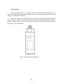
To replace batteries:
1.
Remove batteries
Snap open the bottom part of the carryall, partially
withdraw the instrument, and slide out the battery
cover by depressing latch with thumb while pressing
down on cover with fingers.
2.
Discard four alkaline AA cells or remove four Ni/Cd cells.
Fig. 2.
Insert four, fresh AA alkaline batteries or recharged Ni/Cd batteries. Insert each battery
with the correct polarity as shown on rear of instrument. Replace battery cover and lock
into place. Always replace a set of batteries, do not mix new and used batteries.
If the instrument does not operate after battery replacement, or if the display is dim, there is
a high probability that one or more cells have been inserted with the wrong polarity. Re-insert
the batteries taking extra care to insert each battery correctly.
Note: The CO cell is powered by the four batteries in the unit even when the instrument is OFF.
The instrument should not be left without power for more than one minute during battery
replacement. If the instrument is without batteries for an extended period, the CO cell
will require about 10 minutes to return to a proper operating condition.
CAUTION:
Always store the instrument with a full complement of batteries.
WARNING:
Use only alkaline or Ni/Cd batteries in a Gas-Sentry. Do not attemp to
charge the alkaline (non-rechargeable) batteries as they may leak or vent.
15
8.
TROUBLESHOOTING
Problem
Probable Cause
Action
1. Display is blank and pump
does not operate.
• Batteries are too low or
spent.
• Replace
batteries
(see
Section 7 ("Change of
Batteries").
2. Batteries are replaced but
display is blank and pump
does not run.
• One or more batteries were
inserted with the wrong
polarity.
• One or more batteries are
too low.
• Re-insert batteries
proper polarity.
3. The Display shows "bloc".
• The intake to the instrument
is blocked.
• There is water in the probe.
with
• Replace batteries with a
new set.
• Check probe tip and waterblock and inlet filters, and
clean
or
replace
if
necessary.
• Detach probe from waterblock and inlet filters, and
dry probe and filter by
shaking.
4. The display does not show
"bloc" when the probe tip
is blocked.
• There is a leak between the
probe tip and the pump.
• Tighten connections of
probe. Check hose and
probe for cracks.
• Disconnect hose and block
intake. If "bloc" does not
appear, clean pump.
5. The display shows "nogo"
prior to "End" when on
AUTO ZERO scale.
• Ambient concentration of
methane or CO is too high.
• Repeat zero in clean air. If
necessary, leave instrument
on in clean air to purge.
• Check pump by blocking
probe's tip.
If "bloc"
appears repeat zero in clean
air following "coarse zero"
procedure in Section 6.
• Replace sensor.
• Detector will not purge on
LEL or GAS scale.
• The CO sensor has failed.
6. The display shows "FAIL".
• The gas or the oxygen
sensor has failed.
• Replace sensor.
WARNING: Do not open a sensor under any conditions. Sensors must be replaced only
by personnel trained in instrument service.
WARNING: Do not operate an instrument which fails to show "bloc" when the intake is
blocked. Clean the pump or return the instrument for repair. See the
inside of the front cover (limited warranty) on how to return an instrument.
16
9.
PROBES AND FILTERS
Standard Probe
The standard probe (Part No. SP-207) is a rigid tube which connects to the water-block
filter. If extra length is desired, an extension (7") is screwed finger-tight onto the end of the
probe. A rubber gas collector (Part No. RT-107) on the end of the extension is useful for finding
leaks under windy conditions.
WARNING:
Do not use this probe for flue gas measurements. The plastic probe will
become soft, deform, or decompose.
Flue Gas Probe
The flue gas probe (Part No. FP-110) is a telescoping metal probe screwed finger-tight
into the flue gas filter cartridge. The other end of the filter cartridge attaches to the water-block
filter. This probe, together with its filter cartridge, is recommended for CO measurements in flue
gas and ambient air.
WARNING:
Never attach the filter cartridge directly to the sample hose - always use a
water block filter.
WARNING:
Hold the probe without touching the metal while it is in the flue and
immediately afterwards.
Running the instrument in air after a
measurement will help cool the probe and dry the filters.
Gooseneck Probe
The optional gooseneck probe (Part No. GP-014) is 14" long and attaches directly to the
inlet port of the detector. The short length and low internal volume of this probe reduces the
time required to pull a gas sample from the probe tip to the gas sensors. This probe optimizes the
response time on the TRACK GAS scale. To increase sensitivity in windy conditions, use a
rubber gas collecting tip (Part No. RT-107) on the end of the probe.
Bar Hole Probes
There are four optional probes suitable for bar holing:
Bar Hole/Ceiling Probe (Part No. BP-034) 34" long, clear, one hole at end.
Bar Hole Probe (Part No. BP-134) 34" long, clear, side holes.
Bar Hole Probe (Part No. BP-436) 36" long, fiberglass, one hole at end.
Bar Hole Probe (Part No. BP-536) 36" long, steel, side holes.
The bar hole/ceiling probe has a single inlet on the end and comes with a rubber gas collector
(Part No. RT-030) useful for finding leaks in overhead pipes. The stainless steel probe has an
17
electrically insulated handle. Bar hole probes are designed to be attached to the water block
filter on the coiled hose. A more convenient hose for bar hole measurements, five feet of
straight tubing, is available as Part No. SH-060.
CAUTION:
Hold the steel bar hole probe only by the insulated handle to avoid electrical
shock from buried power lines.
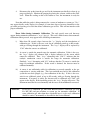
Dust and Water-block Filter
A Teflon filter removes particles of dust and dirt and blocks water. The white disk in
the filter should be inspected periodically for accumulated dirt which may slow air sampling. A
filter can be cleaned by removing the probe and tapping the filter on a hard surface to remove dry
dust and dirt. Do not insert objects into the water block filter while attempting to clean it as they
may puncture the Teflon. Typically, the filter needs to be replaced once or twice a year.
Replacement water-block filters are available as Part No. WF-305 (package of 5 filters).
Fig. 3. Dust and water-block filter.
Inlet Dust Filter
Removal of the intake connector (used to attach the sampling hose) exposes a metal filter
cup pressfit onto the intake. These filters are not a substitute for water-block filters since they
will not block water. If this filter gets blocked, it may be cleaned with compressed air or
replaced.
Water-block Filter for Gooseneck Probe
A Teflon filter, housed in a knurled nut, removes particles of dust and dirt and blocks
water (see the Dust & Water-block Filter section above for details on cleaning). Replacement
filters are available as Part No. WF-205 (package of 5 filters).
Fig. 4. Water-block filter for gooseneck probe.
WARNING:
Do not use a Gas-Sentry without a dust and water-block filter. Do not use
a dust and water-block filter with a puncture in the Teflon disk.
18
Dust Filter for Gooseneck Probe
A dust filter in the tip of the gooseneck probe can be cleaned by removing the probe from
the detector and tapping the probe's tip on a hard surface to remove dry dust and dirt. The dust
filter can be popped off the end of the probe and replaced. Replacement dust filters are available
as Part No. DF-005 (package of 5 filters).
Fig. 5. Dust filter for gooseneck probe.
Flue Gas Filter
This filter is designed to be screwed finger-tight between the telescoping metal probe and
the water-block filter. It must be used for CO measurements in flue gas and may also be used for
CO measurements in ambient air. The beads in the filter cartridge should be replaced when
about 90% of the material has changed color from purple to brown or when it becomes blocked
by soot or water. Filter beads for refilling approximately 50 cartridges are available as Part No.
PR-050. Replacement flue gas filters are available as Part No. FF-005 (package of 5 filters).
To refill the filter cartridge, remove threaded top and pour out spent filter material.
Retrieve the plastic retainer disk from the spent filter material. Fill cartridge with fresh filter
material to bottom of threads and place the plastic retainer disk flat on top of the filter material.
Screw in top until finger tight and check seal with block test.
WARNING:
Do not remove or puncture the white filter in the bottom of the filter
cartridge. If this filter becomes damaged, discard the filter cartridge.
Heavy Hydrocarbon Filter
A heavy hydrocarbon filter, filled with activated carbon, is designed to be used with the
standard probe or the bar hole probe on a one-time-only basis. Activated carbon adsorbs gasoline
and other heavy hydrocarbons (for example, propane or butane) which interfere with methane
detection. In order to keep the filter material from adsorbing hydrocarbons prior to use, the filter
is fitted with plastic endcaps which must be removed just before use. The filter should be either
discarded after use or refilled with activated carbon and recapped with the plastic endcaps. This
filter is designed to be screwed finger-tight between the probe and the water-block filter.
Activated carbon for refilling approximately 50 cartridges is available as Part No. HR-050. The
refill procedure is the same as described for the gas filter. Heavy hydrocarbon filters are
available as Part No. HF-005 (package of 5 filters).
19
Water-stopper
The water-stopper (Fig. 6) is a floating check-valve, with push-button water release, to
stop water from being pumped while bar-holing. It provides a quick way to continue bar-holing
if water is encountered in a bar-hole.
The water stopper is inserted between the water-block and dust filter and the bar-hole
probe. The float inside the water-stopper is connected to a plunger which blocks flow whenever
the float is lifted by water. Water is released and the plunger is returned to its normal position by
depressing a release push-button.
Fig. 6. Water stopper for bar-holing.
20
PART 2. CALIBRATION AND ALARM LEVEL SELECTION
10.
AUTOMATIC CALIBRATION WITH A-CAL
The A-CAL firmware calibrates instruments automatically using calibration gas available
from Bascom-Turner
Calibration Gas. The gas required for automatic calibration of the catalytic combustion
and CO sensors is Bascom-Turner's methane and CO calibration gas (Part No. MC-105)
containing 2.5±0.05% methane and 100 ppm ±2 ppm CO in air. It is provided in a disposable
aluminum tank containing 105 liters of gas, sufficient for at least 300 calibrations.
The thermal conductivity sensor can be calibrated with either pure methane or system gas
provided by the user.
The oxygen sensor is calibrated with ambient air whenever the instrument is autozeroed.
Calibration Gas Dispenser. The calibration gas must be delivered at or near
atmospheric pressure to ensure accurate calibration. Bascom-Turner recommends using the
Calibration Gas Dispenser (Part No. CGD-001) which regulates and displays the delivery
pressure, approximately 6-7 inches of water.
A-CAL Operation. In carrying out automatic calibrations with the A-CAL firmware,
always calibrate the catalytic combustion and CO sensors first, that is, use the BascomTurner methane and CO calibration gas first. Then, if necessary, recalibrate the thermal
conductivity sensor. This sequence of calibration gases ensures that no errors are introduced
from residual gas in the detector.
A-CAL Calibration with the Methane and CO Calibration Gas
1.
Place the selector switch in "AUTO ZERO" and zero the instrument in clean air.
The usual series of displays will appear on the detector display, depending on the
model.
2.
After "End" appears on the display and the instrument beeps, insert the tip of the
standard probe partially into the outlet port of the gas dispenser. If a manual
calibration apparatus (for example, Part No. PCA-001) is used, attach the detector's
water-block filter to the threaded hose bar (TB-512) with the regulator's valve off
and wait for "bloc".
3.
After "bloc" appears on the detector display, push the probe completely into the
dispenser port. The "bloc" display will be replaced by "go" and the instrument will
proceed to calibrate the catalytic combustion and CO sensors.
If a manual apparatus is used, open the regulator's valve and observe "go" on the
display.
21
4.
The detector display will show "GAS 2" while the catalytic combustion sensor is
being re-calibrated and "CO" when the CO sensor is being re-calibrated.
5.
After calibration, the detector will show "CAL" and the instrument will beep briefly.
Remove the probe from the gas outlet. The instrument is ready for use.
Note: When the Gas Dispenser is used, it may be useful to attach the 7" extension (with the
white Teflon tip) to the end of the standard probe. The white Teflon tip is designed to fit
the Gas Dispenser port.
Note: During calibration, the selector switch remains in the AUTO ZERO position. After
calibration is complete and "CAL" is displayed, the selector switch must be placed at
some other scale (or the OFF position) to return the detector to a normal operating mode.
CAUTION:
Automatic calibration presupposes and depends on using Bascom-Turner's
calibration gas (Part No. MC-105). Do not use a different gas for automatic
calibration.
A-CAL Calibration with the Methane or System Gas
The thermal conductivity sensor is calibrated at the factory with methane. Routine recalibration of this sensor is not necessary. The thermal conductivity sensor is checked
operationally using air as the reference gas every time the AUTO ZERO routine is used.
However, the thermal conductivity sensor should be re-calibrated if it has been re-calibrated by
the user with system gas since the gas composition varies seasonally and sometimes more
frequently.
To calibrate the thermal conductivity sensor, proceed as follows:
1.
Place the selector switch on "AUTO ZERO" and zero the instrument in clean air.
The usual series of displays will appear on the detector display. Note that if the
instrument had just been calibrated with the methane and CO calibration gas, the
selector switch must be moved to some other scale and given 30 seconds to purge
residual gas before the AUTO ZERO routine is repeated.
2.
After "End" appears on the display and the instrument beeps, block the probe tip
manually until "bloc" appears on the display. Now release the block. The display
will show "go" and the instrument is ready for calibration.
3.
Connect the probe to a source of pure methane or system gas. The gas should not
exceed 6" or 7" of water. The display will show "GAS 1" while the thermal
conductivity sensor is being calibrated. When calibration is complete, "CAL" will
appear on the display and the instrument will beep briefly.
22
4.
Disconnect the probe from the gas and let the instrument run briefly in clean air to
purge residual gas. Monitor the purging by placing the selector switch on the GAS
scale. When the reading on this scale returns to zero, the instrument is ready for
use.
Note that while the probe is being connected to a source of methane or system gas, "bloc"
may appear briefly on the display, for example, if some time elapses between connection to the
gas outlet and opening of a valve that allows calibration gas to flow. This will not interfere with
proper calibration.
Error Codes during Automatic Calibration. The only special error code that may
appear during automatic calibration is "nogo" (no go). This code, which denotes that automatic
calibration cannot proceed, may appear in the following circumstances:
i).
More than 30 seconds elapse between the "go" display and the introduction of
calibration gas. If this is the case, wait for an additional period up to 60 seconds,
with gas flowing through the instrument. The "nogo" display will be replaced by
"CAL" when the sensors are calibrated.
ii)
A sensor is outside the normal range for automatic calibration. If this is the case,
the "nogo" display will alternate with a display indicative of the sensor which
cannot be calibrated. Thus, "nogo" alternating with "GAS 2" indicates that the
catalytic combustion sensor is outside the range for automatic calibration.
Similarly, "nogo" alternating with "CO" indicates that the CO sensor is outside the
range for automatic calibration. If this result is obtained, the detector must be
calibrated manually.
iii)
A sensor is not sufficiently stable for calibration to proceed normally or the gas
composition is varying with time. This last condition may hold if the calibration
system has not been purged (e.g., first calibration of the day). If this is the case,
wait for an additional period of up to 60 seconds with gas flowing through the
instrument. If response is stable, the detector will be calibrated and "CAL" will
appear on the display. If the instability persists, the "nogo" display will persist. The
instrument must then be tested manually and the cause of the malfunction corrected.
CAUTION:
Do not use a calibration gas other than Bascom-Turner's calibration gas (Part
No. MC-105) and pure methane or system gas for automatic calibration. If
some calibration gas other than those stipulated here is to be used, calibration
should be carried out manually as described in the Service Manual.
23
11.
ALARM LEVEL SELECTION. "AIR-FREE" CO OPTION SELECTION
The instrument has an alarm activated at preset levels. Factory set alarm limits are given
in Section 3C. The TRACK GAS scale has both an alarm and a beeper which may be disabled
without disabling the alarm.
To review or change alarm limits, remove the instrument from its carryall and take out
the elongated rubber plug on the side of the instrument. Two push button switches, labeled #1
and #2 in Figure 7, will be exposed. Set the front panel selector switch to AUTO ZERO and
after "Air" is displayed, press switch #2. The pump will stop running and the instrument will
enter a display/set-up mode for alarms and other options.
Fig. 7.
To Display Alarm Levels Without Changing Them. Each time switch #2 is pressed,
the display advances through the sequence shown in Table 4. The display shows whether an
alarm or other option is ON or OFF, and if ON, at what level.
To Turn Off or On Alarms or Select Options. Alarm levels for gas and CO/H2S can
be adjusted within certain limits or turned OFF, the beeper for the TRACK GAS scale may be
turned OFF, the CO display may be put on an air-free basis, and the block limit for the pump may
be adjusted by using switches #1 and #2. The oxygen alarm limits are always ON at the factory
set levels.
To turn an alarm OFF or select an option, enter the alarm display mode as described
above (set selector switch to AUTO ZERO and press switch #2 once), advance to the relevant
display by pressing switch #2 an appropriate number of times, and then press switch #1. Each
time switch #1 is pressed, the display changes from OFF to ON (and the reverse). If the change
to be made is to turn off a particular alarm or operating mode, once OFF appears on the display,
press switch #2. The display will show a symbol followed by OFF (see Table 4). Exit by turning
the selector switch out of the AUTO ZERO position or continue, by pressing switch #2, to a
subsequent display of another alarm or option to be changed.
The oxygen alarms and the block level for the pump cannot be turned OFF. If OFF is
entered with switch #1, when switch #2 is pressed, the display will show "LoO2" or "HiO2" or
"Pu" followed by a number (19.5 for LoO2, 23.0 for HiO2 and the block limit for the pump).
24
Table 4. Display Sequence
Display
Statement
bEEP followed by ON
Use/Comments
or by OFF
The TRACK GAS beeper is active.
The TRACK GAS beeper is silent.
Used only for turning beeper ON or OFF. The alarm
limit is set by SniF display (see below).
or by OFF
The TRACK GAS alarm is at value shown.
The TRACK GAS alarm is OFF.
If ON, displayed number is % LEL (CGA-411) or
% GAS (CGA-412). Maximum setting is 20% LEL
or 1.00% GAS.
or by OFF
The % GAS display alarm is at value shown.
The % GAS display alarm is OFF.
If ON, displayed number is % GAS. Maximum
setting is 1.00% gas.
AFCO followed by a number
or by OFF
The air-free CO option is enabled.
The air-free CO option is disabled.
Used only for enabling or disabling air-free CO
option.
CO followed by a number
The PPM CO display alarm is at value shown.
The PPM CO display alarm is OFF.
If ON, displayed number is PPM CO. Maximum
setting is 200 PPM CO.
LoO2 followed by a number
The lower alarm limit for oxygen is at value
shown.
This alarm is always ON. Lower limit may not be set
less than 19.5% oxygen.
HiO2 followed by a number
The upper alarm limit for oxygen is at value
shown.
This alarm is always ON. Upper limit may not be set
higher than 23.0% oxygen.
Pu followed by a number
The block limit for the pump is at value shown.
Factory set number is 2500. Can be changed to adjust
the pump (see Section 12E).
Air
The instrument reverts to the normal operating
mode at AUTO ZERO.
Exit from set-up mode to AUTO ZERO (alternatively,
exit by placing selector switch at a position other than
AUTO ZERO).
SniF followed by a number
GAS followed by a number
or by OFF
25
To Change Alarm Levels. If an alarm level is to be changed, rather than turned OFF,
select the relevant display by pressing switch #2 an appropriate number of times, then press
switch #1 until ON appears, then press switch #2. The display will show a number (the previous
alarm level) with a flashing first digit. If this digit does not need to be changed, press switch #2
again. The next digit will now be flashing. To change the digit, press switch #1 to advance
sequentially through 1,2,3,...0. Once the proper digit is reached, press switch #2 to advance the
flashing digit to the next position. Repeat until all digits are adjusted. At the end, the display
will show the relevant symbol followed by the new alarm level.
Examples of Selection or Adjustments
To Disable the Beeper on the TRACK GAS Scale. Set selector switch to AUTO
ZERO and press switch #2.
Press
Display
BEEP
Switch #1
OFF
Switch #2
BEEP
Followed By
ON
OFF
Exit by placing the front panel switch to a position other than AUTO ZERO. The
beeper on the TRACK GAS scale can be activated again by repeating the above procedure.
To Change the Alarm Level for the % GAS Display to 0.5% Gas. Set the front panel
selector switch to AUTO ZERO and press switch #2 three times. The display will advance to
GAS followed by a number (the current alarm limit). Continue by
Press
Switch #1
Switch #2
Switch #2
Switch #1
Switch #2
Switch #1
Switch #2
Switch #2
Display
Comment
ON
01.00
01.00
Underlined digit is flashing
Underlined digit is flashing
Continue pressing switch #1 until
0 appears as the second digit
00.00
00.00
00.50
00.50
GAS followed by 0.50
Continue pressing switch #1 until
5 appears as the third digit
Exit by placing the front panel switch to a position other than AUTO ZERO.
26
To Change the Alarm Level for the CO Display to 35 PPM CO. Set the front panel
switch to AUTO ZERO and press switch #2 five times. The display will advance to CO
followed by a number (the current alarm level). Continue by
Press
Switch #1
Switch #2
Switch #2
Switch #1
Switch #2
Switch #1
Switch #2
Switch #1
Switch #2
Display
Comment
ON
0200
0200
Underlined digit is flashing
Underlined digit is flashing
Continue pressing switch #1 until
0 appears at the second digit
0000
0000
Continue pressing switch #1 until
3 appears as the third digit
0030
0030
Continue pressing switch #1 until
5 appears on the last digit
0035
CO followed by 35
Exit by placing the front panel switch to a position other than AUTO ZERO.
27
12.
MANUAL CALIBRATION, SENSOR REPLACEMENT, PUMP ADJUSTMENT
Manual calibration is required if a sensor has drifted too far to be calibrated automatically
and sometimes when a sensor is replaced. Since the procedures described below accesses basic
operating parameters, safeguards have been built to ensure that the set-up mode is not entered
accidentally.
To access the set-up mode, remove the instrument from its carryall and take out the
elongated rubber plug on its side. Place the instrument on a flat surface with some stop to keep
the instrument in place. Set the front panel switch to the % Oxygen position and press both
switches #1 and #2 (see Figure 7) simultaneously with a small implement wide enough to reach
both switches. While switches #1 and #2 are depressed, turn the frontpanel switch from the
% Oxygen position to AUTO ZERO. The instrument will enter the set-up mode for manual
calibration and adjustment; the display will show "Pu" (pump).
The parameters that can be accessed in the set-up mode are described in Table 5. Each
state is reached sequentially by pressing switch #2 and can be adjusted by using switches #1 and
#2 in the same way as described in detail for setting alarm levels (see Section 11). Ordinarily,
only some of the parameters need be adjusted during manual calibration or when installing a new
sensor. The main adjustments to an instrument in the field are described separately below.
A.
Manual Calibration
If the sensitivity of a sensor has drifted too far to be automatically adjusted, "no go" will
appear during autocalibration. The sensor must then be calibrated manually.
To calibrate, enter the set-up mode (see above) and press switch #2 until GAS 2 appears
on the display (4 depressions). If clean air is being pumped through the instrument, the display
should show 0.00 or -0.00. Introduce calibration gas (2.5% methane) and adjust the display by
using switch #1 and switch #2, as described in Section 11 and in the example below, until the
display reads 2.50.
Example: The display reads 1.45 with calibration gas. To adjust, press switch #1. The
display will flash the left most digit, a zero. Press switch #2. The display will now flash the
second digit, 1. Press switch #1 to advance to 2; press switch #2. The third digit, 4, will now be
flashing. Press switch #1 to advance the third digit to 5. Press switch #2; the last digit, 5, will
now be flashing. Press switch #1 until this digit is zero, and then press switch #2. The display
will show "GAS 2" followed by a number which ought to be 2.50. If this number is more than
2.52 or less than 2.48, repeat the procedure (beginning with switch #1) to adjust again to 2.50.
The procedure for calibrating manually the CO sensor is similar. After entering the setup mode, switch #2 is pressed until "CO" appears on the display followed by a number (7
depressions). The number is adjusted to 100 (assuming the calibration gas contains 100 ppm
CO) by using switches #1 and #2 as described in Section 11.
28
Table 5. Display Sequence in Set-Up Mode
Display*
Parameter
Use/Comments
Pu
followed by a number
Pump current in arbitrary units
Used to adjust block limit for pump (see Section 12E)
bA
followed by a number
Battery voltage
Should be between 2.15 and 3.15 (Do NOT Adjust)
o
followed by a number
Room temperature (oC)
For installing a new sensor (Sect.12B)
o
followed by a number
Filament temperature (oC)
For installing a new sensor (see Sect. 12B)
GAS 2 followed by a number
In Calibration Gas: % GAS
For manual calibration or installing a new sensor (Sects. 12A
and 12B)
GAS 1 followed by a number
In Pure Methane: % GAS
For manual calibration or installing a new sensor (Sects. 12A
and 12C)
o
followed by a number
Room temperature (oC) of the on-board
temperature sensor
Should read room temperature (oC) (Do NOT Change)
CO
followed by a number
In Calibration Gas: PPM CO
For manual calibration or installing a new CO/H2S Cell
(Sects. 12A and 12B)
GAS 3 followed by a number
Not used for CGA-411/412
Not used
O2
Not used in the field
May be used when installing a new oxygen cell.
Beginning of AUTO ZERO sequence
Normal operating mode
C1
C2
C3
Air
followed by 9999
*After each depression of switch #2.
29
B.
Methane Sensor Replacement
The Bascom-Turner methane sensor is housed in a sintered metal flame arrestor and is
connected to the board by a short length of cable terminating in a 6-pin connector. A hold-down
plate, used to secure the methane sensor to the gas manifold, is captive on the cable.
The tools required for replacement of a methane sensor are a Phillips #1 screwdriver and
a small implement wide enough to reach both push button switches on the right side of the
instrument.
I.
Replacement of the Methane Sensor
The following stepwise procedure will result in an efficient and trouble-free installation:
1.
Place the selector switch to OFF and remove the two Phillips-head screws from the
back of the case (see Fig. 8).
2.
With the instrument facing up, lift the top cover off exposing the main circuit board.
Remove the two rubber plugs on the side of the case. Unscrew the cable clamp
nearest the 6 pin connector on the board, disconnect the cable from the 6 pin
connector, and remove the clamp from the cable.
Fig. 8.
30
3.
Remove four screws from the aluminum block manifold freeing the sensor holddown plate and cable strap, and lift the methane sensor out of its well. Verify that
an O-ring remains positioned on the shelf at the top of the well.
4.
Install the new sensor assembly and press down until it sits in the well with its cable
aligned directly toward the 6 pin connector on the main circuit board. Align the
four holes in the new sensor hold-down plate with the corresponding holes in the
manifold, and insert and tighten the four screws.
5.
Reconnect the 6 pin filament connector to the main circuit board with the label on
the connector facing upward. Put the cable clamp around the new cable and secure
the clamp to the manifold with a screw.
Note: If the 6 pin filament connector is inverted, the display will show FAIL when the
instrument is turned on.
6.
Replace the top cover on the instrument and move it gently until the post of the
selector switch falls into the slotted switch on the main circuit board. Replace the
two screws holding the top to the bottom half of the case.
II.
Adjustment and Calibration of the Methane Sensor
Access the set-up mode by setting the front panel switch to the % Oxygen position,
pressing simultaneously the two push button switches, and turning the front panel switch to the
AUTO ZERO position. The display will show "Pu" followed by a number.
1.
Press switch #2 twice. The display will advance to: "oC 1" followed by a number.
By pressing switch #1 and #2 as described in detail in Section 11, set the number at
the ambient room temperature, in degrees centigrade, within ±0.2oC. The final
depression of switch #2 will show: "oC 1" followed by the room temperature (oC).
2.
Press switch #2 again. The display will show: "oC 2" followed by a number.
By pressing switch #1 and #2 as described in detail in Section 11, set the displayed
number to 400.0. The final depression of switch #2 will show: "oC 2" followed by
400.0.
The displayed number may be ±0.4, i.e., 399.6 to 400.4.
3.
Exit the set-up mode and return to a normal operating mode by placing the front
panel switch a position other than AUTO ZERO. Then switch back to AUTO
ZERO, allow the instrument to zero and calibrate the sensor automatically (block
intake after "End" appears on the display and introduce calibration gas after "go" see Section 10).
31
4.
If "nogo" appears on the display during AUTO ZERO, use the coarse zero
procedure described in Section 6. If "nogo" appears during automatic calibration,
calibrate manually as described in Section 12A.
5.
Replace the two rubber plugs on the side of the instrument.
C.
Replacement of the CO/H2S Sensor
The CO/H2S cell should not be opened since it contains a corrosive sulfuric acid
electrolyte. The old cell should be returned to Bascom-Turner for proper disposal. Please use
the container furnished with the replacement cell for the return.
The tool required for replacement and calibration is a Phillips #1 screwdriver.
I.
Replacement of the CO/H2S Cell
The following stepwise procedure will result in an efficient and trouble-free installation.
In carrying it out, please note carefully which cables are plugged in each connector on the board
and the orientation of each connector to avoid swapping or forcing a connector.
1.
Make sure the selector switch is in the OFF position, then remove the two screws
from the back of the case and lift the top cover exposing the main circuit board.
Remove the two rubber plugs on the side of the case. Unscrew the plastic cable
clamp near the 6 pin connector and leave it on the cable.
2.
Disconnect the 6 pin connector noting that the printing on this connector is visible
when oriented correctly.
3.
Remove the battery compartment cover and the four AA batteries. Slowly lift the
main circuit board by raising the side of the board away from the 6 pin filament
connector to expose the connectors on the underside of the main circuit board (Fig.
9). Unplug the 2-connector cables to the motor and alarm. The 2 pin connector
further from the display connects the pump motor to the main board, the one nearest
the display connects the alarm. Unplug the keyed, 3-pin connector to the CO cell
(middle of the board) and the 2 pin connector next to it (this last connects the
oxygen cell). Remove the board.
4.
Remove the four screws which hold the CO sensor to the manifold and remove the
CO sensor from the manifold. Verify that an O-ring is in position in the manifold's
well and the well is clean.
5.
Remove the plastic (mylar) gasket from the old CO cell and place it on the bottom
of the new CO sensor. Place the new CO sensor into the manifold and tighten the
four screws to hold the sensor firmly against the O-ring.
32
Note: Do not press down in the center of the corrosive warning label on the CO sensor
as this may damage the electrical connection to the sensor.
Fig. 9. Intake manifold assembly and connectors inside a detector.
6.
Reconnect all connectors on the bottom of the board (see Fig. 9). Make sure each
connector has the proper orientation. All 2-pin connectors are keyed, but they can
still be forced contrary to their proper orientation. The 3-pin CO connector is also
keyed (4-pin connector with one position blocked).
Return the main circuit board into place verifying that the connector leads are not
crimped or strained. Reconnect the cable to the 6 pin connector on top of the board
and secure the cable clamp to the manifold with the screw.
7.
Position the top cover on the instrument, move the top gently until the selector
switch post falls into place in the slotted switch on the board, replace the two
Phillips-head screws in the back of the case, and replace the batteries, the battery
compartment cover, and the two rubber plugs on the side of the detector.
8.
Allow ten minutes for the new CO cell to stabilize. Place the front panel switch at
the PPM CO display position and verify that the reading is close to zero (or reading
of less than 10 on the display). If it is not, allow further time for settling. Then
switch to AUTO ZERO, allow the instrument to zero, and calibrate the sensor
automatically (block intake after "End" and introduce calibration gas after "go" see Section 10).
33
D.
Replacement of the Oxygen Sensor
The oxygen cell should not be opened since it contains a corrosive electrolyte. The old
cell should be returned to Bascom-Turner for proper disposal. Please use the container furnished
with the replacement cell for the return.
The tool required for replacement is a Phillips #1 screwdriver. If the new sensor requires
adjustment, then a small implement wide enough to reach both push-button switches on the side
of the instrument is also required.
I.
Replacement of the Oxygen Cell
1.
Follow steps 1 through 3 for replacing the CO/H2S cell and remove the main board
from the instrument.
2.
Locate the oxygen cell, a white cylinder about 1" in diameter resting against the side
of the gas manifold. Lift the clip that secures the cell against the manifold and
remove the cell.
3.
Verify that an O-ring is in place at the sensor port. Place the new oxygen cell in
position with the screened opening against the O-ring. Slide the clip in place taking
care not to crimp or damage the electrical leads of the cell.
4.
Reconnect the four connectors to the bottom of the board and return the main board
into place in the case by following instructions 6 through 8 for replacing the
CO/H2S cell (Section 12C). Be sure to allow sufficient time for the CO cell to
stabilize before autozeroing. After AUTO ZERO, place the selector switch at the %
Oxygen position and verify that the detector reads 20.9 ±0.1 % Oxygen.
II.
Adjustment of the Oxygen Cell
Verify that the oxygen cell is working correctly by sampling low pressure (6"-7" of water)
system gas for about one minute. The detector should read 0.2 (or less) % Oxygen with the
selector switch at the % Oxygen display. If it does not, the detector must be adjusted as
described below.
Enter the manual calibration mode (see the beginning of this Section 12) and press switch
#2 until O2 appears on the display followed by 9999 (9 depressions of switch #2). Introduce low
pressure system gas, or pure methane, for at least 40 seconds. Press switch #1 to "flash" the first
digit of the display. Press switch #1 again to advance the first digit to 0 (zero). The display will
now read 0999 with the underlined digit flashing. Press switch #2 once to advance the display to
"Air", the beginning of the normal AUTO ZERO routine. Do not allow to autozero, but turn the
front panel switch to the % Oxygen position and verify that the reading is 0.2 or less. Remove
the system gas, allow the instrument to purge in air for at least 40 seconds, and AUTO ZERO. If
"nogo" appears during AUTO ZERO, use the coarse zero routine described in Section 6.
34
E.
Adjustment of the Block Limit of the Pump
If a "bloc" signal is not displayed when the air intake to the instrument is blocked, the
problem may be corrected by adjusting the block limit used to detect this condition.
Before any adjustments are attempted, determine that the absence of a block signal is not
due to a leak in either the probe, the hose, or some connection along the way. Remove the hose
and block the air intake directly to make certain the air intake is actually blocked.
1.
Observe Pump Current in Normal Operation and When Blocked
If no mechanical reason for the absence of a "bloc" signal is found, determine the
behavior of the pump by entering the set up mode described at the beginning of this Section 12
(press switches #1 and #2 simultaneously while switching the front panel switch from % Oxygen
to AUTO ZERO) and note the reading that appears on the display following "Pu" (see Table 5).
The reading represents in arbitrary units the current supplied to the pump; it should be between
900 and 1200 with the hose and filter attached. If the end of the probe is blocked, a reading of
about 320.0 to 350.0 is normally displayed. The decimal point appears if the pump current
exceeds the block limit (2500).
If a number greater than 250.0 is not displayed when the air intake is blocked and if the
number is above 2000, adjust the block limit, as described below, to some lower value, for
example, 2000. The block limit should not be set to a value less than one and a half times (1.5x)
the value observed when the probe is not blocked. Otherwise, a "bloc" signal may appear in
normal operation, even when the probe is not blocked. If this margin between normal operation
and a "bloc" condition cannot be maintained, the pump must be mechanically re-adjusted.
2.
Adjust Block Limit
To adjust the block limit, place the front panel switch to % Oxygen and then back to
AUTO ZERO and press switch #2. The instrument will be in the alarm setting and option
selection mode (Section 11). Press switch #2 until "Pu" appears on the display followed by
2500. Press switch #1 to show "On" on the display, then press switch #2 to show 2500 with the
underlined digit flashing. Press switch #2 again to advance the flashing digit to the second
position. Now press switch #1 to advance this digit to 0 and then press switch #2 three more
times until Pu appears followed by 2000. Exit by either pressing switch #2 again or by placing
the front panel switch at some position other than AUTO ZERO.
35
APPENDIX I
SET UP AND PURGE OF THE CALIBRATION GAS DISPENSER
Calibration Gas. The gas required for automatic calibration of the catalytic combustion
and CO sensors is Bascom-Turner's methane calibration gas (Part No. MC-105) containing 2.5
±0.05% methane and 100 ppm ±2 ppm CO in air. It is provided in a disposable aluminum tank
containing 105 liters of gas, sufficient for at least 300 calibrations.
The thermal conductivity sensor can be calibrated with either pure methane or "pure"
system gas provided by the user.
Calibration Gas Dispenser. The calibration gas must be delivered at or near
atmospheric pressure to ensure accurate calibration. Bascom-Turner recommends using the
Calibration Gas Dispenser (Part No. CGD-001) which regulates and displays the delivery
pressure, approximately 5 to 10 inches of water, with a front panel pressure gauge.
The components of the calibration gas dispenser shown assembled in Figure 10 include:
Description
Part Number
Calibration gas dispenser
Methane calibration gas
Flow regulator
Mounting bracket for gas
CGD-001
MC-105
FR-001
MB-001
SAFETY PRECAUTIONS: For your safety please read these instructions carefully. To
operate the flow regulator on a compressed gas cylinder, it is required that you be trained in its
proper use or be under competent supervision.
1.
2.
3.
4.
Wear safety glasses when installing a gas regulator on a gas cylinder.
Never heat or expose a gas cylinder to temperatures above 125oF.
Be certain that the gas stream is shut off at the regulator when not in use.
Vent all calibration gas to outside air.
INSTALLING CALIBRATION GAS TANK
1.
Inspect cylinder's and regulator's Standard Compressed Gas Association (CGA)
connections for damage, dirt, dust, oil, or grease. Do not use if either is damaged.
Remove all traces of foreign materials with a clean, lint-free cloth.
2.
Be sure both the regulator and cylinder have compatible CGA fittings. Do not
attempt to use an adapter to connect incompatible CGA fittings.
36
3.
Attach the regulator to the cylinder and tighten the CGA connection nut (i.e., turn the
tank clockwise while holding the regulator).
4.
Verify that the regulator's valve is closed.
5.
Secure gas cylinder to a wall, bench or stand with the mounting bracket (Part No.
MB-001) so it will not tip over or fall.
6.
Observe the inlet supply pressure gauge, which will verify cylinder pressure.
PURGING THE GAS DISPENSER: Purging air from the gas dispenser should be done
each time a new tank of calibration gas is installed and prior to instrument calibration.
1.
Open the regulator's valve and observe 5 to 10 inches of water column pressure on
the gas dispenser's gauge.
2.
Leaving the regulator's valve open insert the tip of the detector's extended standard
probe as far as it will go into the outlet on the front panel of the gas dispenser.
3.
Switch to the % LEL scale and wait several minutes. The % LEL reading will
slowly climb to a maximum and stabilize.
4.
When finished purging close the regulator's valve.
CALIBRATING DETECTORS
1.
Calibrate gas detectors following the procedure for A-CAL calibration (Part 2,
Section 1).
2.
When finished calibrating close the regulator's valve.
Figure 10. Calibration gas dispenser (Part No. CGD-001) delivering
calibration gas to a Gas-Sentry.
37
APPENDIX II
SET UP OF THE MANUAL CALIBRATION APPARATUS
These instructions should be followed when setting up and using the manual calibration
apparatus (Part No. PCA-001).
The components of the manual calibration apparatus are shown assembled in Figure 11,
they include:
Description
Part Number
Methane gas dispenser
Flow regulator
Tubing and connector
Mounting bracket
MC-105
FR-001
TB-512
MB-001
Fig. 11. Manual calibration apparatus (Part No. PCA-001).
SAFETY PRECAUTIONS
For your safety please read these instructions carefully. To operate the flow regulator on
a compressed gas cylinder, it is required that you be trained in its proper use or be under
competent supervision.
1.
2.
3.
4.
5.
Wear safety glasses.
Never heat or expose a gas cylinder to temperatures above 125oF.
Be certain that the gas stream is shut off at the regulator when not in use.
Vent all calibration gas directly to outside air.
Always use the flow regulator to prevent pump damage.
38
REGULATOR AND HOSE INSTALLATION
1.
Secure gas cylinder to a wall, bench or stand with the mounting bracket (Part No.
MB-001) so it will not tip over or fall.
2.
Be sure both the regulator and cylinder have compatible CGA fittings. Do not
attempt to use an adapter to connect incompatible CGA fittings.
3.
Inspect cylinder's and regulator's Standard Compressed Gas Association (CGA)
connections for damage, dirt, dust, oil, or grease. Do not use if either is damaged.
Remove all traces of foreign materials with a clean, lint-free cloth.
4.
Attach the regulator to the cylinder and tighten the CGA connection nut (i.e., turn
clockwise).
5.
Verify that the regulator's valve is closed.
6.
Observe the inlet supply pressure gauge, which will verify cylinder pressure.
7.
Connect the 3/16" ID tubing with a threaded hose barb (Part No. TB-512) to the hose
barb on the regulator and secure with a cable clamp.
CALIBRATION
1.
Use either the automatic or manual calibration procedure described in Part 2,
"Calibration and Alarm Level Selection".
2.
When finished close the regulator valve.
CAUTION:
Always attach the detector's water-block filter to the threaded hose barb
(TB-512) with the regulator off, wait for "bloc", then open regulator's valve.
Blocking the flow with the regulator's valve open can result in a pressure
surge when the flow is resumed which will damage the detector's pump.
39
ACCESSORIES AND SPARE PARTS
1.
2.
3.
4.
5.
6.
7.
Description
Probes and Hoses
Standard Probe & Rubber Tip (two sections) ...............................................................
Ceiling/Bar Hole Probe & Rubber Tip (34 inch long, clear).........................................
Bar Hole Probe (34 inch long, clear, side holes) ...........................................................
Fiberglass Bar Hole Probe (36 inch long, side holes) ...................................................
Metal Bar Hole Probe (36 inch long, side holes) ..........................................................
Standard Telescoping Flue Gas Probe & Filter (10 inch long) .....................................
Extended Duty Flue Gas Probe & Filter........................................................................
Gooseneck Probe (14 in. ### = 014 for threaded & 114 for QC-001) ..........................
Coiled Hose (5 feet long when extended) .....................................................................
Straight Hose (5 feet long) ............................................................................................
Straight Hose (10 feet long) ..........................................................................................
Quick Connect Hose Option .........................................................................................
Rubber Gas Collecting Tips (for SP-307, 5/pkg) ..........................................................
Rubber Gas Collecting Tips (for BP-034, 5/pkg) ..........................................................
Filters
Water-block Filter for Gooseneck Probe (5/pkg) ..........................................................
Dust & Water-block Filter (5/pkg) ................................................................................
Water-stopper (with push-button release) .....................................................................
Standard Flue Gas Filter - Refillable (5/pkg) ................................................................
Extended Duty Flue Gas Filter - Nonrefillable (5/pkg) .................................................
Heavy Hydrocarbon Filter - Refillable (5/pkg) .............................................................
Inlet Filter & Threaded Air Intake (5/pkg) ....................................................................
Inlet Filter & Quick Connect Air Intake (5/pkg) ...........................................................
Sensors
Methane Sensor (for CGA-411 & CGA-412) ...............................................................
Carbon Monoxide Sensor (for CGA-401,411, and 412) ...............................................
Oxygen Sensor (for CGA-401, 411 and 412) ................................................................
Replacement Parts and Manual
Main Circuit Board (### = Model No.) ........................................................................
Pump Motor ..................................................................................................................
Pump Assembly with Installation Procedure.................................................................
Pump Heads, Diaphragm, Plunger Assembly (5 sets) & Repair Procedure ..................
Intake Manifold with Pump and Alarm (### = Model No.) ..........................................
ABS Case (without BC-001, ### = Model No.) ...........................................................
Battery Compartment Cover..........................................................................................
Rubber Plugs (set of two) ..............................................................................................
Operating Manual .........................................................................................................
Training CD (detector operation & maintenance) .........................................................
Carryall and Instrument Case
Carryall with Shoulder Strap & Detachable Window ...................................................
Rubber Boot with Shoulder Strap & Belt Clip .............................................................
Instrument Case.............................................................................................................
Detachable Window ......................................................................................................
Shoulder Strap ...............................................................................................................
Accessories for Calibration & Maintenance
Two in One Bump Gas (5/pkg) .....................................................................................
Manual Methane & CO Cal. Apparatus (with MC-105 & FR-001) ..............................
D-CAL Upgrade for Any Detector ................................................................................
Threaded Hose Barb (with 3 feet of tubing) ..................................................................
Methane & CO Calibration Gas (2.5% CH4 & 100 ppm CO) .......................................
Flow Regulator for MC-105 ..........................................................................................
Pump Repair Kit (with 1 can of UJ-206) ......................................................................
Ultrajet Compressed Gas (6x8 oz. cans/pkg) ................................................................
Filter Material for Refilling Filters
Activated Carbon & Spare Retaining Disks (50 refills of HF-005)...............................
Purple Beads & Spare Retaining Disks (50 refills of FF-005) ......................................
40
Part Number
SP
BP
BP
BP
BP
FP
FP
GP
CH
SH
SH
QC
RT
RT
WF
WF
WS
FF
FF
HF
IF
IF
-
307
034
134
236
536
110
012
###
060
060
120
001
107
030
205
305
001
005
105
005
105
205
MS
CO
OS
-
001
002
002
CB
PM
PA
PD
IM
AC
BC
RP
OM
CD
-
###
001
201
205
###
###
001
002
0100
001
CC
RB
IC
DW
SS
-
001
001
101
001
001
BG
PCA
DC
TB
MC
FR
PK
UJ
-
005
001
001
512
105
001
201
206
HR
PR
-
050
050
41