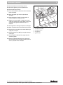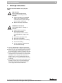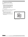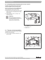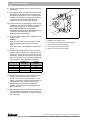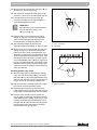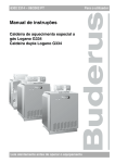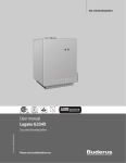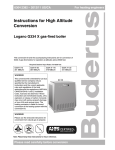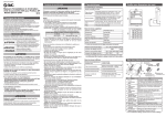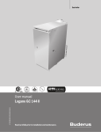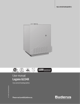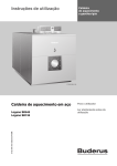
1
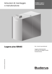
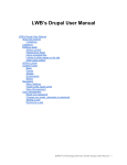
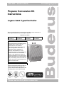
For heating engineers
6304 2381 – 2012/11 US/CA
Propane Conversion Kit
Instructions
Logano G334 X gas-fired boiler
This conversion kit and the accompanying instructions are for conversion of
G334 X gas-fired boilers from natural gas to propane.
Required Input Rates
G334 X-73
301 MBtu/hr
G334 X-92
378 MBtu/hr
G334 X-116
476 MBtu/hr
G334 X-132
541 MBtu/hr
WARNING!
This conversion kit is intended for use by a
qualified service company only as
specified by the manufacturer’s
instructions and the current applicable
rules and regulations of the local
authorities and the regulations of
NFPA54, CAN/CGA B149.1 and 2,
Installation Code, must also be observed.
If these instructions are not followed
exactly, a fire, explosion or release of
carbon monoxide may occur with serious
property damage or loss of life and serious
injury. The heating contractor is liable for
correct conversion of the heating system
with this conversion kit.
CAUTION!
Before converting the heating system to a
different type of gas the gas line must
first be shut off and then the power to the
heating system must be disconnected.
Note: Please keep these instructions for future reference.
Please read carefully before conversion
Contents
1
Safety .
. . . . . . . . . . . . . . . . . . . . . . . . . . . . . . . . . . . . . . . . . . . . . . . . . . . . 3
1.1 Correct use . . . . . . . . . . . . . . . . . . . . . . . . . . . . . . . . . . . . . . . . . . . . . . . 3
1.2 Notes structure. . . . . . . . . . . . . . . . . . . . . . . . . . . . . . . . . . . . . . . . . . . . . 3
1.3 Please observe these notes . . . . . . . . . . . . . . . . . . . . . . . . . . . . . . . . . . . . . 3
2
Scope of delivery .
3
Conversion to propane
4
Start-up instructions
. . . . . . . . . . . . . . . . . . . . . . . . . . . . . . . . . . . . . . . . . . . 3
. . . . . . . . . . . . . . . . . . . . . . . . . . . . . . . . . . . . . . . 4
. . . . . . . . . . . . . . . . . . . . . . . . . . . . . . . . . . . . . . . . . 9
4.1 Making boiler ready for operation . . . . . . . . . . . . . . . . . . . . . . . . . . . . . . . . 10
4.2 Then carry out start-up procedures. . . . . . . . . . . . . . . . . . . . . . . . . . . . . . . . 11
We reserve the right to make any changes due to technical modifications.
2
Instructions for conversion kit for Logano G334 X gas-fired boiler • Issue 2012/11
Safety
1
1
Safety
Observe these instructions for your safety.
1.1
Please observe these notes
RISK TO LIFE
Correct use
The conversion set is supplied for conversion of the
G334X gas-fired heater from natural gas to propane.
1.2
1.3
from explosion of flammable gases.
WARNING!
z Never work on gas lines unless you are
licensed for this type of work.
Notes structure
RISK TO LIFE
Additional symbols for identification of dangers and user
instructions.
from electric shock.
WARNING!
RISK TO LIFE
Identifies possible dangers emanating
from a product, which might lead to serious
WARNING!
injury or death if appropriate care is not
taken.
z Disconnect the power supply to the
heating system before conducting any
work on it, e.g. switch off the heating
emergency switch outside the boiler
room.
z It is not sufficient just to switch off the
control.
RISK TO LIFE
from electric shock.
2
Scope of delivery
USER NOTE
1. Honeywell gas solenoid valve conversion kit
# 393 691, comprising:
WARNING!
Tip for the optimum utilization and setting
of the control(s) plus other useful
information.
– black safety screw
– pressure adjustment screw
– red spring
– yellow label for gas valve
2. 2 BBR 12 ignition gas orifices
3. main gas orifices and seals
4. unit label (to be filled out and attached to the unit)
5. Technical documents
We reserve the right to make any changes due to technical modifications.
Instructions for conversion kit for Logano G334 X gas-fired boiler • Issue 2012/11
3
3
3
Conversion to propane
Conversion to propane
Read the instructions before conversion for your safety.
RISK TO LIFE
WARNING!
due to not observing the attached
conversion instructions.
z If you wish to convert the boiler for
operation with propane, the conversion
from natural gas to propane must be
carried out first as specified by the
attached conversion instructions.
The following instructions must be followed for
conversion of the boiler to propane:
1. If the boiler has been operating, close the gas valve.
Otherwise continue with step 3.
2. Disconnect heating system from the power supply
and set the thermostat to the lowest setting.
3. Remove safety screws from the left and right side
panels, then lift the front panel of the boiler and pull
it forward.
2
1
1
Fig. 1
1
2
Removing front panel of boiler
Screws
Boiler front panel
4. Turn gas valve ON/OFF button clockwise to OFF
position. Do not use force.
RISK TO LIFE
from explosion of flammable gases.
WARNING!
z Wait five (5) minutes until all gas
residues have dissipated. Check
whether there is any smell of gas,
including at floor level. If there is a gas
odor: STOP! Follow instructions in
section “B” of the safety instructions on
Page 9. If there is no sign of a gas odor,
continue with the next step.
Fig. 2
Gas valve
We reserve the right to make any changes due to technical modifications.
4
Instructions for conversion kit for Logano G334 X gas-fired boiler • Issue 2012/11
Conversion to propane
3
Replace main gas orifices
5. Remove the safety screw for the orifice pressure
adjustment on the gas valve.
6. Remove manifold pressure adjustment screw.
1
7. Remove stainless steel spiral spring.
8. Install the red spring from the Honeywell LP
conversion kit in the gas valve.
2
9. Screw in the new gas adjustment screw from the
Honeywell LP conversion kit until it is flush with the
top of the gas valve.
Then turn the manifold pressure adjustment screw
six (6) full revolutions of 360° clockwise. This
corresponds to a pressure preset of approx. 10.0
W.C. This setting must be checked with a pressure
gauge on completion of the conversion.
10. Install new black safety screw from the Honeywell
LP conversion kit.
11. Clean the gas valve housing and attach to yellow
label from the Honeywell LP conversion kit to a
visible spot on the gas valve.
3
4
5
Fig. 3
1
2
3
4
5
Gas valve
Safety screw
Manifold pressure adjustment screw
Stainless steel spiral spring
Gas valve
Yellow label
We reserve the right to make any changes due to technical modifications.
Instructions for conversion kit for Logano G334 X gas-fired boiler • Issue 2012/11
5
3
Conversion to propane
12. Disconnect pilot burner gas line from gas valve.
6
13. Disconnect ignition cable from automatic ignition.
7
RISK TO LIFE
due to incorrectly connected wiring.
WARNING!
z When conducting maintenance work
label all cables before disconnecting
them.
4
5
3
2
1
5
4
3
2
14. Label connection lines of flame roll-out switch and
disconnect from the roll-out switch.
15. Disconnect connection lines to the gas valve.
16. Tie gas line with wire or cord (secure).
1
17. Unscrew retaining screws on gas supply line and on
burner. Place the gas connection pipe gasket in a
safe place.
18. Check gasket for damage and replace if damaged.
19. Unscrew retaining nuts on burner plate and pull gas
burner straight out.
20. When removing the burner make sure that the
spacers remain on the studs.
21. Install the new main gas orifices and copper gasket.
Check with Î Tab. 1 that the correct orifices for
operation of the boiler are installed.
8
Fig. 4
1
2
3
4
5
6
7
8
Removing gas burner
Ignition cable
Flame roll-out switch
Connection lines to the gas valve
Gas valve
Connection lines to the flame roll-out switch
Gas supply line
Retaining screw on the gas feed line
Pilot burner gas line
Orifice sizes for propane
Model
Orifice
size
Number
Tab. 1
G334 X-73 G334 X-92 G334 X-116 G334 X-132
235
240
250
250
5
6
7
8
2
2
Orifce sizes
1
USER NOTE
These orifice sizes (Tab. 1) are
exclusively for installations between
0-8500 feet above sea level. Follow the
“Conversion instructions for high
altitudes” for installations between
8501 and 12000 feet above sea level.
1
1
1
Fig. 5
1
2
Removing the gas burner
Fixing nuts
Threaded studs
We reserve the right to make any changes due to technical modifications.
6
Instructions for conversion kit for Logano G334 X gas-fired boiler • Issue 2012/11
Conversion to propane
3
22. Unscrew pilot burner unit from gas burner.
1
23. Disconnect ignition gas line frompilot burner.
24. Remove pilot burner orifice.
25. Place the new BBR 12 pilot burner orifice in the pilot
burner assembly.
26. Screw the ignition gas line to the pilot burner
assembly.
27. Install gas burners in boiler in reverse order of
removal. Tighten the fixing nuts well.
2
28. Tighten the screws (Î Fig. 4 page 6) on the gas
supply line and the burner again. Make sure that the
connection pipe gasket removed in step 17 is
replaced.
3
4
29. Check gasket for damage and replace if damaged.
30. Attach connection lines for the flame roll-out switch.
31. Remove wire or rope that was used to hold the gas
supply line in step 16.
32. Connect pilot gas line (Î Fig. 4 page 6) to the gas
valve again.
Fig. 6
1
2
3
4
Pilot burner assembly (cut-out view)
Pilot burner assembly
Pilot burner orifice
Pilot gas line
Ignition cable
33. Connect ignition cables (Î Fig. 4 page 6) to the
automatic igniters.
34. Enter the required information on the conversion
label and attach on the outside of the boiler jacket as
close as possible to the nameplate.
We reserve the right to make any changes due to technical modifications.
Instructions for conversion kit for Logano G334 X gas-fired boiler • Issue 2012/11
7
3
Conversion to propane
Carrying out leak test
USER NOTE
The boiler has two gas valves. Make all
measurements and adjustments on both
gas valves.
35. Open gas shut-off valve in the gas line.
SYSTEM DAMAGE
due to short-circuit.
CAUTION!
z Cover the hazardous locations before
checking for leaks.
z Do not spray the leak solution on wiring
openings, plugs or electrical
connections. Do not allow the solution
to drip on these locations.
36. Check the gas connection line to the gas valve for
leaks with soap solution. If no leaks are found,
continue with step 38. If any leaks are found, close
gas shut-off valve.
37. Seal leaks and repeat step 36.
38. Close main gas shut-off valve. Remove the screw
plug for the gas pressure measuring port on the gas
valve. Install pressure measuring nipple and attach
a manometer pressure gauge to measure the gas
pressure.
2
39. Remove the screw plug for the manifold pressure
measuring port on the gas valve. Install pressure
measuring nipple and attach a manometer pressure
gauge to measure the manifold pressure.
40. Open gas valve and measure the gas supply
pressure of the boiler. The supply pressure for
natural gas must be between 7" and 10.5" W.C. and
between 11" and 13" W.C. for propane gas. If the
supply pressure for natural gas is not between 7"
and 10.5" W.C. and not between 11" and 13" W.C.
for propane gas, contact the customer service
technician or the gas company.
41. Always follow the start-up instructions on the next
page.
1
3
Fig. 7
1
2
3
Gas valve
ON/OFF button (at ON position)
Screw plug for gas supply pressure measuring port
Screw plug for manifold measuring port
We reserve the right to make any changes due to technical modifications.
8
Instructions for conversion kit for Logano G334 X gas-fired boiler • Issue 2012/11
Start-up instructions
4
4
Start-up instructions
Read the instructions before start-up for your
safety.
RISK TO LIFE
due to not observing the start-up
instructions and resulting incorrect
WARNING!
operation.
z If these instructions are not followed
exactly, a fire or explosion may be
caused with serious property damage
or loss of life or serious injury.
z Observe the start-up instructions.
DANGER OF EXPLOSION
WARNING!
If you smell gas there is a danger of
explosion.
z No open flame. No smoking.
z Prevent spark formation.
Do not operate electrical switches,
including telephones, plugs or door
bells.
z Shut off main gas supply valve.
z Open doors and windows.
z Warn other occupants of the building.
z Evacuate the building.
z Call gas company or fire department
from outside the building.
A This unit is equipped with an igniter that automatically
starts the pilot burner. Do not attempt to ignite it manually.
B Check for an odor of gas around the system. This test must
also be conducted at floor level, because some types of
gas are heavier than air and may accumulate at floor level.
C Switch on the ON/OFF switch on the gas valve by hand
only. Never use a tool as assistance. If you cannot actuate
the ON/OFF switch on the gas valve by hand, do not
attempt to repair it. Contact a qualified technician. Any
attempt to use force or to repair the switch may cause a fire
or explosion.
D Do not operate the unit if any part is under water. Contact
a qualified customer service technician immediately to
have the unit checked and to replace the parts of the
control and gas valves that were under water.
We reserve the right to make any changes due to technical modifications.
Instructions for conversion kit for Logano G334 X gas-fired boiler • Issue 2012/11
9
4
4.1
Start-up instructions
Making boiler ready for operation
STOP! First read the safety instructions on Î page 9 of
this manual.
1. Carry out leak test (Î page 8). Wait five (5) minutes
until all gas residues have dissipated. Finally check
whether there is any smell of gas, including at floor
level. If there is a gas odor: STOP! Follow
instructions in section “B” of the safety instructions
on Î page 9 of this manual. If there is no sign of a
gas odor, continue with the next step.
2. Open main gas valve.
4.1.1 Placing heating system with aquastat control in operation
The boiler is fully functional with the factory-installed
aquastat.
3. Switch on ON/OFF switch (building side)
(ON position). This switches on the boiler with all its
components. Then continue with step 7.
4. Make sure that the room thermostat signals a heat
requirement (set thermostat at least 10 °F above
room temperature).
1
Fig. 8
1
Switching on heating system (with aquastat)
ON/OFF switch (main switch)
We reserve the right to make any changes due to technical modifications.
10
Instructions for conversion kit for Logano G334 X gas-fired boiler • Issue 2012/11
Start-up instructions
4
4.1.2 Placing heating system with Logamatic 2107 (accessory) in operation
The boiler is fully functional with the factory-installed
aquastat. The Logamatic 2107 control can also be
installed in addition to the factory-installed aquastat.
Switch on the heating system with the ON/OFF switch
on the control. The burner starts operating if heat is
required (Î observe control service manual).
5. Make sure that heat is required at the control. Select
“Manual operation” (hand symbol) with the mode
selector switch.
6. Switch on ON/OFF switch (“I” position). Then
continue with step 7.
USER NOTE
After carrying out the instructions for
starting described below, the control must
be set to “AUT” mode (automatic
operation) with the mode selector.
1
Fig. 9
1
2
4.2
2
Switching on heating system (with Logamatic 2107
control)
Mode selection switch
ON/OFF switch
Then carry out start-up procedures.
The following start-up procedures must be carried out
regardless of the control type.
7. Look at the igniter through the sight glass in the
burner housing.
1
Fig. 10
1
Front view
Sight glass
We reserve the right to make any changes due to technical modifications.
Instructions for conversion kit for Logano G334 X gas-fired boiler • Issue 2012/11
11
4
Start-up instructions
8. Turn gas valve ON/OFF switch counterclockwise to
ON position.
2
9. The automatic igniter must generate sparks towards
the pilot burner. The pilot flame must appear and
then ignite the main burner. If the main burner does
not ignite, close the gas valve. Disconnect heating
system from the power supply and inform your
customer service technician or gas company.
3
10. If the main burner has ignited, the gas valve must be
checked for leaks with soap solution. If no leaks are
found, continue with step 12. If leaks have been
found, switch ON/OFF switch on gas valve
clockwise to the OFF position. Disconnect heating
system from the power supply and set the
thermostat to the lowest setting.
11. Seal leaks. Repeat steps 1 and 2 (regardless of the
control in use).
Caution:
With aquastat control continue with steps 3 and 4,
with the Logamatic 2107 continue with steps 5
and 6.
Then repeat steps 7 to 10 regardless of the control
in use.
1
5
4
Fig. 11
1
2
3
4
5
Gas valve
ON/OFF button (at ON position)
Screw plug for gas supply pressure measuring port
Safety screw for inlet pressure setting
Screw plug for manifold measuring port
Safety screw for pilot pressure setting
12. Check the gas supply pressure at the connection
while the boiler is operating. The supply pressure for
natural gas must be between 7" and 10.5" W.C. and
between 11" and 13" W.C. for propane gas. Record
the measured values in the commissioning protocol
in the installation and maintenance instructions.
G334 X
73
92
116
132
Tab. 2
Natural gas
inch W.C.
4.4
4.4
4.1
4.2
Propane
inch W.C.
10.4
10.3
10.3
10.2
Manifold pressure
13. Check manifold pressure. The manifold pressure
must be set in accordance with the values in
Î Tab. 2. To set the manifold pressure the cover
(Î Fig. 11) on the gas valve must be removed. Turn
the adjustment screw clockwise to increase the
pressure and counterclockwise to reduce the
pressure. This setting must be adjusted while the
boiler is operating.
14. Record the set value in the commissioning protocol
of the installation and maintenance instructions and
screw the safety screw (Î Fig. 11 page 12) into the
gas valve again.
We reserve the right to make any changes due to technical modifications.
12
Instructions for conversion kit for Logano G334 X gas-fired boiler • Issue 2012/11
Start-up instructions
4
15. Observe pilot flame through the sight glass (Î Fig.
10 page 11) in the burner housing.
1
16. The flame must envelope the flame guard 1/2 to 1
1/2 inches. If this is the case continue with step 20.
17. If the pilot flame is too small or too large, the
pressure for the pilot must be adjusted with the
corresponding adjustment screw.
USER NOTE
2
The adjustment screw is behind the pilot
pressure adjustment safety screw
(Î Fig. 11 page 12).
18. Remove safety screw for pilot pressure setting
(Î Fig. 11 page 12). Turn the inner adjustment
screw clockwise to reduce the pilot flame and
counterclockwise to enlarge the pilot flame.
Fig. 12
19. After adjustment tighten the pilot pressure
adjustment safety screw (Î Fig. 11 page 12) again.
1
2
Correct pilot flame setting
1/2 to 1 1/2 inches
Pilot flame
20. Observe main burner flame through the sight glass
(Î Fig. 10 page 11) in the burner housing. The
flame must have a steady and fixed contour and
generally has a bluish color. If the main burner flame
meets the requirements, proceed with step 21. If the
main burner flame is too weak or is yellow or goes
out, turn the ON/OFF switch (Î Fig. 11 page 12) on
the gas valve clockwise to OFF. Close the gas valve
and disconnect the heating system from the power
supply and contact the customer service technician
or the gas company.
1
Checking ignition safety switch
21. Test the safety switch by closing the gas shut-off
valve. The main burner flame (Î Fig. 13) and the
pilot flame (Î Fig. 12) are extinguished. After six (6)
seconds at the most the main gas solenoid valve on
the gas valve must close with an audible noise.
22. After 90 seconds the automatic igniter must switch
to lock status and stop generating sparks.
Fig. 13
1
Main burner
Main burner flame
23. Disconnect the heating system from the power
supply. Open main gas shut-off valve. Switch on unit
power supply. A normal operating cycle must follow.
24. If the gas valve operates correctly, proceed to
step 25. If the gas valve does not operate correctly,
switch ON/OFF switch (Î Fig. 14) on the gas valve
clockwise to the OFF position immediately. Close
main gas shut-off valve. Disconnect heating system
from the power supply and inform the customer
service technician or gas company.
We reserve the right to make any changes due to technical modifications.
Instructions for conversion kit for Logano G334 X gas-fired boiler • Issue 2012/11
13
4
Start-up instructions
25. Turn gas valve ON/OFF button clockwise to OFF
position.
26. Close main gas shut-off valve.
27. Disconnect heating system from the power supply
and set the thermostat to the lowest setting.
28. Remove pressure measuring nipple and pressure
gauge for measuring gas supply pressure and
manifold pressure from the gas valve and close the
openings with the screw plugs.
29. Repeat steps 1 to 10 (depending on the control) and
20 to restart the heating system. Check the screw
plugs for leaks with soap solution. If no leaks are
found, continue with step 31. If leaks are found,
close gas shut-off valve and switch ON/OFF button
on gas valve clockwise to the OFF position.
Disconnect the heating system from the power
supply.
30. Seal leaks. Open gas shut-off valve and repeat
step 24.
1
Fig. 14
1
Gas valve
ON/OFF button (at OFF position)
31. Carefully wipe away the soap solution to prevent
corrosion caused by the alkali content of the soap.
32. Check the function of the maximum aquastat to
make sure that it switches off the boiler as soon as
the boiler water temperature set at the aquastat or
the Logamatic 2107 control is reached. Record the
result in the commissioning protocol of the
installation and maintenance instructions.
33. Replace front panel of boiler.
With the Logamatic 2107 control only
34. Select AUT (automatic mode) with the mode
selection switch.
We reserve the right to make any changes due to technical modifications.
14
Instructions for conversion kit for Logano G334 X gas-fired boiler • Issue 2012/11
Notes
We reserve the right to make any changes due to technical modifications.
Instructions for conversion kit for Logano G334 X gas-fired boiler • Issue 2012/11
15