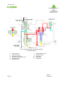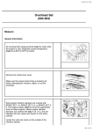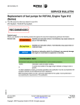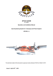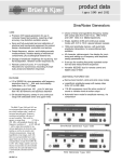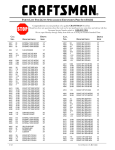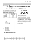
1
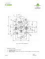
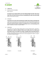
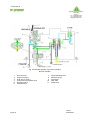
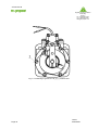
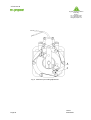
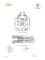
ATA 61-20-46
(E-1046)
OPERATION AND INSTALLATION MANUAL
HYDRAULIC REVERSIBLE PROPELLER GOVERNOR
P-9( )( )-( ) series
Issue No.3 : April 20th, 2005
LBA-approved
EASA DE.21G.0008
EASA.21J.020
ATA 61-20-46
Flugplatz Straubing-Wallmühle
94348 Atting
Germany
Tel: +49/(0)9429-9409-0
Fax: +49/(0)9429-8432
[email protected]
TABLE OF CONTENTS
Page
Table of Contents
1
List of Figures
2
List of Revisions
3
List of Effective Pages
4
1. General
5
2. Design Information
5
3. Operation Information
11
4. Governor Specification (Basic Parameters and Technical Data)
15
5. Governor Inspection
16
6. Installation Instruction
16
7. Adjustment of Control Head
17
8. Intentionally left blank
19
9. Adjustment of Maximal Propeller RPM
19
10. Adjustment of Relief Valve
22
11. Aircraft Flight Check
22
12. Governor Flange Gasket Change
24
13. Removing the Governor from Engine
24
14. Governor Conservation
24
15. Troubleshooting
25
16. Shipping and Storage
26
17. Maintenance
26
Page 1
Issue 1
2004/04/01
ATA 61-20-46
Flugplatz Straubing-Wallmühle
94348 Atting
Germany
Tel: +49/(0)9429-9409-0
Fax: +49/(0)9429-8432
[email protected]
LIST OF FIGURES
Page:
Fig.
1
P-9( )( )-( ) Propeller Governor (general view)
6
Fig.
2
P-9( )( )-( ) Propeller Governor (side view)
7
Fig.
3
P-9( )( )-( ) Propeller Governor (dimensions)
8
Fig.
4
P-9( )( )-( ) Propeller Governor (longitudinal sectional view)
9
Fig.
5
View at Governor Flange
10
Fig.
6
Schematic Diagram of Operation - normal operation
12
Fig.
7
Schematic Diagram of Operation - reversing operation
14
Fig.
8
Positioning of Control Head
19
Fig.
9
Maximum rpm Adjustment
21
Fig.
10
Relief Valve Unlocking
22
Fig.
11
Relief Valve Adjustment
22
Page 2
Issue 1
2004/04/01
ATA 61-20-46
Flugplatz Straubing-Wallmühle
94348 Atting
Germany
Tel: +49/(0)9429-9409-0
Fax: +49/(0)9429-8432
[email protected]
LIST OF REVISIONS
Issue
1
2
Date of Issue
2004-04-01
2004-09-13
Page
all
3, 4, 16
3
2005-04-20
3, 4, 22
Page 3
Short Description
Original Issue
Item 4.3.4:
Update of TBO
Small corrections to
item 10.0
Issue 3
2005/04/20
ATA 61-20-46
Flugplatz Straubing-Wallmühle
94348 Atting
Germany
Tel: +49/(0)9429-9409-0
Fax: +49/(0)9429-8432
[email protected]
LIST OF EFFECTIVE PAGES
Page
1
2
3
4
5
6
7
8
9
10
11
12
13
14
15
16
17
18
19
20
21
22
23
24
25
26
Page 4
Date of Issue
2004/04/01
2004/04/01
2005/04/20
2005/04/20
2004/04/01
2004/04/01
2004/04/01
2004/04/01
2004/04/01
2004/04/01
2004/04/01
2004/04/01
2004/04/01
2004/04/01
2004/04/01
2004/09/13
2004/04/01
2004/04/01
2004/04/01
2004/04/01
2004/04/01
2005/04/20
2004/04/01
2004/04/01
2004/04/01
2004/04/01
Issue 3
2005/04/20
ATA 61-20-46
Flugplatz Straubing-Wallmühle
94348 Atting
Germany
Tel: +49/(0)9429-9409-0
Fax: +49/(0)9429-8432
[email protected]
P-9( )( )-( ) SERIES HYDRAULIC PROPELLER GOVERNOR
INSTALLATION- AND OPERATION MANUAL
1.0 GENERAL
The P-9( )( )-( ) hydraulic propeller governor is a single acting governor developed for hydraulically
variable pitch propellers with reverse and feathering, produced by AVIA Propeller for
MT-Propeller, Straubing. See fig. 1/fig. 1.1.
DESIGNATION:
P-9( )( )-( )
a b
S/No. 04 G 003
a
b
a = Drawing No.
b = Application No. (Engine/Aircraft combination)
a = Year of Manufacture
G = governor
b = consecutive No.
2.0 DESIGN INFORMATION
Also refer to fig. 2, 3, 4, and 5
The governor is a dual pressure single acting system. It is designed for oil pressure to decrease
pitch. The governor has one relief valve with pressure settings. The low pressure setting is for normal
operation and the high pressure relief valve setting is for reverse/beta range.
In low pressure operation the necessary increase of the engine oil pressure is assured by a gear
pump in the governor, which increases the oil servo pressure. Flyweights and a speeder spring move
a pilot valve, allowing servo oil to flow to or from the piston in the propeller. In "on-condition” there is
no oil flow.
A speed adjusting lever changes the pre-load of the speeder spring. This results in an
engine/propeller speed change.
The high pressure mode is activated via a magnetic beta valve, which is installed on the governor. In
this condition the pressure rises up approx. twice and pushes the blades into full reverse. During high
pressure mode the propeller rpm is not controlled by the governor because the constant speed
section is cut out. The negative thrust is set by increasing and decreasing the engine power (rpm).
After the electric signal is switched off, the governor returns into normal operation pressure mode for
constant speed operation.
The governor contains a gear pump, a relief valve, a pilot valve, flyweights, the beta valve and a
solenoid valve.
The flange type of the governor is in accordance with ADN 20010 standard, refer also to fig. 5. The
solenoid valve is installed on the top of the governor. The solenoid valve controls the beta valve,
which changes from low pressure to high pressure mode via an electric signal, which is produced by
a switch inside the cockpit. If the high pressure mode is selected, the pilot valve is inoperative.
The control lever is installed on the head of the governor, its angular position can be changed by
turning the cover assembly.
Page 5
Issue 1
2004/04/01
ATA 61-20-46
Flugplatz Straubing-Wallmühle
94348 Atting
Germany
Tel: +49/(0)9429-9409-0
Fax: +49/(0)9429-8432
[email protected]
Fig. 1 P-9( )( )-( ) Propeller Governor - General View
Page 6
Issue 1
2004/04/01
ATA 61-20-46
Flugplatz Straubing-Wallmühle
94348 Atting
Germany
Tel: +49/(0)9429-9409-0
Fax: +49/(0)9429-8432
[email protected]
Fig. 2 P-9( )( )-( ) Propeller Governor (side view)
1 - Solenoid valve
2 - Speed adjusting lever
Page 7
Issue 1
2004/04/01
ATA 61-20-46
Fig. 3 P-9( )( )-( ) Propeller Governor (dimensions)
Flugplatz Straubing-Wallmühle
94348 Atting
Germany
Tel: +49/(0)9429-9409-0
Fax: +49/(0)9429-8432
[email protected]
Page 8
Issue 1
2004/04/01
ATA 61-20-46
Flugplatz Straubing-Wallmühle
94348 Atting
Germany
Tel: +49/(0)9429-9409-0
Fax: +49/(0)9429-8432
[email protected]
Fig. 4
1.
2.
3.
4.
5.
6.
7.
8.
Page 9
P-9( )( )-( ) Propeller Governor (longitudinal sectional view)
Speed adjusting lever
Return spring
Speed adjusting shaft
Speeder spring
Head with flyweights
Shaft
Relief valve plunger
Governor body
9.
10.
11.
12.
13.
14.
15.
16.
Gear pump
Governor base
Pilot valve
Governor drive
Pressure changing valve
Switching valve
Solenoid
Contacts
Issue 1
2004/04/01
ATA 61-20-46
Flugplatz Straubing-Wallmühle
94348 Atting
Germany
Tel: +49/(0)9429-9409-0
Fax: +49/(0)9429-8432
[email protected]
Fig. 5 Governor flange ADN 20010
Designation of channels
I
II
III
Page 10
Oil supply from the engine oil system
Propeller oil supply
Return oil from the propeller hub and from the internal leakage of the governor into the
engine oil system
Issue 1
2004/04/01
ATA 61-20-46
3.0
OPERATION
3.1
Normal operation (on-speed)
Flugplatz Straubing-Wallmühle
94348 Atting
Germany
Tel: +49/(0)9429-9409-0
Fax: +49/(0)9429-8432
[email protected]
Refer to page 12.
If the governor is in on-speed condition, the actual speed and selected speed are equal, force of
the speeder spring is balanced with force of the rotating flyweights. The pilot valve plunger
covers ports so oil cannot flow to or drain from the propeller servo piston. Oil from the gear
pump overcomes relief valve spring force and is circulated through the open relief valve plunger
back to the inlet side of the pump.
3.2
Overspeed
This condition occurs when actual propeller speed is greater than selected. The flyweights pivot
outward and they overcome the force exerted by the speeder spring. Flyweight toes lift the pilot
valve plunger, uncovering ports in the shaft, allowing oil in servo to drain from the propeller servo
piston. The propeller servo piston increases pitch, engine load is increased and propeller speed
is reduced until selected speed is obtained. The flyweights return to a normal position and the
pilot valve plunger covers ports in the shaft blocking the flow of oil to or from the propeller servo
piston. The governor is back in on-speed condition.
3.3
Underspeed
This condition occurs when actual propeller speed is less than selected speed. A decrease in
centrifugal force causes the rotating flyweights to pivot inward under force exerted by the
speeder spring. The pilot valve plunger is forced down uncovering ports in the shaft allowing
pressurized oil to flow to the propeller servo piston. The propeller servo piston decreases pitch,
thus reducing load on the engine and increasing propeller speed until selected speed is
obtained. The flyweights return to a normal position and the pilot valve plunger covers ports in
the shaft, blocking the flow of high pressure oil to or from the propeller servo piston. The governor is back in on-speed condition.
Overspeed
Page 11
On-speed
Underspeed
Issue 1
2004/04/01
ATA 61-20-46
Flugplatz Straubing-Wallmühle
94348 Atting
Germany
Tel: +49/(0)9429-9409-0
Fax: +49/(0)9429-8432
[email protected]
Fig. 6 Schematic diagram of governor operation
Normal operation
1.
2.
3.
4.
5.
6.
Page 12
Gear oil pump
Engine oil supply
Drain line (to sump)
Control line for propeller servo
Reversing valve
Solenoid valve
7.
8.
9.
10.
11.
Speed adjusting lever
Speeder spring
Flyweights
Pilot valve
Relief valve
Issue 1
2004/04/01
ATA 61-20-46
3.4
Reversing
Flugplatz Straubing-Wallmühle
94348 Atting
Germany
Tel: +49/(0)9429-9409-0
Fax: +49/(0)9429-8432
[email protected]
Refer to page 14.
Via an electric signal to the solenoid beta valve, the switching control valve changes the position,
the reversing valve moves to reversing position and thus relief valve changes its setting to high
pressure. At the same time, control line for propeller servo will be connected with governor high
pressure line and pushes the propeller into full reverse. In this condition the pilot valve is
inoperative, therefore the propeller is not controllable by the constant speed section in the
governor. The negative thrust must be produced by increasing and decreasing the engine power
(engine rpm).
Page 13
Issue 1
2004/04/01
ATA 61-20-46
Flugplatz Straubing-Wallmühle
94348 Atting
Germany
Tel: +49/(0)9429-9409-0
Fax: +49/(0)9429-8432
[email protected]
Fig. 7 Schematic diagram of governor operation
Reversing operation
1.
2.
3.
4.
5.
6.
Page 14
Gear oil pump
Engine oil supply
Drain line (to sump)
Control line for propeller servo
Reversing valve
Solenoid valve
7.
8.
9.
10.
11.
Speed adjusting lever
Speeder spring
Flyweights
Pilot valve
Relief valve
Issue 1
2004/04/01
ATA 61-20-46
Flugplatz Straubing-Wallmühle
94348 Atting
Germany
Tel: +49/(0)9429-9409-0
Fax: +49/(0)9429-8432
[email protected]
4.0
GOVERNOR SPECIFICATION
4.1
Basic Parameters
4.1.1
4.1.2
4.1.3
4.1.4
4.1.5
4.1.6
Weight
Dimensions
Drive
Governor rotation facing base
Propeller speed control
Governor drive ratio
max. 1.7 kg
see fig. 3
from engine
CCW / CW
lever
according to engine
4.1.7
Operating liquid
piston engine oil from engine oil system
4.1.8
Operating voltage
24 or 12 V
4.2
Technical Data
4.2.1
Supply oil pressure
3 + 0,3 bar
(43,5 ± 4,4 psi)
4.2.2
High pressure relief valve setting,
at 90 % of max. governor rpm,
oil temperature 75 + 3°C (170°F)
38,5 ± 1,5 bar
(558 ± 22 psi)
4.2.3
Low pressure relief valve setting,
at max. governor rpm,
oil temperature 75 + 3 ° C (170°F)
22 bar + 1 bar
320 psi + 10 psi
4.2.4
Range of operating temperatures for
full accuracy
+20 to + 80°C (+68 to + 176°F)
4.2.5
Full range of operating temperatures
-20 to + 110°C (-4 to +230°F)
4.2.6
Pump capacity at 1.750 + 10 governor rpm,
min. 7 l/min (7,5 qu/min)
3 + 0,3bar(43,5 psi) input oil pressure,
75+ 3°C (170°F) oil temperature,
oil pressure at output approx.10 + 0,5 bar (145±7psi)
4.2.7
Range of governed speed
1.000 to 3.000 rpm
4.2.8
Internal leakage at 1.750 rpm,
output pressure 18 ± 1 bar,
temperature 75 + 3°C (170°F)
max. 2.0 l/hour (2,1 qu/min)
4.2.9
Governor stability
±5%
4.2.10
Total control arm angular travel
max. 90°
4.2.11
Table of Governor Types:
For all governor types please refer to MT-Propeller Governor List E-1057.
Page 15
Issue 1
2004/04/01
ATA 61-20-46
Flugplatz Straubing-Wallmühle
94348 Atting
Germany
Tel: +49/(0)9429-9409-0
Fax: +49/(0)9429-8432
[email protected]
4.3
Operational Conditions
4.3.1
Altitude
0 to 8.500 m (0 to 28000ft)
4.3.2
Temperature ranges
-20 to +110°C (-4 to + 230°F)
4.3.3
Flight maneuvering load factor
+8g, -5g
4.3.4
Time between overhaul
1.500 flying hours or 6 calendar years
4.3.5
Maximum permitted RPM
3500 RPM (continuously) for standard
reciprocating engines
5.0
GOVERNOR INSPECTION BEFORE INSTALLATION ON THE ENGINE
After unpacking, the governor must be inspected, whether it is damaged (for example after
drop, etc.) and for damaged parts. In case you have found a damage caused by
transportation, please, contact the forwarder immediately, as well as the supplier.
6.0
INSTALLATION INSTRUCTION
6.1
Clean engine and governor flange with solvent or gasoline. Both surfaces must be dry and
clean. Remove all surface defects.
6.2
Install clean, silicone greased gasket on engine flange. Gasket must have a screen on the
inlet (supply) parts. Turn governor drive by hand to check free turning. Install the governor on
the engine flange. The splines of the governor shaft must fit into the splines of drive in the
engine. Mounting bolts or stop nuts with washers should be torqued crosswise with 20-24 Nm
(180 - 220 inlb).
Warning:
Loosen bolts or nuts can cause improper function of the governor or at least oil leakage.
6.3
Connect control rod to governor control lever (according to the instruction in the aircraft
service manual).
6.4
Plug in wiring for the reverse switching (beta) valve.
6.5
Perform a functional check and inspection for leakage according to chapter 11 in this
manual.
Page 16
Issue 2
2004/09/13
ATA 61-20-46
Flugplatz Straubing-Wallmühle
94348 Atting
Germany
Tel: +49/(0)9429-9409-0
Fax: +49/(0)9429-8432
[email protected]
7.0
CONTROL HEAD / LEVER ADJUSTMENT
It is possible to position the governor head / control lever to any position, see fig. 8.
7.1
Governor head / control lever rearrangement instructions:
7.1.1
Remove one safety wires from six screws position 1, fig. 8.
7.1.2
Loosen these six screws such a way, that it is possible to turn with the control head.
7.1.3
Turn the control head to desired position.
7.1.4
Tighten the six screws, secure with lock wire AMS5687 or equivalent, according to fig. 8.
Page 17
Issue 1
2004/04/01
ATA 61-20-46
Flugplatz Straubing-Wallmühle
94348 Atting
Germany
Tel: +49/(0)9429-9409-0
Fax: +49/(0)9429-8432
[email protected]
Fig. 8 Positioning of governor P-9( )( )-( ) control head
Page 18
Issue 1
2004/04/01
ATA 61-20-46
Flugplatz Straubing-Wallmühle
94348 Atting
Germany
Tel: +49/(0)9429-9409-0
Fax: +49/(0)9429-8432
[email protected]
8.0
Intentionally left blank
9.0
ADJUSTING OF MAXIMAL PROPELLER RPM
Note:
It is possible to set maximum rpm with the described procedure only in a limited range. This is a
normal maintenance procedure and fully authorized.
9.1
Remove lock wire from the stop screw (fig. 9, pos. 1) and loosen the lock nut (2) of the screw
(1).
9.2
Place the governor lever on maximum rpm stop. Change maximum speed stop screw until
proper speed setting is reached. Torque check nut.
9.3
Secure the lever with lock washer and screw 4 - 5 Nm (35-44 inlb).
Page 19
Issue 1
2004/04/01
ATA 61-20-46
Flugplatz Straubing-Wallmühle
94348 Atting
Germany
Tel: +49/(0)9429-9409-0
Fax: +49/(0)9429-8432
[email protected]
Fig. 9 Maximum rpm setting adjustment
Page 20
Issue 1
2004/04/01
ATA 61-20-46
Flugplatz Straubing-Wallmühle
94348 Atting
Germany
Tel: +49/(0)9429-9409-0
Fax: +49/(0)9429-8432
[email protected]
Fig. 10 Relief valve unlocking
For fig. 10 and 11:
1. Safety pin
2. Plug
3. Governor base
4. Adjusting shim
5. Spring
6. Governor body
7. Plunger
Page 21
Fig. 11 Relief valve adjustment
8.
9.
10.
11.
12.
Guide
Reversing valve
Bushing
Idler
Pin
Issue 1
2004/04/01
ATA 61-20-46
Flugplatz Straubing-Wallmühle
94348 Atting
Germany
Tel: +49/(0)9429-9409-0
Fax: +49/(0)9429-8432
[email protected]
10.0 ADJUSTMENT OF RELIEF VALVE
Fig. 10 and Fig. 11.
10.1 Remove safety pin (1) from relief valve plug (2), apply adequate force onto the plug to release
the safety pin.
10.2 Remove the plug (1) from the idler pin (12). Check the number of shims under the plug.
Note:
Do not lose shim(s) during removing.
10.3 Adjust relief valve pressure by changing thickness of the adjusting shims (4).
Note:
0,1 mm of total length of the shim set is about 10 psi.
Discard one shim is about 50 psi pressure reduction.
10.4 Insert the set of the adjusting shims into the idler pin. Install the relief valve plug and secure with
safety pin.
Note:
This procedure sets both pressures (for normal operation and for reverse) at the same time.
Reverse/high pressures cannot be adjusted separately.
11.0 AIRCRAFT FLIGHT CHECK
Before Static Run-up check feathering on feathering governors in accordance with aircraft
service instructions or pilot manual.
11.1 PERFORM STATIC RUN-UP:
ATTENTION:
PERFORM THE STATIC RUN UP ON A CLEAN AREA , TO NOT DAMAGE THE
PROPELLER BLADES DUE TO STONES ETC.
Lock aircraft brakes. Place cockpit propeller RPM lever in high position. Advance throttle slowly
to maximum permitted engine manifold pressure limits. Record propeller RPM. If local wind
conditions are over 2.5 m/s, 5 knots repeat check with aircraft pointed to opposite direction and
average two numbers. As a general rule, propeller should be 25-100 RPM blow the red line limit
during check.
PULL BACK THE PROPELLER LEVER 3 TO 5 TIMES TO BLEED THE SYSTEM TO REMOVE THE
AIR.
11.2 PERFORM FLIGHT TEST
During takeoff acceleration, record maximum propeller RPM. When sufficient altitude is
reached, level out aircraft, leaving propeller control in full RPM position. Maintain this setting for
3 to 5 minutes while monitoring propeller RPM. Following this check, two conditions may exist
which require adjustment:
Page 22
Issue 3
2005/04/20
ATA 61-20-46
Flugplatz Straubing-Wallmühle
94348 Atting
Germany
Tel: +49/(0)9429-9409-0
Fax: +49/(0)9429-8432
[email protected]
11.2.a
If the propeller RPM is exceeding the redline limit, reduce it to the redline using propeller
control. Leaving propeller at this redline RPM setting, land aircraft and shutdown. Remover
cowling and note position of control arm and governor. Adjust governor high RPM screw
clockwise so it just touches stop on governor control arm; this will ensure that the correct arm
position for governor redline RPM setting cannot be exceeded.
11.2.b
If the propeller is bellow red line limit with max RPM setting on the propeller cockpit control,
note RPM and land. Remove engine cowling and adjust the governor high RPM screw, 1 turn
counterclockwise will result in approximately 25 RPM higher. Perform another flight to
confirm adjustment were sufficient.
Remove engine cowling and check for the oil leaks. Oil leaks aren’t permitted.
Make a record in governor installation record.
11.3
GENERAL
Static Run Up
There has been some confusion in the field concerning propeller low blade angle setting, the
governor setting and how it relates to static run-up and take-off RPM.
As a general rule, engine redline RPM cannot be reached during a full power static run-up.
Contrary to popular belief, the governor is not controlling the propeller at this time, the
propeller is against its low pitch stop. Attempting to increase propeller static run-up RPM by
adjusting the governor high RPM screw will have no effect and will probably result in a
propeller overspeed during the take-off roll.
Page 23
Issue 1
2004/04/01
ATA 61-20-46
Flugplatz Straubing-Wallmühle
94348 Atting
Germany
Tel: +49/(0)9429-9409-0
Fax: +49/(0)9429-8432
[email protected]
12.0
GOVERNOR FLANGE GASKET CHANGE
12.1
Remove governor from engine, chapter 13.
12.2
Install the governor with a new gasket to the engine. Surfaces must be clean and smooth.
See chapter 5.
13.0
REMOVING THE GOVERNOR FROM ENGINE
13.1
Disconnect the control rod, refer to engine/aircraft service manual.
13.2
Disconnect cable from the solenoid. Put shipping cap (if applicable) on the solenoid.
13.3
If applicable, remove safety wire from flange-nuts. Remove nuts and washers.
13.4
Remove the governor from the engine. Protect the engine flange by appropriate means.
13.5
Secure governor flange with shipping cap. In case of necessity clean the governor with
cleaning cloth using petrol.
Pay attention that no petrol can enter the governor.
13.6
Put the governor into an appropriate box, store it as mentioned in chapter 16.
14.0
GOVERNOR CONSERVATION
14.1
Clean the governor with a soft brush or an appropriate cloth with petrol.
Note:
Pay attention that no petrol can enter the governor.
14.2
Cover all non varnished areas on the governor with a thin film of light engine oil.
14.3
Treat the governor according the instruction in item 13 and store it according to chapter 16.
14.4
If the governor is conserved and mounted on a engine flange, which is out of operation, it is
necessary to check it’s condition each 6 months. According to this inspection repeat it’s
conservation.
Page 24
Issue 1
2004/04/01
ATA 61-20-46
15.0
TROUBLE SHOOTING
Flugplatz Straubing-Wallmühle
94348 Atting
Germany
Tel: +49/(0)9429-9409-0
Fax: +49/(0)9429-8432
[email protected]
Propeller Surging or "Wandering" - Possible Causes:
15.1
EXCESSIVE TRANSFER BEARING LEAKAGE
Engines with excessive transfer bearing leakage can experience surging since the governor
may not be able to get enough pressure to the propeller. This causes a delay in propeller
responsiveness and by the time the propeller responds to earlier governor inputs, they have
changed, resulting in propeller "wandering".
Solution: Perform a transfer bearing leakage test per engine manufacturer's instructions. If
test indicates a high rate of leakage (even though it may still be on the high side of
"acceptable" tolerance), this maybe your cause. Install the suspect governor on a known
"good" aircraft, if problem disappears, engine work may be indicated.
15.2
MALFUNCTIONING MAGNETOS
See the engine manual.
15.3
DIRTY ENGINE OIL
Contaminants in dirty engine oil can cause blockage of close tolerance passages in governor,
leading to erratic operation.
Solution: Timely engine oil changes should eliminate this problem.
15.4
EXCESSIVE "PLAY" IN AIRCRAFT PROPELLER CONTROL LINKAGE
Excessive "play" in the linkage between the governor and the cockpit control often leads to
erratic operation. Specifically, if the propeller RPM is suddenly changing and holding a new
setting on its own, this could indicate loose linkage.
Solution: Trace linkage and locate unsecured sections and tighten-up as needed.
Please note that although linkage may appear to allow full governor control while the engine
is off, it may not in the air. Engine vibration and "stretch" of the mount during operation can
often aggravate the condition. Therefore, it is important the entire length of linkage be
properly secured, even if both ends alone are tight.
15.5
EXCESSIVE PROPELLER FRICTION
(NOTE: This is rarely the cause of RPM malfunction.)
Propeller may be overly-resistant to pitch movement. This can be caused by either
excessively tight shimming of the propeller blades, or internal corrosion or part failure,
causing binding.
Solution: Check amount of blade ”play" as defined below:
A total lack of blade "shake" may indicate excessively tight blade shims. If this is suspected,
have the propeller checked by a qualified FAA-approved propeller repairman. Note that this
check and any needed correction can usually be performed with the propeller installed on the
aircraft.
Page 25
Issue 1
2004/04/01
ATA 61-20-46
Flugplatz Straubing-Wallmühle
94348 Atting
Germany
Tel: +49/(0)9429-9409-0
Fax: +49/(0)9429-8432
[email protected]
16.0
SHIPPING AND STORAGE
16.1
For any shipment of the governor use original container or box.
In case of returning the governor it is furthermore recommended to return all accessories
and parts together with the governor. They will also be inspected and not considered to be
missing.
16.2
If the governor is stored for a longer period of time, preferably use the original container or
an equivalent one. Storage only in a controlled environment (temperature - 5°F to 95°F, rel.
humidity 10 % to 75 %). Avoid extreme temperature/humidity differences or cycles. All
metal surfaces should have anti-corrosion protection which is easy to remove.
16.3
Long-term storage could require additional preservation. All standard anti-corrosive
preservation oils may be used if they do not affect the seals.
16.4
If the governor is stored or transported in corrosive environment such as salt water or fog, it
is recommendable to cover the visible outside surfaces of the metal parts with a thin film of
light engine oil.
16.5
Before reuse of the governor, clean it inside with engine oil. Pour oil in governor through
channels I, II and III , see fig. 5. Then turn governor drive in direction marked on one side of
the base. Then leave oil to flow out from the governor.
17.0
MAINTENANCE
17.1
There is no maintenance required except for the procedures described in this manual.
17.2
In case of necessity, please, contact service center or governor manufacturer.
Page 26
Issue 1
2004/04/01
ATA 61-20-46
Flugplatz Straubing-Wallmühle
94348 Atting
Germany
Tel: +49/(0)9429-9409-0
Fax: +49/(0)9429-8432
[email protected]