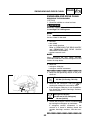
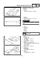
1
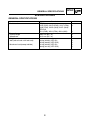
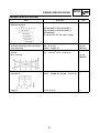
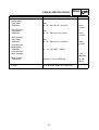
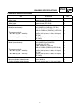
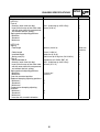
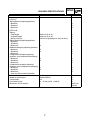
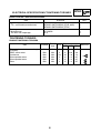
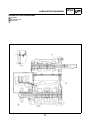
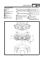
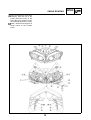
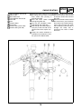
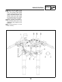
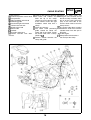
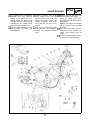
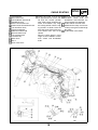
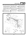
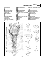
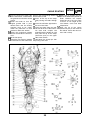
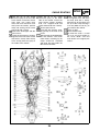
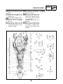
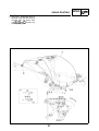
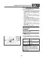
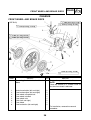
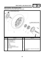
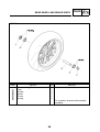
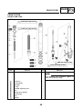
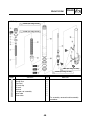
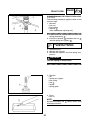
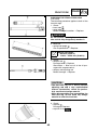
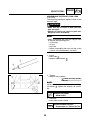
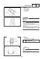
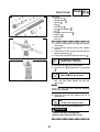
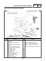
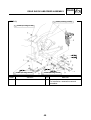
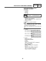
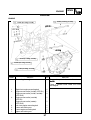
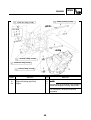
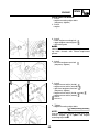
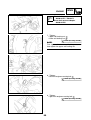
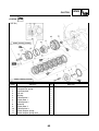
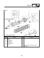
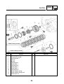
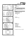
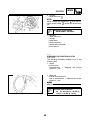
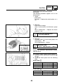
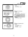
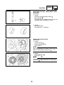
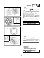
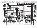
2006
YZF-R1(V)
YZF-R1S(V)
5VY-28197-E2
SUPPLEMENTARY
SERVICE MANUAL
FOREWORD
This Supplementary Service Manual has been prepared to introduce new service and data for the
YZF-R1 (V) / YZF-R1S (V) 2006. For complete service information procedures it is necessary to use
this Supplementary Service Manual together with the following manual.
YZF-R1 (S) 2004 SERVICE MANUAL: 5VY1-AE1
YZF-R1 (V) / YZF-R1S (V) 2006
SUPPLEMENTARY
SERVICE MANUAL
©2005 by Yamaha Motor Co., Ltd.
First Edition, October 2005
All rights reserved.
Any reproduction or unauthorized use
without the written permission of
Yamaha Motor Co., Ltd.
is expressly prohibited.
EAS00002
NOTICE
This manual was produced by the Yamaha Motor Company, Ltd. primarily for use by Yamaha dealers and their qualified mechanics. It is not possible to include all the knowledge of a mechanic in one
manual. Therefore, anyone who uses this book to perform maintenance and repairs on Yamaha
vehicles should have a basic understanding of mechanics and the techniques to repair these types
of vehicles.
Repair and maintenance work attempted by anyone without this knowledge is likely to render the
vehicle unsafe and unfit for use.
Yamaha Motor Company, Ltd. is continually striving to improve all of its models. Modifications and
significant changes in specifications or procedures will be forwarded to all authorized Yamaha dealers and will appear in future editions of this manual where applicable.
NOTE:
Designs and specifications are subject to change without notice.
EAS00004
IMPORTANT MANUAL INFORMATION
Particularly important information is distinguished in this manual by the following.
The Safety Alert Symbol means ATTENTION! BECOME ALERT! YOUR
SAFETY IS INVOLVED!
WARNING
CAUTION:
NOTE:
Failure to follow WARNING instructions could result in severe injury or death
to the vehicle operator, a bystander or a person checking or repairing the
vehicle.
A CAUTION indicates special precautions that must be taken to avoid damage to the vehicle.
A NOTE provides key information to make procedures easier or clearer.
EAS00007
HOW TO USE THIS MANUAL
This manual is intended as a handy, easy-to-read reference book for the mechanic. Comprehensive
explanations of all installation, removal, disassembly, assembly, repair and check procedures are
laid out with the individual steps in sequential order.
The manual is divided into chapters. An abbreviation and symbol in the upper right corner of
each page indicate the current chapter.
Refer to “SYMBOLS”.
Each chapter is divided into sections. The current section title is shown at the top of each page,
except in Chapter 3 (“PERIODIC CHECKS AND ADJUSTMENTS”), where the sub-section title(s)
appears.
Sub-section titles appear in smaller print than the section title.
To help identify parts and clarify procedure steps, there are exploded diagrams at the start of
each removal and disassembly section.
Numbers are given in the order of the jobs in the exploded diagram. A circled number indicates a
disassembly step.
Symbols indicate parts to be lubricated or replaced.
Refer to “SYMBOLS”.
A job instruction chart accompanies the exploded diagram, providing the order of jobs, names of
parts, notes in jobs, etc.
Jobs requiring more information (such as special tools and technical data) are described
sequentially.
EAS00008
SYMBOLS
The following symbols are not relevant to every
vehicle.
Symbols
to
indicate the subject of each
chapter.
General information
Specifications
Periodic checks and adjustments
Chassis
Engine
Cooling system
Fuel injection system
Electrical system
Troubleshooting
Symbols
to
indicate the following.
Serviceable with engine mounted
Filling fluid
Lubricant
Special tool
Tightening torque
Wear limit, clearance
Engine speed
Electrical data
Symbols
to
in the exploded diagrams
indicate the types of lubricants and lubrication
points.
Engine oil
Gear oil
Molybdenum-disulfide oil
Wheel-bearing grease
Lithium-soap-based grease
Molybdenum-disulfide grease
Symbols
to
in the exploded diagrams
indicate the following.
Apply locking agent (LOCTITE®)
Replace the part with a new one.
CONTENTS
GENERAL INFORMATION
SPECIAL TOOLS . . . . . . . . . . . . . . . . . . . . . . . . . . . . . . . . . . . . . . . .
1
SPECIFICATIONS
GENERAL SPECIFICATIONS . . . . . . . . . . . . . . . . . . . . . . . . . . . . . .
ENGINE SPECIFICATIONS . . . . . . . . . . . . . . . . . . . . . . . . . . . . . . . .
CHASSIS SPECIFICATIONS . . . . . . . . . . . . . . . . . . . . . . . . . . . . . . .
ELECTRICAL SPECIFICATIONS. . . . . . . . . . . . . . . . . . . . . . . . . . . .
TIGHTENING TORQUES . . . . . . . . . . . . . . . . . . . . . . . . . . . . . . . . . .
ENGINE TIGHTENING TORQUES . . . . . . . . . . . . . . . . . . . . . . . .
CHASSIS TIGHTENING TORQUES . . . . . . . . . . . . . . . . . . . . . . .
LUBRICATION POINTS AND LUBRICANT TYPES . . . . . . . . . . . . .
ENGINE . . . . . . . . . . . . . . . . . . . . . . . . . . . . . . . . . . . . . . . . . . . . .
CHASSIS . . . . . . . . . . . . . . . . . . . . . . . . . . . . . . . . . . . . . . . . . . . .
LUBRICATION DIAGRAMS . . . . . . . . . . . . . . . . . . . . . . . . . . . . . . . .
CABLE ROUTING. . . . . . . . . . . . . . . . . . . . . . . . . . . . . . . . . . . . . . . .
2
3
5
8
8
8
9
10
10
10
11
12
PERIODIC CHECKS AND ADJUSTMENTS
INTRODUCTION . . . . . . . . . . . . . . . . . . . . . . . . . . . . . . . . . . . . . . . . .
PERIODIC MAINTENANCE AND LUBRICATION INTERVALS . . . .
CHASSIS. . . . . . . . . . . . . . . . . . . . . . . . . . . . . . . . . . . . . . . . . . . . . . .
ADJUSTING THE FRONT FORK LEGS . . . . . . . . . . . . . . . . . . . .
ADJUSTING THE REAR SHOCK ABSORBER ASSEMBLY . . . .
28
28
30
30
33
CHASSIS
FRONT WHEEL AND BRAKE DISCS . . . . . . . . . . . . . . . . . . . . . . . .
REAR WHEEL AND BRAKE DISCS . . . . . . . . . . . . . . . . . . . . . . . . .
REAR BRAKE DISC AND REAR WHEEL SPROCKET . . . . . . . .
FRONT FORK . . . . . . . . . . . . . . . . . . . . . . . . . . . . . . . . . . . . . . . . . . .
FRONT FORK LEGS . . . . . . . . . . . . . . . . . . . . . . . . . . . . . . . . . . .
DISASSEMBLING THE FRONT FORK LEGS . . . . . . . . . . . . . . .
CHECKING THE FRONT FORK LEGS. . . . . . . . . . . . . . . . . . . . .
ASSEMBLING THE FRONT FORK LEGS . . . . . . . . . . . . . . . . . .
REAR SHOCK ABSORBER ASSEMBLY . . . . . . . . . . . . . . . . . . . . .
REMOVING THE REAR SHOCK ABSORBER ASSEMBLY . . . . .
INSTALLING THE REAR SHOCK ABSORBER ASSEMBLY . . . .
SWINGARM AND DRIVE CHAIN . . . . . . . . . . . . . . . . . . . . . . . . . . . .
REMOVING THE SWINGARM . . . . . . . . . . . . . . . . . . . . . . . . . . .
CHECKING THE SWINGARM. . . . . . . . . . . . . . . . . . . . . . . . . . . .
CHECKING THE CONNECTING ROD ASSEMBLY . . . . . . . . . . .
CHECKING THE DRIVE CHAIN . . . . . . . . . . . . . . . . . . . . . . . . . .
36
37
37
39
39
41
43
44
48
50
51
52
52
53
54
55
ENGINE
ENGINE . . . . . . . . . . . . . . . . . . . . . . . . . . . . . . . . . . . . . . . . . . . . .
INSTALLING THE ENGINE . . . . . . . . . . . . . . . . . . . . . . . . . . . . . .
CAMSHAFTS. . . . . . . . . . . . . . . . . . . . . . . . . . . . . . . . . . . . . . . . .
CLUTCH . . . . . . . . . . . . . . . . . . . . . . . . . . . . . . . . . . . . . . . . . . . . . . .
CLUTCH COVER . . . . . . . . . . . . . . . . . . . . . . . . . . . . . . . . . . . . .
CLUTCH . . . . . . . . . . . . . . . . . . . . . . . . . . . . . . . . . . . . . . . . . . . .
REMOVING THE CLUTCH . . . . . . . . . . . . . . . . . . . . . . . . . . . . . .
CHECKING THE FRICTION PLATES . . . . . . . . . . . . . . . . . . . . . .
CHECKING THE CLUTCH PLATES . . . . . . . . . . . . . . . . . . . . . . .
CHECKING THE CLUTCH SPRINGS . . . . . . . . . . . . . . . . . . . . . .
CHECKING THE CLUTCH HOUSING . . . . . . . . . . . . . . . . . . . . .
CHECKING THE PRESSUR PLATE 2 . . . . . . . . . . . . . . . . . . . . .
CHECKING THE CLUTCH BOSS . . . . . . . . . . . . . . . . . . . . . . . . .
CHECKING THE PRESSURE PLATE 1 . . . . . . . . . . . . . . . . . . . .
CHECKING THE PULL LEVER SHAFT AND PULL ROD. . . . . . .
INSTALLING THE CLUTCH . . . . . . . . . . . . . . . . . . . . . . . . . . . . .
YZF-R1 (V) / YZF-R1S (V) 2006 WIRING DIAGRAM
57
59
61
62
62
63
67
68
69
70
70
71
71
71
72
72
SPECIAL TOOLS
GEN
INFO
EAS00027
GENERAL INFORMATION
SPECIAL TOOLS
The following special tools are necessary for complete and accurate tune-up and assembly. Use
only the appropriate special tools as this will help prevent damage caused by the use of inappropriate tools or improvised techniques. Special tools, part numbers or both may differ depending on the
country.
When placing an order, refer to the list provided below to avoid any mistakes.
NOTE:
• For U.S.A. and Canada, use part number starting with “YM-”, “YU-”, or “ACC-”.
• For others, use part number starting with “90890-”.
(YZF-R1S)
Tool No.
Tool name / Function
Front fork cap bolt wrench
90890-01472
This tool is used to loosen or tighten the front
fork cap bolt.
Damper rod holder
90890-01504
Rod puller
90890-01437
YM-A8703
Rod puller
attachment
90890-01435
YM-A8703
This tool is used to loosening or tightening
the damper rod assembly.
Rod puller
Rod puller attachment
These tools are used to pull up the front fork
damper rod.
1
Illustration
GENERAL SPECIFICATIONS
SPEC
SPECIFICATIONS
GENERAL SPECIFICATIONS
Item
Model code
Dimensions
Overall length
Wheelbase
Weight
Wet (with oil and a full fuel tank)
Maximum load (except vehicle)
Standard
YZF-R1
5VYE (EUR), 5VYR (EUR), 5VYF (FRA),
5VYS (FRA), 5VYG (AUS), 5VYP (AUS)
YZF-R1S
4B11 (EUR), 4B12 (FRA), 4B13 (AUS)
Limit
•••
•••
2,085 mm (82.1 in)
1,415 mm (55.7 in)
•••
•••
194 kg (428 lb) (YZF-R1)
195 kg (430 lb) (YZF-R1S)
201 kg (443 lb) (YZF-R1)
200 kg (441 lb) (YZF-R1S)
•••
•••
•••
•••
2
ENGINE SPECIFICATIONS
SPEC
ENGINE SPECIFICATIONS
Item
Standard
Limit
Engine oil
Recommended oil
SAE10W30SE or SAE10W40SE or
SAE15W40SE or SAE20W40SE or
SAE20W50SE
API service SE, SF, SG type or higher
Oil pump
Oil-pump-housing-to-inner-and-outerrotor clearance
Cylinder head
Volume
Max. warpage
0.06 ~ 0.13 mm
(0.0024 ~ 0.0051 in)
0.20 mm
(0.0079 in)
12.3 ~ 12.9 cm3 (0.75 ~ 0.79 cu.in)
•••
•••
0.10 mm
(0.0039 in)
Piston
Diameter D
76.975 ~ 76.990 mm (3.0305 ~ 3.0311 in) • • •
Height H
12 mm (0.47 in)
3
•••
ENGINE SPECIFICATIONS
Item
Clutch
Friction plates
Color code
Thickness
SPEC
Standard
Red
2.9 ~ 3.1 mm (0.114 ~ 0.122 in)
Plate quantity
Color code
Thickness
7
Red
2.9 ~ 3.1 mm (0.114~ 0.122 in)
Plate quantity
Color code
Thickness
1
Red
2.9 ~ 3.1 mm (0.114 ~ 0.122 in)
1
Limit
•••
2.8 mm
(0.110 in)
•••
•••
2.8 mm
(0.110 in)
•••
•••
2.8 mm
(0.110 in)
•••
Plate quantity
Clutch plates
Thickness
Plate quantity
Max. warpage
1.9 ~ 2.1 mm (0.07 ~ 0.08 in)
8
•••
•••
•••
0.1 mm
(0.0039 in)
Clutch springs
Free length
43.8 mm (1.72 in) (YZF-R1S)
41.6 mm
(1.64 in)
Throttle bodies
ID mark
5VY1 30 (EUR, AUS), 5VY1 50 (FRA)
•••
4
CHASSIS SPECIFICATIONS
SPEC
CHASSIS SPECIFICATIONS
Item
Front wheel
Wheel type
Rear wheel
Wheel type
Front tire
Model(manufacturer)
Tire pressure (cold)
90 ~ 201 kg (198 ~ 443 lb)
90 ~ 200 kg (198 ~ 441 lb)
Rear tire
Model (manufacture)
Tire pressure (cold)
90 ~ 201 kg (198 ~ 443 lb)
90 ~ 200 kg (198 ~ 441 lb)
Front brakes
Master cylinder inside diameter
Caliper cylinder inside diameter
Standard
Limit
Forged wheel (YZF-R1S)
•••
Forged wheel (YZF-R1S)
•••
Pilot POWER (MICHELIN) (YZF-R1)
D218FG (DUNLOP) (YZF-R1)
DIABLO CORSA H (PIRELLI) (YZF-R1S)
•••
•••
•••
250 kPa (2.5 kgf / cm2, 2.5 bar, 35.6 psi)
(YZF-R1)
250 kPa (2.5 kgf / cm2, 2.5 bar, 35.6 psi)
(YZF-R1S)
•••
Pilot POWER / Pilot POWER G
(MICHELIN) (YZF-R1)
D218G (DUNLOP) (YZF-R1)
DIABLO CORSA (PIRELLI) (YZF-R1S)
•••
290 kPa (2.9 kgf / cm2, 2.9 bar, 41.3 psi)
(YZF-R1)
290 kPa (2.9 kgf / cm2, 2.9 bar, 41.3 psi)
(YZF-R1S)
•••
•••
•••
•••
•••
16 mm (0.63 in)
•••
30.2 mm and 27 mm (1.19 in and 1.06 in) • • •
5
CHASSIS SPECIFICATIONS
Item
Front suspension
(YZF-R1)
Fork oil
Quantity (each front fork leg)
Level (from the top of the outer tube,
with the outer tube fully compressed,
and without the fork spring)
Spring preload adjusting positions
Minimum
Standard
Maximum
(YZF-R1S)
Spring
Free length
Coller length
Installed length
Spring rate (K1)
Fork oil
Recommended oil
Quantity (each front fork leg)
Level (from the top of the outer tube,
with the outer tube fully compressed,
and without the fork spring)
Spring preload adjusting positions
Minimum*
Maximum*
*from the standard position
Rebound damping adjusting positions
Minimum**
Standard**
Maximum**
Compression damping adjusting
positions
Minimum**
Standard**
Maximum**
**from the fully turned-in direction
SPEC
Standard
Limit
0.52 L (0.46 Imp qt, 0.55 US qt)
90 mm (3.54 in)
•••
•••
8
4.5
0
•••
•••
•••
260 mm (10.24 in)
42 mm (1.653 in)
248.0 mm (9.76 in)
9.50 N/mm (0.97 kg/mm, 54.22 lb/in)
254.8 mm
(10.03 in)
•••
•••
•••
Suspension oil “Ohlins R&T 43”
0.43 L (0.38 Imp qt, 0.45 US qt)
145 mm (5.71 in)
•••
•••
•••
11 turns out*
2 turns in*
•••
•••
17
12
1
•••
•••
•••
20
12
1
•••
•••
•••
6
CHASSIS SPECIFICATIONS
Item
Rear suspension
(YZF-R1)
Spring preload adjusting positions
Minimum
Standard
Maximum
(YZF-R1S)
Spring
Free length
Installed length
Spring rate (K1)
Spring preload adjusting positions
Minimum*
Standard*
Maximum*
Rebound damping adjusting positions
Minimum*
Standard*
Maximum*
Compression damping adjusting
positions (fast compression damping)
Minimum*
Standard*
Maximum*
Compression damping adjusting
positions (slow compression damping)
Minimum*
Standard*
Maximum*
*from the fully turned-in direction
Drive chain
Model (manufacturer)
Link quantity
Drive chain slack
Maximum 15-link section
SPEC
Standard
Limit
1
5
9
•••
•••
•••
150.0 mm (5.91 in)
139.0 mm (5.47 in)
95.0 N/mm (9.68 kg/mm, 542.18 lb/in)
•••
•••
•••
0
6
20
•••
•••
•••
18
14
1
•••
•••
•••
42
30
1
•••
•••
•••
17
10
1
•••
•••
•••
50VA8 (DAIDO)
118
20 ~ 25 mm (0.79 ~ 0.98 in)
•••
•••
•••
•••
239.3 mm
(9.42 in)
7
ELECTRICAL SPECIFICATIONS / TIGHTENING TORQUES
SPEC
ELECTRICAL SPECIFICATIONS
Item
Ignition system
T.C.I. unit model (manufacturer)
Battery
Manufacturer
Ten hour rate amperage
Standard
Limit
F8T82073 (MITSUBISHI) (EUR, AUS)
F8T82074 (MITSUBISHI) (FRA)
•••
•••
GS-YUASA
0.9 A
•••
•••
TIGHTENING TORQUES
ENGINE TIGHTENING TORQUES
Item
Fastener
Thread
size
Q’ty
Exhaust pipe and exhaust valve pipe
assembly
EXUP servo motor
Crankcase
Drive sprocket cover
Drive sprocket cover
Plate
Bolt
M6
Bolt
Bolt
Bolt
Bolt
Bolt
M6
M6
M6
M6
M6
8
Tightening torque
5
Nm
12
m•kg
1.2
ft•lb
8.7
2
10
2
1
2
6
10
12
12
12
0.6
1.0
1.2
1.2
1.2
4.3
7.2
8.7
8.7
8.7
Remarks
SPEC
TIGHTENING TORQUES
CHASSIS TIGHTENING TORQUES
Thread
size
Item
Horn bracket and under bracket
Connecting rod (YZF-R1S)
Side cover and fuel tank
Front fork and stay (YZF-R1S)
Front fork and bracket (YZF-R1S)
Rear brake master cylinder and foot rest bracket
Front brake disc and front wheel (YZF-R1S)
Front wheel axle pinch bolt (YZF-R1S)
Cap bolt (YZF-R1S)
Cap bolt and lock nut (YZF-R1S)
Damper rod assembly (YZF-R1S)
M6
M6
M5
M5
M5
M6
M6
M8
–
M12
–
Tightening
Nm
7
8
4
6
6
13
23
26
20
25
48
m•kg
0.7
0.8
0.4
0.6
0.6
1.3
2.3
2.6
2.0
2.5
4.8
Remarks
ft•lb
5.1
5.8
2.9
4.3
4.3
9.4
17
19 See NOTE
14
18
35
NOTE:
1. Insert the front wheel axle from the right
side and tighten it with the flange bolt from
the left side to 91 Nm (9.1 m•kg, 65.8 ft•lb).
2. In the order from the pinch bolt
→ pinch
bolt
→ pinch bolt , tighten each bolt to
26 Nm (2.6 m•kg, 19 ft•lb) without performing temporary tightening.
3. Check that the end face of the axle head
and the end face of the fork side are flushmounted. If they are out of alignment, make
sure to fit them by adding the external force
by hand or with a plastic hammer, etc.
If the end face of the axle is not parallel to
the end face of the fork, align them so that
one point of the axle circumference is positioned on the end face of the fork.
At this stage, it can be accepted if the end
face of the axle becomes partially concave
to the end face of the fork.
4. In the order from the pinch bolt
→ pinch
bolt
→ pinch bolt , tighten each bolt to
26 Nm (2.6 m•kg, 19 ft•lb) without performing temporary tightening.
9
LUBRICATION POINTS AND LUBRICANT TYPES
SPEC
EAS00031
LUBRICATION POINTS AND LUBRICANT TYPES
ENGINE
Lubrication point
Valve lifter surfaces (intake and exhaust)
Valve stem ends (intake and exhaust)
Lubricant
EAS00032
CHASSIS
Lubrication point
Lubricant
Pivot shaft
10
LUBRICATION DIAGRAMS
LUBRICATION DIAGRAMS
Main axle
Oil delivery pipe
Drive axle
11
SPEC
CABLE ROUTING
SPEC
EAS00035
CABLE ROUTING
Ground lead
Meter lead
Stay 1
Auxiliary light lead (right)
Headlight lead
Auxiliary light lead (left)
Console panel 1
Duct 1
Console panel 2
Duct 2
Headlight lead (right)
Headlight lead (left)
Insert to the rib of the head
light. (Either location of the right
and left relays is acceptable.)
The lead should not stretch too
much.
Direction of the ground terminal
can be either top side or flip
side.
Make sure to insert the coupler
and boot to the stay 1 hole.
The speedometer lead should
not be strained.
To the stay 1 hole
12
Connect after passing over the
upper side of the duct.
Clamp the head light lead by
wrapping and insert it to the
intake air grill hole. (only at the
right side.)
Do not connect the wire to the
coupler with the plug for
options.
To the turn signal light
To the wire harness
Cut the tip of the clamp.
Clamp the headlight lead to the
positioning white tape section.
CABLE ROUTING
There should be no slack when
clamping. Point the tip of the
clamp (excessive part) to the
front side of the vehicle. Fasten
the head light lead with a clamp.
Feed a lead wire through the U
shape cutout of the console
panel.
13
SPEC
CABLE ROUTING
Right handlebar switch lead
Clutch cable
Main switch lead
Left handlebar switch lead
Horn lead
Horn
Throttle cables
Brake hose
Throttle cable (return side)
Throttle cable (pull side)
Route the clutch cable so as to
get along the front side of the
main switch after passing it
through the guide.
Pass the main switch lead
through the guide wire.
Pass the left handlebar switch
lead through the guide wire.
Point the tip of the band (excessive part) to the left side of the
vehicle and cut the surplus section.
Clamp the section between 0
and 20 mm (0 and 0.79 in) from
the split of the under bracket.
14
SPEC
Clamp the leads inside the front
fork of the vehicle. Point the exit
of the horn lead to the left front
fork side.
Route two throttle cables behind
the brake hose, pass between
the inside of the under bracket’s
upper side front fork and guide
wire assembly, and then pass it
through the clamp that is
inserted to the cover 3 under
the frame.
CABLE ROUTING
Contact the wire guide to the
top face of the under bracket
boss. The throttle cable should
not be caught between the wire
guide and under bracket. The
throttle cable (pull side) should
be positioned above the vehicle
wen the wire guide is installed.
Clamp should be positioned at
the protector lower end of the
brake hose and wrapped on the
protector.
Cut the tip leaving 2 to 4 mm
0.08 ~ 0.16 in).
15
SPEC
CABLE ROUTING
Wire harness
Crankshaft position sensor lead
Heat protector
Right handlebar switch lead
Positioning guide
Rear brake light switch lead
Coolant reservoir tank
Speed sensor lead
Clutch cable
Radiator
Oil cooler outlet hose
Coolant reservoir tank drain
hose
Clamp it after passing between
the frame and radiator stay.
Point the tip of the clamp
(excessive part) to the front side
of the vehicle. Fasten the right
handlebar switch lead with a
clamp.
To the wire harness
The clutch cable positioning
guide should be above the
upper end of the clamp. Fasten
the clutch cable with a clamp.
(Refer to
)
Position relation between the
clamp and guide.
16
SPEC
Clamp the clamp upper end
along the line of lower end of
the hose clamp assembly. Point
the tip of the clamp (excessive
part) to the front side of the
vehicle. Clutch cable is what the
clamp fastens.
The clutch cable doesn’t project
outside the water hose and the
cylinder head in the box part in
the figure.
To the engine
Clamp behind the bracket 3.
Cut the tip of the clamp.
CABLE ROUTING
The coupler for the air induction
solenoid lead and camshaft
sensor lead should be connected above the ignition coil
sub wire harness and it should
not drop on the cylinder head
cover behind the ignition coil.
Pass the right handlebar switch
lead between the frame and
heat protector.
Coolant reservoir tank drain
hose should cross with the
speed sensor lead under the
swingarm bracket. Route the
coolant reservoir tank drain
hose over the up side of the
vehicle.
Pass the rear brake light switch
lead between the swingarm
bracket and coolant reservoir
tank.
17
SPEC
Release the tip of the clamp and
install it to the clutch cable.
Insert the clamp to the hole
located on the right back side of
the radiator.
Radiator fan motor lead should
not be caught while inserting
the clamp.
Push the clamp until it hits the
radiator side stay. Radiator fan
motor lead should not be
caught.
Clamp the clutch cable so that it
is within this specified clamp.
CABLE ROUTING
Heat protector
Main switch lead
Left handlebar switch lead
Immobilizer lead
EXUP servo motor lead
Coolant reservoir tank drain hose
Fuel tank drain hose
Coolant outlet pipe
Sidestand switch lead
Oil level switch lead
A.C.magneto lead
Fuse box stay
Water hose
Stay 1
Chain case cover
Clamp the leads so that they
are positioned inner of the vehicle than the washer position
after routing them between the
frame and radiator stay. Align
the clamp position with the taping sections of leads. Point the
tip of the clamp (excessive part)
to the down front side of the
vehicle.
What the clamp fastens at this
stage are the handlebar switch,
main switch and immobilizer
leads.
18
SPEC
Pass the main switch lead, left
handlebar switch lead and
immobilizer lead between the
frame and the heat protector.
To the coolant reservoir tank
Fold back the clamp and secure
it after passing the lead through
the clamp.
To the EXUP servo motor
CABLE ROUTING
Pass the coolant reservoir tank
drain hose and fuel tank drain
hose through the clamp from
the outer side of the water pump
inlet pipe after routing it behind
the water pump breather hose.
The lengths of two hose ends
are allowed to be random. Any
direction of cut edges can be
accepted. (Only for the fuel tank
drain hose)
Clamp the fuel tank drain hose
and fuel tank breather hose.
Route the lead by the inside of
the water hose and water pipe.
Route the lead by the inside of
the water hose and water pipe.
There should be no exposure of
bared conductors due to the
displacement of the tube.
Route by the outside of vehicle
away from the water hose.
Point the tip of the clamp
(excessive part) to the down
rear side of the vehicle. Fasten
the wire harness with a clamp.
The outside of the vehicle.
Innermost section of the vehicle.
Can be routed in any order.
19
SPEC
Route the water hose so that it
is placed at the outermost position finally after routing other
leads and hoses in the guide.
Route the coolant reservoir tank
drain hose so that it is routed at
the innermost position to each
hose and lead.
Arrange so as not for each hose
to cross in the part between
“BB” from the section “AA”
which is in the illustration.
Align the molded part of the fuel
tank drain hose with the stay 1.
CABLE ROUTING
Routing of the fuel tank drain
hose.
EXUP servo motor, oil level
switch and sidestand switch
leads are omitted in this drawing.
20
SPEC
CABLE ROUTING
Heat protector
Crankshaft position sensor lead
Neutral switch lead
Ground lead
Coolant reservoir tank
Battery positive lead
Starter relay
Turn signal relay
Main fuse
Lean angle sensor
Atmospheric pressure sensor
Tail /brake light lead
Rear fender
Seat lock cable
Anti safety alarm coupler
Starting circuit cut-off relay
Battery negative lead
Starter motor lead
A.C.magneto lead
Oil level switch lead
Sidestand switch lead
Throttle body lead
Coolant reservoir tank drain
hose
Fuel tank drain hose
Cover 7
Radiator fan motor lead (left)
Radiator fan motor lead (right)
Wire harness
Pipe 3
Frame
Coolant reservoir tank hose
21
SPEC
Thermo stat assembly breather
hose
Throttle body side cap
Mud guard
Turn signal light lead
License plate light lead
Rear fender rib
Speed sensor lead
Rear brake light switch lead
Rear frame
Swingarm bracket
Main fuse lead
Starting circuit cut-off relay lead
Turn signal light relay lead
Starter relay lead
CABLE ROUTING
Main fuse lead (To the battery
positive lead)
Right handlebar switch lead
Pass the wire harness through
the clamp inserted to the radiator stay.
To the headlight lead
Clamp the lead between three
protrusions of the pipe (the first
and second parts from the vehicle front). Point the tip of the
clamp (excessive part) to the
inside of the vehicle.
To the vehicle right side diagram
To the engine
Clamp the lead between three
protrusions of the pipe (the
inside and outside of the vehicle).
22
SPEC
Point the tip of the clamp
(excessive part) to the inside of
the vehicle.
All hoses and leads should be
routed over the vehicle’s upper
side above the heat protector.
To the starter motor
Fasten the wire harness, clank
shaft position sensor lead, rear
brake light switch lead and
speed sensor lead with a clamp.
Then, point the tip of the clamp
(cut the tip of the clamp leaving
2 to 4 mm (0.08 to 0.16 in).) to
the inside of the vehicle.
CABLE ROUTING
Pass the water hose lower side
of the thermostat, and between
the ground lead and the neutral
switch.
Install the leads so that the
engine ground lead is positioned lower and the battery
negative lead to be upper.
Install the protrusion of each
lead to be above the vehicle.
Route the crankshaft position
sensor lead under the wire harness.
To the fuel pump
Clamp the wire harness winding
in and insert it to the frame hole.
Pass the lead through inside of
the battery band.
Press on the tip of the clamp
after passing the leads through
it.
Insert the tail / brake light lead to
the rear frame hole.
Insert the clamp from the vehicle front to the rear side and fasten each lead, coupler and
onionhead to the fender rib, and
then point the tip of the clamp
(excessive part) to the upper
side of the vehicle.
Hold down the clamp tips after
passing each lead.
23
SPEC
Make sure to position the coupler at the downmost position of
leads. However, the coupler
should be set in the rear frame
so that it is not caught by the
seat bottom, cover and other
components.
Point the tip of the clamp
(excessive part) to the inside of
the vehicle. Fasten the wire harness with a clamp.
CABLE ROUTING
Point the tip of the clamp
(excessive part) to the rear side
of the vehicle. Fasten the starter
relay lead, turn signal relay
lead, main fuse lead, main fuse
lead (from the battery positive
lead) and starting circuit cut-off
relay lead with a clamp.
Route each lead upper side the
wire harness.
Fasten the wire harness, battery
negative lead and starter motor
lead with a clamp. Point the tip
of the clamp (excessive part) to
the inside of the vehicle.
Point the tip of the clamp
(excessive part) to the down
side of the vehicle. Fasten the
wire harness, battery negative
lead, A.C. magneto lead and
starter motor lead with a clamp.
To the speed sensor
Insert the wire harness wrapping clamp to the hole of the
frame.
After passing the lead between
the wire harness and starter
motor leads, fastening by the
clamp should be cancelled
and route the lead under the
idle remote controller.
24
SPEC
Fasten the wire harness,
A.C.magneto lead, and throttle body lead with a clamp.
Point the tip of the clamp (cut
the tip of the clamp leaving 2
to 4 mm (0.08 to 0.16 in).) to
the inside of the vehicle.
To the air filter
To the throttle body
To install the cover 7, install
so as to set each coupler in
the cover. Make sure that
each lead is not caught by the
cover 7.
CABLE ROUTING
Insert the wire harness wrapping clamp to the hole of the
frame.
Make sure that the lead is fastened with the guide of the
radiator stay.
To the right handlebar switch
Battery negative lead should
not run on the swingarm
bracket.
The hoses should not be
located higher than the throttle body side cap over the up
side of the vehicle.
Do not place it beyond pipe 3
in the direction to the external
part of the vehicle.
Route each lead higher than
the frame plate, pass it to the
inside of the vehicle from the
hole. Leads should be routed
in random order.
Clamp can be inserted in any
direction.
Route each lead lower than
the frame plate. Leads should
be routed in random order.
Clamp can be inserted in any
direction.
25
SPEC
Route the leads in random
order.
CABLE ROUTING
Fuel tank
O-ring
Fuel tank drain hose
Fuel tank breather hose
Clip
Air filter stay
Fuel hose 2
3 way connector
Pipe
Fuel tank bracket
Fuel hose clamp
Fuel hose 1
Fuel pump assembly
SPEC
Fuel piping connector attachInstall the lip of O-ring facing
ment directions. (fuel pump side)
upward.
Always use hands to connect /
Install the part pointing the
disconnect the connector withwhite paint part of the hose to
out using tool.
the left side of the vehicle.
Any direction of the clip grip can 1. Insert the connector until the
click sound is heard and check
be accepted.
that the connector does not
Install the clip grip as specified
come off. Make sure that no forin the drawing.
eign matter is caught in the
Install the part pointing the
sealing section. (It is prohibited
white paint part of the hose to
to wear the cotton work gloves
the left side of the vehicle.
or equivalent coverings.)
Point the clip grip to the left side
This part works as a dropout
of the vehicle.
stopper.
26
CABLE ROUTING
2. After Item 1 mentioned above is
finished, check that the clamp is
inserted from the down side,
and
,
and
-sections are
perfectly equipped.
27
SPEC
CHK
ADJ
INTRODUCTION / PERIODIC MAINTENANCE
AND LUBRICATION INTERVALS
EAS00036
PERIODIC CHECKS AND ADJUSTMENTS
INTRODUCTION
This chapter includes all information necessary to perform recommended checks and adjustments.
If followed, these preventive maintenance procedures will ensure more reliable vehicle operation, a
longer service life and reduce the need for costly overhaul work. This information applies to vehicles
already in service as well as to new vehicles that are being prepared for sale. All service technicians
should be familiar with this entire chapter.
EAS00037
PERIODIC MAINTENANCE AND LUBRICATION INTERVALS
NOTE:
• The annual checks must be performed every year, except if a kilometer-based maintenance is performed instead.
• From 50,000 km, repeat the maintenance intervals starting from 10,000 km.
• Items marked with an asterisk should be performed by a Yamaha dealer as they require special
tools, data and technical skills.
NO.
1
2
*
*
ITEM
CHECK OR MAINTENANCE JOB
ODOMETER READING (× 1,000 km)
1
10
20
30
40
ANNUAL
CHECK
√
√
√
√
Fuel line
• Check fuel hoses for cracks or damage.
√
Spark plugs
• Check condition.
• Clean and regap.
√
√
• Replace.
3
*
4
5
√
Valves
• Check valve clearance.
• Adjust.
Air filter element
• Replace.
Clutch
• Check operation.
• Adjust.
√
√
• Check operation, fluid level and vehicle for fluid leakage.
√
√
√
Every 40,000 km
√
√
√
√
√
√
√
6
*
Front brake
7
*
Rear brake
8
*
Brake hoses
9
*
Wheels
• Check runout and for damage.
√
√
√
√
√
√
√
√
• Replace brake pads.
• Check operation, fluid level and vehicle for fluid leakage.
√
√
• Replace brake pads.
√
√
√
√
• Check for cracks or damage.
• Replace.
√
√
√
*
Tires
11
*
Wheel bearings
• Check bearing for looseness or damage.
√
√
√
√
• Check operation and for excessive play.
√
√
√
√
13
Swingarm
Drive chain
√
Every 4 years
10
*
√
Whenever worn to the limit
•
•
•
•
12
√
Whenever worn to the limit
Check tread depth and for damage.
Replace if necessary.
Check air pressure.
Correct if necessary.
• Lubricate with lithium-soap-based grease.
√
Every 50,000 km
• Check chain slack, alignment and condition.
• Adjust and lubricate chain with a special O-ring chain lubricant thoroughly.
Every 800 km and after washing the vehicle or
riding in the rain
• Check bearing play and steering for roughness.
√
√
√
√
√
14
*
Steering bearings
15
*
Steering damper
• Check operation and for oil leakage.
√
√
√
√
Chassis fasteners
• Make sure that all nuts, bolts and screws are properly tightened.
√
√
√
√
√
Sidestand
• Check operation.
• Lubricate.
√
√
√
√
√
√
16
*
17
• Lubricate with lithium-soap-based grease.
Every 20,000 km
18
*
Sidestand switch
• Check operation.
√
√
√
√
19
*
Front fork
• Check operation and for oil leakage.
√
√
√
√
√
20
*
Shock absorber assembly
• Check operation and shock absorber for oil leakage.
√
√
√
√
28
CHK
ADJ
PERIODIC MAINTENANCE
AND LUBRICATION INTERVALS
NO.
ITEM
CHECK OR MAINTENANCE JOB
ODOMETER READING (× 1,000 km)
1
10
20
30
40
√
√
√
√
ANNUAL
CHECK
21
*
Rear suspension relay
arm and connecting arm
pivoting points
• Check operation.
22
*
Fuel injection
• Adjust engine idling speed and synchronization.
√
√
√
√
√
√
23
Engine oil
• Change.
• Check oil level and vehicle for oil leakage.
√
√
√
√
√
√
24
Engine oil filter cartridge
• Replace.
√
√
√
√
√
√
• Check coolant level and vehicle for coolant leakage.
√
√
25
*
Cooling system
26
*
Front and rear brake
switches
• Check operation.
√
√
√
√
√
Moving parts and cables
• Lubricate.
√
√
√
√
√
√
√
√
√
√
√
27
• Change.
Every 3 years
√
28
*
Throttle grip housing and
cable
• Check operation and free play.
• Adjust the throttle cable free play if necessary.
• Lubricate the throttle grip housing and cable.
29
*
Air induction system
• Check the air cut-off valve, reed valve, and hose for damage.
• Replace any damaged parts if necessary.
30
*
Muffler and exhaust pipe
• Check the screw clamp for looseness.
√
31
*
EXUP system
• Check operation, cable free play and pulley position.
√
*
Lights, signals and
switches
• Check operation.
• Adjust headlight beam.
√
32
√
√
√
√
√
√
√
√
√
√
√
√
√
√
√
NOTE:
• Air filter
• This model’s air filter is equipped with a disposable oil-coated paper element, which must not be
cleaned with compressed air to avoid damaging it.
• The air filter element needs to be replaced more frequently when riding in unusually wet dusty
areas.
• Hydraulic brake service
• Regularly check and, if necessary, correct the brake fluid level.
• Every two years replace the internal components of the brake master cylinders and calipers, and
change the brake fluid.
• Replace the brake hoses every four years and if cracked or damaged.
29
ADJUSTING THE FRONT FORK LEGS
CHK
ADJ
EAS00155
CHASSIS
ADJUSTING THE FRONT FORK LEGS
(YZF-R1S)
The following procedure applies to both of the
front fork legs.
WARNING
• Always adjust both front fork legs evenly.
Uneven adjustment can result in poor handling and loss of stability.
• Securely support the vehicle so that there
is no danger of it falling over.
Spring preload
CAUTION:
Never go beyond the maximum or minimum
adjustment positions.
1. Adjust:
• spring preload
a. Turn the adjusting bolt
in direction
or
.
NOTE:
Be sure to align the alignment mark on the
adjusting bolt with the alignment mark on the
front fork cap.
Direction
Direction
Spring preload is
increased (suspension is
harder).
Spring preload is
decreased (suspension is
softer).
Adjusting positions
Minimum: 11 turns in direction
Maximum: 2 turns in direction
*from the standard position
30
*
*
ADJUSTING THE FRONT FORK LEGS
CHK
ADJ
NOTE:
To find the standard position, turn the adjusting
bolt in direction
until it stop.
1. If the alignment mark on the adjusting bolt
is positioned past the alignment mark on
the front fork cap, turn the adjusting bolt in
direction
until the alignment marks
match.
Turn the adjusting bolt 3 complete turns in
direction
, and be sure the alignment
mark match.
This is the standard position.
2. If the alignment mark on the adjusting bolt
is positioned before the alignment mark on
the front fork cap, turn the adjusting bolt in
direction
until the alignment marks
match.
Turn the adjusting bolt 2 complete turns in
direction
, and be sure the alignment
mark match.
This is the standard position.
Rebound damping
CAUTION:
Never go beyond the maximum or minimum
adjustment positions.
1. Adjust:
• rebound damping
a. Turn the adjusting screw
or .
Direction
Direction
in direction
Rebound damping is
increased (suspension is
harder).
Rebound damping is
decreased (suspension
is softer).
Adjusting positions
Minimum: 17 clicks in direction *
Standard: 12 clicks in direction
*
Maximum: 1 clicks in direction
*
* with the adjusting screw fully turned-in
direction
31
ADJUSTING THE FRONT FORK LEGS
CHK
ADJ
Compression damping
CAUTION:
Never go beyond the maximum or minimum
adjustment positions.
1. Adjust:
• compression damping
a. Turn the adjusting screw
or .
Direction
Direction
in direction
Compression damping is
increased (suspension is
harder).
Compression damping is
decreased (suspension
is softer).
Adjusting positions
Minimum:20 clicks in direction *
Standard: 12 clicks in direction *
Maximum: 1 clicks in direction *
* with the adjusting screw fully turned-in
direction
32
ADJUSTING THE REAR SHOCK ABSORBER ASSEMBLY
CHK
ADJ
EAS00158
ADJUSTING THE REAR SHOCK
ABSORBER ASSEMBLY
(YZF-R1S)
WARNING
Securely support the vehicle so that there
is no danger of it falling over.
Spring preload
CAUTION:
Never go beyond the maximum or minimum
adjustment positions.
1. Adjust:
• spring preload
a. Turn the adjusting knob
.
Direction
Direction
in direction
or
Spring preload is
increased (suspension is
harder).
Spring preload is
decreased (suspension is
softer).
Adjusting positions
Minimum: 0 turns in direction *
Standard: 6 turns in direction *
Maximum: 20 turns in direction *
*with the adjusting knob fully turned-in
direction
Rebound damping
CAUTION:
Never go beyond the maximum or minimum
adjustment positions.
33
ADJUSTING THE REAR SHOCK ABSORBER ASSEMBLY
CHK
ADJ
1. Adjust:
• rebound damping
a. Turn the adjusting screw
or .
Direction
Direction
in direction
Rebound damping is
increased (suspension is
harder).
Rebound damping is
decreased (suspension is
softer).
Adjusting positions
Minimum: 18 clicks in direction
*
Standard: 14 clicks in direction *
Maximum: 1 clicks in direction *
* with the adjusting screw fully turned-in
direction
Compression damping (fast compression
damping)
CAUTION:
Never go beyond the maximum or minimum
adjustment positions.
1. Adjust:
• fast compression damping
a. Turn the adjusting bolt
.
Direction
Direction
in direction
or
Compression damping is
increased (suspension is
harder).
Compression damping is
decreased (suspension
is softer).
Adjusting positions
Minimum: 42 clicks in direction
*
Standard: 30 clicks in direction *
Maximum: 1 clicks in direction *
* with the adjusting screw fully turned-in
direction
34
ADJUSTING THE REAR SHOCK ABSORBER ASSEMBLY
CHK
ADJ
Compression damping (slow compression
damping)
CAUTION:
Never go beyond the maximum or minimum
adjustment positions.
1. Adjust:
• slow compression damping
a. Turn the adjusting screw
or .
Direction
Direction
in direction
Compression damping is
increased (suspension is
harder).
Compression damping is
decreased (suspension
is softer).
Adjusting positions
Minimum: 17 clicks in direction
*
Standard: 10 clicks in direction *
Maximum: 1 clicks in direction *
* with the adjusting screw fully turned-in
direction
35
FRONT WHEEL AND BRAKE DISCS
CHAS
EAS00514
CHASSIS
FRONT WHEEL AND BRAKE DISCS
(YZF-R1S)
6 Nm (0.6 m•kg, 4.3 ft•lb)
35 Nm (3.5 m•kg, 25 ft•lb)
6 Nm (0.6 m•kg, 4.3 ft•lb)
91 Nm (9.1 m•kg, 66 ft•lb)
26 Nm (2.6 m•kg, 19 ft•lb)
23 Nm (2.3 m•kg, 17 ft•lb)
Order
1
2
3
4
5
6
7
8
Job / Part
Q’ty
Remarks
Removing the front wheel and brake
Remove the parts in the order listed.
discs
NOTE:
Place the vehicle on a suitable stand so
that the front wheel is elevated.
Brake hose holder (left and right)
Front brake caliper (left and right)
Front wheel axle pinch bolt
Front wheel axle bolt
Front wheel axle
Collar (left and right)
Front wheel
Front brake disc (left and right)
2
2
4
1
1
2
1
2
For installation, reverse the removal
procedure.
36
REAR WHEEL AND BRAKE DISCS
CHAS
EAS00560
REAR WHEEL AND BRAKE DISCS
REAR BRAKE DISC AND REAR WHEEL SPROCKET
(YZF-R1S)
30 Nm (3.0 m•kg, 22 ft•lb)
100 Nm (10 m•kg, 72 ft•lb)
Order
1
2
3
4
5
6
7
8
Job / Part
Removing the rear brake disc and
rear wheel sprocket
Rear brake disc
Rear wheel sprocket
Collar
Oil seal
Bearing
Rear wheel drive hub
Rear wheel drive hub damper
Rear wheel
Q’ty
Remarks
Remove the parts in the order listed.
1
1
2
1
1
1
5
1
For installation, reverse the disassembly
procedure.
37
REAR WHEEL AND BRAKE DISCS
CHAS
(YZF-R1S)
Order
Job / Part
Disassembling the rear wheel
Collar
Bearing
Spacer
Oil seal
Bearing
Q’ty
Remarks
Disassemble the parts in the order listed.
1
1
1
1
1
For assembly, reverse the disassembly
procedure.
38
FRONT FORK
CHAS
EAS00648
FRONT FORK
FRONT FORK LEGS
(YZF-R1S)
20 Nm (2.0 m•kg, 14 ft•lb)
25 Nm (2.5 m•kg, 18 ft•lb)
6 Nm (0.6 m•kg, 4.3 ft•lb)
48 Nm (4.8 m•kg, 35 ft•lb)
Order
Job / Part
Disassembling the front fork legs
Q’ty
Fork stay
Fork bracket
Cap bolt
O-ring
Damper adjusting rod
Nut
Spring seat (upper)
Fork spring
Clip
Spacer
1
1
1
1
1
1
1
1
1
1
39
Remarks
Disassemble the parts in the order listed.
NOTE:
The following the procedure applies to
both of the front fork legs.
FRONT FORK
CHAS
(YZF-R1S)
20 Nm (2.0 m•kg, 14 ft•lb)
25 Nm (2.5 m•kg, 18 ft•lb)
6 Nm (0.6 m•kg, 4.3 ft•lb)
48 Nm (4.8 m•kg, 35 ft•lb)
Order
Job / Part
Spring guide
Spring seat
Dust seal
Oil seal clip
Oil seal
Washer
Damper rod assembly
Inner tube
Outer tube
Q’ty
1
1
1
1
1
1
1
1
1
Remarks
For assembly, reverse the disassembly
procedure.
40
FRONT FORK
CHAS
EAS00652
DISASSEMBLING THE FRONT FORK LEGS
(YZF-R1S)
The following procedure applies to both of the
front fork legs.
1. Remove:
• fork stay
• fork bracket
• cap bolt
(from the damper adjusting rod)
a. Press down on the spacer with the fork
spring compressor .
b. Install the spanner
between the nut
and the spring seat (upper) .
Fork spring compressor
90890-01441, YM-01441
c. Loosen the nut.
d. Remove the cap bolt.
e. Remove the spanner and fork spring compressor.
WARNING
The fork spring is compressed.
2. Remove
• nut
• spring seat (upper)
• fork spring
• clip
• spacer
• spring guide
3. Drain:
• fork oil
NOTE:
Stroke the damper rod
draining the fork oil.
41
several times while
FRONT FORK
CHAS
4. Remove:
• dust seal
• oil seal clip
• oil seal
• washer
(with a flat-head screwdriver)
CAUTION:
Do not scratch the inner tube.
5. Remove:
• spring seat
NOTE:
Use a wire or the like and bend the end in Lletter shape for about 10 mm (0.39 in) and
hook this part to the spring seat end and pull
out the spring seat.
6. Remove:
• damper rod assembly
NOTE:
While holding the inner tube with the damper
rod holder , loosen the damper rod assembly.
Damper rod holder
90890–01504
42
FRONT FORK
CHAS
EAS00656
CHECKING THE FRONT FORK LEGS
(YZF-R1S)
The following procedure applies to both of the
front fork legs.
1. Check:
• inner tube
• outer tube
Bends / damage / scratches → Replace.
WARNING
Do not attempt to straighten a bent inner
tube as this may dangerously weaken it.
2. Measure:
• spring free length
Out of specification → Replace.
Spring free length
260 mm (10.24 in)
<Limit> : 254.8 mm (10.03 in)
3. Check:
• damper rod
Damage / wear → Replace.
Obstruction → Blow out all of the oil passages with compressed air.
• damper rod adjusting rod
Bends / damage → Replace.
CAUTION:
• The front fork leg has a built-in damper
adjusting rod and a very sophisticated
internal construction, which are particularly sensitive to foreign material.
• When disassembling and assembling the
front fork leg, do not allow any foreign
material to enter the front fork.
4. Check:
• cap bolt
Damage → Replace.
• cap bolt O-ring
43
FRONT FORK
CHAS
EAS00659
ASSEMBLING THE FRONT FORK LEGS
(YZF-R1S)
The following procedure applies to both of the
front fork legs.
WARNING
• Make sure the oil levels in both front fork
legs are equal.
• Uneven oil levels can result in poor handling and a loss of stability.
NOTE:
• When assembling the front fork leg, be sure
to replace the following parts:
– oil seal clip
– oil seal
– dust seal
– Before assembling the front fork leg, make
sure all of the components are clean.
1. Install:
• inner tube
• damper rod assembly
2. Tighten:
• damper rod assembly
48 Nm (4.8 m•kg, 35 ft•lb)
LOCTITE®
NOTE:
While holding the inner tube with the damper
rod holder , tighten the damper rod assembly.
Damper rod holder
90890-01504
3. Lubricate:
• inner tube’s outer surface
Recommended lubricant
Suspension oil “Ohlins R&T 43”
44
FRONT FORK
CHAS
4. Install:
• dust seal
• oil seal clip
• oil seal
• washer
CAUTION:
Make sure the numbered side of the oil seal
faces up.
NOTE:
• Before installing the oil seal, lubricate its lips
with lithium-soap-based grease.
• Lubricate the outer surface of the inner tube
with fork oil.
• Before installing the oil seal, cover the top of
the front fork leg with a plastic bag to protect
the oil seal during installation.
5. Install:
• Oil seal
(with the fork seal driver
)
Fork seal driver
90890-01442, YM-01442
6. Install:
• oil seal clip
NOTE:
Adjust the oil seal clip so that it fits into the
outer tube’s groove.
45
FRONT FORK
CHAS
7. Install:
• dust seal
(with the fork seal driver weight
)
Fork seal driver
90890-01442, YM-01442
8. Install:
• rod puller
• rod puller attachment
(onto the damper rod
)
Rod puller
90890-01437, YM-A8703
Rod puller attachment
90890-01435, YM-A8703
9. Fill:
• front fork leg
(with the specified amount of the recommended fork oil)
Quantity (each front fork leg)
0.43 L (0.38 Imp qt, 0.45 US qt)
Recommended oil
Suspension oil “Ohlins R&T 43”
Front fork leg oil level (from the
top of the outer tube, with the
outer tube fully compressed and
without the fork spring)
145 mm (5.71 in)
NOTE:
• While filling the front fork leg, keep it upright.
• After filling, slowly pump the front fork leg up
and down to distribute the fork oil.
46
FRONT FORK
CHAS
10.Install:
• spring seat
• spring guide
• spacer
• clip
• fork spring
• spring seat (upper)
• nut
• damper adjusting rod
• cap bolt
• fork bracket
• fork stay
a. Install the spring seat, spring guide, spacer
and circlip.
b. Install the fork spring, spring seat (upper)
and nut.
c. Press down on the spring seat with the fork
spring compressor .
d. Pull up the rod puller and install the nut .
Fork spring compressor
90890-01441, YM-01441
e. Remove the rod puller and adapter.
f. Install the nut
and position it as specified
.
Distance
More than 25 mm (0.98 in)
g. Install the damper adjusting rod and cap
bolt, and then finger tighten the cap bolt
until it stop.
NOTE:
Install the cap bolt with rebound damping
screw fully loosened.
h. Hold the cap bolt and tighten the nut to
specification.
Nut
25 Nm (2.5 m•kg, 18 ft•lb)
i. Remove the fork spring compressor.
WARNING
• The fork spring is compressed.
• Always use a new cap bolt O-ring.
47
REAR SHOCK ABSORBER ASSEMBLY
CHAS
EAS00685
REAR SHOCK ABSORBER ASSEMBLY
(YZF-R1S)
44 Nm (4.4 m•kg, 32 ft•lb)
92 Nm (9.2 m•kg, 67 ft•lb)
44 Nm (4.4 m•kg, 32 ft•lb)
Order
1
2
3
4
5
6
7
8
9
Job/Part
Removing the rear shock absorber
assembly
Rider seat and passenger seat
Fuel tank
Bottom cowling and rear cowling
(upper)
Protector, muffler, catalyst pipe
assembly and EXUP servo motor
Self-locking nut/bolt
Self-locking nut/bolt
Self-locking nut/bolt
Self-locking nut
Rear shock absorber assembly
Oil seal/bearing/collar
Collar/self-locking nut/bolt
Connecting rod
Oil seal/bearing/collar
44 Nm (4.4 m•kg, 32 ft•lb)
Q’ty
Remarks
Remove the parts in the order listed.
Refer to “SEATS” in chapter 3.
Refer to “FUEL TANK” in chapter 3.
Refer to “COWLINGS” in chapter 3.
Refer to “EXHAUST PIPE” in chapter 5.
1/1
1/1
1/1
1
1
4/2/2
1/1/1
1
4/2/2
48
REAR SHOCK ABSORBER ASSEMBLY
(YZF-R1S)
CHAS
44 Nm (4.4 m•kg, 32 ft•lb)
92 Nm (9.2 m•kg, 67 ft•lb)
44 Nm (4.4 m•kg, 32 ft•lb)
Order
10
Job / Part
Relay arm
44 Nm (4.4 m•kg, 32 ft•lb)
Q’ty
1
Remarks
For installation, reverse the removal
procedure.
49
REAR SHOCK ABSORBER ASSEMBLY
CHAS
EAS00690
REMOVING THE REAR SHOCK ABSORBER
ASSEMBLY
(YZF-R1S)
1. Stand the vehicle on a level surface.
WARNING
Becurely support the vehicle so that there
is no danger of it falling over.
NOTE:
Place the vehicle on a suitable stand so that
the rear wheel is elevated.
2. Remove:
• rider seat and passengerseat
Refer to “SEATS” in chapter 3.
• fuel tank
Refer to “FUEL TANK” in chapter 3.
• bottom cowling
• rear cowling (upper)
Refer to “COWLINGS” in chapter 3.
• protector
• muffler
• catalyst pipe assembly
• EXUP servo motor
Refer to “EXHAUST PIPE” in chapter 5.
3. Remove:
• connecting rod front bolt
• rear shock absorber assembly lower bolt
• relay arm-to-swingarm bolt
NOTE:
While removing the rear shock absorber
assembly lower bolt, hold the swingarm so that
it does not drop down.
4. Remove:
• rear shock absorber assembly upper nut
• rear shock absorber assembly
NOTE:
Raise the swingarm and then remove the rear
shock absorber assembly from between the
swingarm.
50
REAR SHOCK ABSORBER ASSEMBLY
CHAS
EAS00698
INSTALLING THE REAR SHOCK
ABSORBER ASSEMBLY
(YZF-R1S)
1. Lubricate:
• spacers
• bearings
Recommended lubricant
Lithium – soap-based grease
2. Check:
• connecting rod assembly
Refer to “CHECKING THE CONNECTING
ROD ASSEMBLY”
3. Install:
• rear shock absorber assembly
NOTE:
• When installing the rear shock absorber
assembly, lift up the swingarm.
• Install the connecting rod front bolt from the
left.
4. Tighten:
• rear shock absorber assembly upper nut
92 Nm (9.2 m•kg, 67 ft•lb)
• rear shock absorber assembly lower nut
44 Nm (4.4 m•kg, 32 ft•lb)
• relay arm-to swingarm nut
44 Nm (4.4 m•kg, 32 ft•lb)
• connecting rod front nut
44 Nm (4.4 m•kg, 32 ft•lb)
5. Install:
• EXUP servo motor
• catalyst pipe assembly
• muffler
• protector
Refer to “EXHAUST PIPE” in chapter 5.
• rear cowling (upper)
• bottom cowling
Refer to “COWLINGS” in chapter 3.
• fuel tank
Refer to “FUEL TANK” in chapter 3.
• rider seat and passenger seat
Refer to “SEATS” in chapter 3.
51
SWINGARM AND DRIVE CHAIN
CHAS
EAS00703
SWINGARM AND DRIVE CHAIN
REMOVING THE SWINGARM
(YZF-R1S)
1. Stand the vehicle on a level surface.
WARNING
Securely support the vehicle so that there
is no danger of it falling over.
NOTE:
Place the vehicle on a suitable stand so that
the rear wheel is elevated.
2. Remove:
• rear wheel
• rear shock absorber
Refer to “REMOVING THE REAR WHEEL”
and “REMOVING THE REAR SHOCK
ABSORBER ASSEMBLY”
• coolant reservoir tank
NOTE:
When removing the rear shock absorber
assembly lower bolt, hold the swingarm so that
it does not drop down.
3. Measure:
• swingarm side play
• swingarm vertical movement
a. Measure the tightening torque of the pivot
shaft nut.
Pivot shaft nut
105 Nm (10.5 m•kg, 76 ft•lb)
b. Measure the swingarm side play
by
moving the swingarm from side to side.
c. If the swingarm side play is out of specification, check the spacers, bearings, washers,
and dust covers.
Swingarm side play
(at the end of the swingarm)
1.0 mm (0.04 in)
d. Check the swingarm vertical movement
by moving the swingarm up and down.
If swingarm vertical movement is not
smooth or if there is binding, check the
spacers, bearings, washers, and dust covers.
52
SWINGARM AND DRIVE CHAIN
CHAS
EAS00707
CHECKING THE SWINGARM
(YZF-R1S)
1. Check:
• swingarm
Bends / cracks / damage → Replace.
2. Check:
• pivot shaft
Roll the pivot shaft on a flat surface.
Bends → Replace.
WARNING
Do not attempt to straighten a bent pivot
shaft.
3.
•
•
•
•
•
Wash:
pivot shaft
dust covers
spacer
washers
bearings
Recommended cleaning solvent
Kerosene
4. Check:
• dust covers
• spacer
Damage / wear → Replace.
• bearings
Damage / pitting → Replace.
5. Check:
• connecting rod assembly
Refer to “CHECKING THE CONNECTING
ROD ASSEMBLY”
• relay arm
Damage / wear → Replace.
6. Check:
• bearings
• oil seals
Damage / pitting → Replace.
7. Check:
• collars
Damage / scratches → Replace.
53
SWINGARM AND DRIVE CHAIN
CHAS
CHECKING THE CONNECTING ROD
ASSEMBLY
1. Check:
• connecting rod assembly
Bends / damage → Replace the connecting
rod assembly
• oil seal
Damage/wear → Replace
• bearing
Damage/wear → Replace
2. Measure:
• connecting rod assembly length .
Out of specification → Adjust
Connecting rod assembly length
STD: 206 mm (8.11 in)
Adjust length
201 ~ 206 mm (7.91 ~ 8.11 in)
NOTE:
When the connecting rod assembly is
removed, disassembled and replaced, set it to
206 mm (8.11 in).
a. Tighten the connecting rod 1
and connecting rod 2
fully to the connecting rod
arm .
b. Rotate the connecting rod 1
(within one
rotation) so that the bearing is parallel. At
this time, align the direction of bolt.
c. Rotate the connecting rod arm
to adjust
the connecting rod assembly length to 206
mm (8.11 in).
d. Tighten the connecting rod bolt temporarily.
e. Attach the connecting rod assembly to the
vehicle and tighten the connecting rod bolt
securely.
Connecting rod bolt
8 Nm (0.8 m•kg, 5.8 ft•lb)
54
SWINGARM AND DRIVE CHAIN
CHAS
EAS00709
CHECKING THE DRIVE CHAIN
1. Measure:
• Measure the dimension between 15-links
on the inner side
and outer side
of
the roller and calculate the dimension
between pin centers.
• Dimension
between pin centers = (Inner
dimension
+ Outer dimension ) / 2
• 15-link section
of the drive chain
Out of specification → Replace the drive
chain, front drive sprocket and rear drive
sprocket as a set.
15-link drive chain section limit
(maximum)
239.3 mm (9.42 in)
NOTE:
• While measuring the 15-link section, push
down on the drive chain to increase its tension.
• Perform this measurement at two or three different places.
2. Check:
• drive chain
Stiffness → Clean and lubricate or replace.
3. Clean:
• drive chain
a. Wipe the drive chain with a clean cloth.
b. Put the drive chain in kerosene and remove
any remaining dirt.
c. Remove the drive chain from the kerosene
and completely dry it.
55
SWINGARM AND DRIVE CHAIN
CHAS
CAUTION:
This vehicle has a drive chain with small
rubber O-rings
between the drive chain
side plates. Never use high-pressure water
or air, steam, gasoline, certain solvents
(e.g., benzine), or a coarse brush to clean
the drive chain. High-pressure methods
could force dirt or water into the drive
chain’s internals, and solvents will deteriorate the O-rings. A coarse brush can also
damage the O-rings. Therefore, use only
kerosine to clean the drive chain.
4. Check:
• O-rings
Damage → Replace the drive chain.
• drive chain rollers
Damage / wear → Replace the drive chain.
• drive chain side plates
Damage / wear → Replace the drive chain.
Cracks → Replace the drive chain and
make sure that the battery breather hose is
properly routed away from the drive chain
and below the swingarm.
5. Lubricate:
• drive chain
Recommended lubricant
Engine oil or chain lubricant
suitable for O-ring chains
6. Check:
• drive sprocket
• rear wheel sprocket
More than 1 / 4 tooth
wear → Replace
the drive chain sprockets as a set.
Bent teeth → Replace the drive chain
sprockets as a set.
Correct
Drive chain roller
Drive chain sprocket
56
ENGINE
ENG
ENGINE
ENGINE
45 Nm (4.5 m•kg, 33 ft•lb)
51 Nm (5.1 m•kg, 37 ft•lb)
YZF-R1S
51 Nm (5.1 m•kg, 37 ft•lb)
45 Nm (4.5 m•kg, 33 ft•lb)
7 Nm (0.7 m•kg, 5.1 ft•lb)
Order
1
2
3
4
5
6
7
Job / Part
Removing the engine
Q’ty
Right front engine mounting bolt
Engine mount collar (inside) (YZF-R1)
Engine mount collar (inside, outside)
(YZF-R1S)
Engine mount collar (outside)
(YZF-R1)
Engine mount collar (center)
(YZF-R1S)
Left front engine mounting bolt
Lower self locking nut
Lower engine mounting bolt
Upper self locking nut
1
1
2
1
1
1
1
1
1
57
Remarks
Remove the parts in the order listed.
NOTE:
Place a suitable stand under the frame
and engine.
ENGINE
ENG
45 Nm (4.5 m•kg, 33 ft•lb)
51 Nm (5.1 m•kg, 37 ft•lb)
YZF-R1S
51 Nm (5.1 m•kg, 37 ft•lb)
45 Nm (4.5 m•kg, 33 ft•lb)
7 Nm (0.7 m•kg, 5.1 ft•lb)
Order
8
9
10
Job / Part
Upper engine mounting bolt
Engine mounting adjust bolt
Engine
Q’ty
Remarks
1
2 NOTE:
1 Use the pivot shaft wrench and adapter to
loosen the engine mounting adjust bolts.
For installation, reverse the removal
procedure.
58
ENGINE
ENG
INSTALLING THE ENGINE
1. Install:
• engine mounting adjust bolts
(temporary tighten)
2. Install:
• engine
3. Install:
• lower engine mounting bolt
• upper engine mounting bolt
• self locking nuts
NOTE:
Lubricate the lower and upper engine mounting bolts threads with lithium-soap-based
grease.
4. Install:
• left front engine mount bolt
(temporary tighten)
5. Install:
• engine mount collar (inside)
• engine mount collar (outside)
• right front engine mount bolt
(temporary tighten)
• engine mount collar (inside, outside)
• engine mount collar (center)
YZF-R1
YZF-R1S
6. Tighten:
• engine mounting adjust bolts
7 Nm (0.7 m•kg, 5.1 ft•lb)
NOTE:
Use the pivot shaft wrench
and pivot shaft
wrench adapter
to tighten the engine
mounting adjust bolts.
59
ENG
ENGINE
Pivot shaft wrench
90890-01471, YM-01471
Pivot shaft wrench adapter
90890-01476
7. Tighten:
• upper self-locking nut
• lower self-locking nut
51 Nm (5.1 m•kg, 37 ft•lb)
NOTE:
First tighten the lower self-locking nut, and
then tighten the upper self-locking nut.
8. Tighten:
• left front engine mounting bolt
45 Nm (4.5 m•kg, 33 ft•lb)
9. Tighten:
• right front engine mounting bolt
45 Nm (4.5 m•kg, 33 ft•lb)
60
ENGINE
ENG
EAS00196
CAMSHAFTS
10 Nm (1.0 m•kg, 7.2 ft•lb)
10 Nm (1.0 m•kg, 7.2 ft•lb)
24 Nm (2.4m•kg, 17 ft•lb)
24 Nm (2.4 m•kg, 17 ft•lb)
10 Nm (1.0 m•kg, 7.2 ft•lb)
Order
1
2
3
4
5
6
7
Job / Part
Removing the camshafts
Pickup rotor cover
Q’ty
Camshaft sprocket bolt
Timing chain tensioner
Timing chain tensioner gasket
Intake camshaft cap
Dowel pin
Exhaust camshaft cap
Dowel pin
4
1
1
3
6
3
6
Remarks
Remove the parts in the order listed.
Refer to “CRANKSHAFT POSITION
SENSOR AND PICKUP ROTOR”.
Loosen.
NOTE:
During removal, the dowel pins may still
be connected to the camshaft caps.
Refer to “REMOVING THE
CAMSHAFTS”.
8
9
10
Intake camshaft
Exhaust camshaft
Camshaft sprocket
1
1
2
For installation, reverse the removal
procedure.
61
CLUTCH
ENG
CLUTCH
CLUTCH COVER
12 Nm (1.2 m•kg, 8.7 ft•lb)
12 Nm (1.2 m•kg, 8.7 ft•lb)
10 Nm (1.0 m•kg, 7.2 ft•lb)
Order
1
2
3
4
5
6
Job / Part
Removing the clutch cover
Right side cowling
Right frame side cover
Right frame side panel
Bottom cowling
Engine oil
Q’ty
Remarks
Remove the parts in the order listed.
Refer to “COWLINGS” in chapter 3.
Drain.
Refer to “CHANGING THE ENGINE OIL”
in chapter 3.
Cover
Clutch cable
Clutch cover
Clutch cover gasket
Dowel pin
Oil filler cap
1
1
1
1
2
1
Disconnect.
For installation, reverse the removal
procedure.
62
CLUTCH
ENG
CLUTCH
(YZF-R1)
95 Nm (9.5 m•kg, 69 ft•lb)
10 Nm (1.0 m•kg, 7.2 ft•lb)
Order
1
2
3
4
5
6
7
8
9
10
11
12
Job / Part
Removing the clutch
Compression spring
Pressure plate
Pull rod
Bearing
Friction plate 1
Clutch plate 1
Friction plate 2
Wire clip
Clutch plate 2
Friction plate 3
Clutch damper spring
Clutch damper spring seat
Q’ty
6
1
1
1
1
7
7
1
1
1
1
1
63
Remarks
Remove the parts in the order listed.
CLUTCH
ENG
(YZF-R1)
95 Nm (9.5 m•kg, 69 ft•lb)
10 Nm (1.0 m•kg, 7.2 ft•lb)
Order
13
14
15
16
17
18
19
Job / Part
Clutch boss nut
Washer
Thrust plate 1
Clutch boss
Thrust plate 2
Clutch housing
Bearing
Q’ty
1
1
1
1
1
1
1
Remarks
For installation, reverse the removal
procedure.
64
CLUTCH
ENG
(YZF-R1S)
95 Nm (9.5 m•kg, 69 ft•lb)
10 Nm (1.0 m•kg, 7.2 ft•lb)
Order
1
2
3
4
5
6
7
8
9
10
11
12
13
Job / Part
Removing the clutch
Compression spring
Pressure plate 1
Pull rod
Bearing
Friction plate 1
Clutch plate 1
Friction plate 2
Clutch plate 2
Clutch plate 3
Friction plate 3
Clutch damper spring
Clutch damper spring seat
Clutch boss nut
Q’ty
6
1
1
1
1
1
7
1
6
1
1
1
1
65
Remarks
Remove the parts in the order listed.
CLUTCH
ENG
(YZF-R1S)
95 Nm (9.5 m•kg, 69 ft•lb)
10 Nm (1.0 m•kg, 7.2 ft•lb)
Order
14
15
16
17
18
19
20
Job / Part
Spring
Clutch boss
Pressure plate 2
Conical spring washer
Thrust plate 2
Clutch housing
Bearing
Q’ty
3
1
1
1
1
1
1
Remarks
For installation, reverse the removal
procedure.
66
CLUTCH
ENG
EAS00276
REMOVING THE CLUTCH
(YZF-R1S)
1. Remove:
• clutch cover
• gasket
NOTE:
Loosen each bolt 1 / 4 of a turn at a time, in
stages and in a crisscross pattern.
After all of the bolts are fully loosened, remove
them.
2. Remove:
• compression spring bolts
• compression springs
• pressure plate
• pull rod
3. Remove:
• friction plate 1
4. Remove:
• clutch plate 1
• friction plate 2
• clutch plate 2
• clutch plate 3
• friction plate 3
• clutch damper spring
• clutch damper spring seat
5. Straighten the clutch boss nut rib
67
.
CLUTCH
ENG
6. Loosen:
• clutch boss nut
NOTE:
While holding the clutch boss
with the universal clutch holder , loosen the clutch boss
nut.
Universal clutch holder
90890-04086, YM-91042
7. Remove:
• clutch boss nut
• springs
• clutch boss
• pressure plate 2
• conical spring washer
• thrust plate 2
EAS00280
CHECKING THE FRICTION PLATES
(YZF-R1S)
The following procedure applies to all of the
friction plates.
1. Check:
• friction plate
Damage / wear → Replace the friction
plates as a set.
2. Measure:
• friction plate thickness
Out of specification → Replace the friction
plates as a set.
NOTE:
Measure the friction plate at four places.
Friction plate thickness
2.9 ~ 3.1 mm (0.114 ~ 0.122 in)
<Limit>: 2.8 mm (0.110 in)
68
CLUTCH
ENG
EAS00281
CHECKING THE CLUTCH PLATES
(YZF-R1S)
The following procedure applies to all of the
clutch plates.
1. Check:
• clutch plate
Damage → Replace the clutch plates as a
set.
2. Measure:
• clutch plate warpage
(with a surface plate and thickness gauge
)
Out of specification → Replace the clutch
plates as a set.
Clutch plate warpage limit
0.1 mm (0.0039 in)
3. Measure:
• assembly width
of the friction plates and
clutch plates
Out of specification → Adjust.
Assembly width
42.4 ~ 43.0 mm (1.67 ~ 1.69 in)
NOTE:
Perform the thickness measurement without
applying the oil.
a. Assembly width adjusted by clutch plate
and .
b. Select the clutch plate from the following
table.
Clutch plate
Part No.
4B1-16324-00
5VY-16325-00
4B1-16325-00
Thickness
1.6 mm (0.062 in)
2.0 mm (0.079 in)
2.3 mm (0.091 in)
STD
Clutch plate
Part No.
5VY-16325-00
4B1-16325-00
69
Thickness
2.0 mm (0.079 in)
2.3 mm (0.091 in)
STD
CLUTCH
ENG
NOTE:
When adjusting the clutch assembly width [by
replacing the clutch plate(s)], be sure to
replace the clutch plate
fast.
After replacing the clutch plate , if specifications cannot be met, replace the clutch plate
.
EAS00282
CHECKING THE CLUTCH SPRINGS
(YZF-R1S)
The following procedure applies to all of the
clutch springs.
1. Check:
• clutch spring
Damage → Replace the clutch springs as a
set.
2. Measure:
• clutch spring free length
Out of specification → Replace the clutch
springs as a set.
Clutch spring free length
43.8 mm (1.72 in)
<Limit>: 41.6 mm (1.64 in)
EAS00284
CHECKING THE CLUTCH HOUSING
(YZF-R1S)
1. Check:
• clutch housing dogs
Damage / pitting / wear → Deburr the clutch
housing dogs or replace the clutch housing.
NOTE:
Pitting on the clutch housing dogs will cause
erratic clutch operation.
2. Check:
• bearing
Damage / wear → Replace the bearing and
clutch housing.
70
CLUTCH
ENG
CHECKING THE PRESSUR PLATE 2
(YZF-R1S)
1. Check:
• pressure plate 2
Cracks / damage → Replace.
EAS00285
CHECKING THE CLUTCH BOSS
(YZF-R1S)
1. Check:
• clutch boss splines
Damage / pitting / wear → Replace the clutch
boss.
NOTE:
Pitting on the clutch boss splines will cause
erratic clutch operation.
2. Check:
• clutch boss
Cracks / damage → Replace.
EAS00286
CHECKING THE PRESSURE PLATE 1
(YZF-R1S)
1. Check:
• pressure plate
Cracks / damage → Replace.
• bearing
Damage / wear → Replace.
71
CLUTCH
ENG
EAS00287
CHECKING THE PULL LEVER SHAFT AND
PULL ROD
(YZF-R1S)
1. Check:
• pull lever shaft pinion gear teeth
• pull rod teeth
Damage / wear → Replace the pull rod and
pull lever shaft pinion gear as a set.
2. Check:
• pull rod bearing
Damage / wear → Replace.
INSTALLING THE CLUTCH
(YZF-R1S)
1. Install:
• clutch housing
• conical spring washer
• thrust plate 2
NOTE:
Align the projection of clutch housing
hollow of the oil pump drive gear .
and
2. Install:
• pressure plate 2
• clutch boss
NOTE:
Fit the groove
of the pressure plate 2 to the
projection
of the clutch boss to assemble.
72
CLUTCH
ENG
3. Install:
• spring
• clutch boss nut
95 Nm (9.5 m•kg, 69 ft•lb)
NOTE:
• Put the spring detent
into the groove of the
pressure plate 2.
Assemble so that each spring detent
is
positioned in a different groove.
• While holding the clutch boss
with the
clutch holding tool , tighten the clutch boss
nut.
• Lock the threads on the clutch boss nut by
staking them with a drift punch at the point
aligned with the groove in the axle.
Universal clutch holder
90890-04086, YM-91042
4. Install:
• clutch damper spring seat
• clutch damper spring
NOTE:
Install the clutch damper spring as shown in
the illustration.
5. Lubricate:
• friction plates
• clutch plates
(with the recommended lubricant)
Recommended lubricant
Engine oil
73
CLUTCH
ENG
6. Install:
• friction plate 3
• friction plate 2
• clutch plate 3
• clutch plate 2
• clutch plate 1
NOTE:
Assemble the friction plates and clutch plates
according to the installation order.
7. Install:
• friction plate 1
NOTE:
Install the last friction plate shifting half phase.
8. Install:
• bearing
• pull rod
• pressure plate 1
NOTE:
Align the punch mark
with the punch mark
on the pressure plate
on the clutch boss.
9. Install:
• clutch springs
• clutch spring bolts
10 Nm (1.0 m•kg, 7.2 ft•lb)
NOTE:
Tighten the clutch spring bolts in stages and in
a crisscross pattern.
74
CLUTCH
ENG
10.Install:
• pull lever
NOTE:
Install the pull lever with the “
toward upper side.
” mark facing
11.Install:
• clutch cover
• clutch cover gasket
NOTE:
• Install the pull rod so that the teeth a face
towards the rear of the vehicle. Then, install
the clutch cover.
• Apply oil onto the bearing.
• Apply molybdenum disulfide grease onto the
pull rod.
• When installing the clutch cover, push the pull
lever and check that the punch mark
on
the pull lever aligns with the mark
on the
clutch cover. Make sure that the pull rod teeth
and pull lever shaft pinion gear are engaged.
12.Tighten:
• clutch cover bolts
12 Nm (1.2 m•kg, 8.7 ft•lb)
• clutch cover bolt
12 Nm (1.2 m•kg, 8.7 ft•lb)
LOCTITE®
NOTE:
Tighten the clutch cover bolts in a stages and
in a crisscross pattern.
13.Adjust:
• clutch cable free play
Refer to “ADJUSTING THE CLUTCH
CABLE FREE PLAY” in chapter 3.
75
YZF-R1 (V)/
YZF-R1S (V) 2006
WIRING DIAGRAM
Main switch
A.C. magneto
Rectifier/regulator
Fuse (main)
Fuse (back up)
Immobilizer unit
Battery
Fuse (fuel injection)
Starter relay
Starter motor
Starting circuit cut-off relay
Neutral switch
Sidestand switch
Fuel pump
ECU
Ignition coil #1
Ignition coil #2
Ignition coil #3
Ignition coil #4
Spark plug
Injector #1
Injector #2
Injector #3
Injector #4
Air induction system solenoid
Sub-throttle position sensor
EXUP servo motor
Speed sensor
Coolant temperature sensor
Intake air temperature sensor
Crankshaft position sensor
Throttle position sensor
Intake air pressure sensor
Atmospheric pressure sensor
Cylinder identification sensor
Lean angle sensor
Meter assembly
Immobilizer indicator light
Fuel level warning light
Oil level warning light
Neutral indicator light
Tacho meter
Shift timing indicator light
Multi function meter
Engine trouble warning light
Coolant temperature indicator
light
Hi beam indicator light
Turn signal indicator light (left)
Turn signal indicator light
(right)
Meter light
Oil level switch
Right handlebar switch
Front brake light switch
Engine stop switch
Start switch
Turn signal relay
Left handlebar switch
Hazard switch
Pass switch
Dimmer switch
Horn switch
Clutch switch
Turn signal switch
Horn
Front turn signal light (left)
Front turn signal light (right)
Rear turn signal light (left)
Rear turn signal light (right)
Headlight
Auxiliary light
License light
Rear brake light switch
Tail/brake light
Headlight relay (on/off)
Headlight relay (dimmer)
Fuse (ignition)
Fuse (turn)
Fuse (signal)
Fuse (headlight)
Anti safety alarm
Radiator fan motor relay
Fuse (radiator fan motor left)
Fuse (radiator fan motor right)
Radiator fan motor 2
Radiator fan motor 1
Ground
COLOR CODE
B. . . . . .
Br . . . . .
Ch . . . .
Dg . . . .
G .....
Gy . . . .
L. . . . . .
Lg . . . . .
O .....
P. . . . . .
R .....
Sb. . . . .
W.....
Y. . . . . .
B/G . . .
B/L . . . .
B/R . . .
B/W . . .
B/Y. . . .
Br/G . . .
Br/L . . .
Br/R . . .
Br/W . .
G/B . . .
G/W . . .
G/Y . . .
Gy/B . .
Gy/G . .
Gy/R . .
L/B . . . .
L/R . . . .
L/W . . .
L/Y . . . .
O/B . . .
O/G . . .
P/W . . .
R/B . . .
R/G . . .
R/L . . . .
R/W . . .
R/Y . . .
Sb/W . .
W/B . . .
W/R . . .
W/Y . . .
Y/B. . . .
Y/G . . .
Y/L . . . .
Y/R . . .
Y/W . . .
Black
Brown
Chocolate
Dark green
Green
Gray
Blue
Light green
Orange
Pink
Red
Sky blue
White
Yellow
Black/Green
Black/Blue
Black/Red
Black/White
Black/Yellow
Brown/Green
Brown/Blue
Brown/Red
Brown/White
Green/Black
Green/White
Green/Yellow
Gray/Black
Gray/Green
Gray/Red
Blue/Black
Blue/Red
Blue/White
Blue/Yellow
Orange/Black
Orange/Green
Pink/White
Red/Black
Red/Green
Red/Blue
Red/White
Red/Yellow
Sky blue/White
White/Black
White/Red
White/Yellow
Yellow/Black
Yellow/Green
Yellow/Blue
Yellow/Red
Yellow/White
YAMAHA MOTOR CO., LTD.
2500 SHINGAI IWATA SHIZUOKA JAPAN
YZF-R1 (V)/YZF-R1S (V) 2006
SCHEMA DE CABLAGE
YZF-R1 (V)/YZF-R1S (V) 2006
WIRING DIAGRAM
YZF-R1 (V)/YZF-R1S (V)
SCHALTPLAN 2006
E
B R/G
D
R/G B
B
Dg L/R
L/R Dg
Ch B
B Ch
Y/R L/B O/B L
B
R/W B/L
WIRE HARNESS
SUB-WIRE HARNESS 2
A
Gy/R O R/B O/G
Y/L R/G L/W
L/W R/G Y/L
R/Y W/Y Y
W/B Br/R L Gy/G
Y/B W Lg
Lg B/R Y/B
R/W Y/B B Ch Dg Sb/W L/R
L/R Sb/W Dg Ch B Y/B Br
WIRE HARNESS
HEADLIGHT SUB-WIRE HARNESS
G/W B/W
B/W G/W
Y B/Y R/Y
B/L R/W
WIRE HARNESS
HEADLIGHT
WIRE HARNESS SUB-WIRE HARNESS
SUB-WIRE HARNESS 1
B
Y/L
Lg
R/W
Gy/G L Br/R W/B
G/W P/W B/L
DIAGRAMA DE CONEXIONES
DE YZF-R1 (V)/YZF-R1S (V) 2006
B
O/G R/B O Gy/R
L O/B L/B Y/R
G/Y Br/W Y Y/W
B/L P/W G/W
R/G
B
G/B R/B R/L
Y/W Y Br/W G/Y
R/W Lg Y/L
REAR TURN SIGNAL
WIRE HARNESS LIGHT LEAD COUPLER
W W W
C
R/L R/B G/B
6
B
Y/L Lg R/W
YZF-R1 (V)/YZF-R1S (V) 2006
SCHEMA ELETTRICO
R
R/B C R/B
16
R/B
W
W
W
W
W
R
R
3
O
4
O R/B
O C O
O
R
20
Br/W P/W G/Y W/R Y/B L Gy/B L/Y W/Y R/L Y/B R/W B Y/L O/B L/B G/B R/B B Gy/G Gy/R O
B
R
R
G/W P Y/G Y G/Y L/Y
R/W L/W
R/B
Gy/R C Gy/R
Gy/R R/B
Gy/R
R
Gy/R
R
17
L/W B/Y Gy W/B Lg B/L B Br/R Y/B B/R B/G B Y/W Y/R O/G
R
20
R
7
8
18
R/B
R/W
B
R/W
O/G
9
B
B
B
R
Sb/W
11
R/B
L/W
L/W
B
86
Br/R
Br/L
Br/L
R
R/B L/W R/L
L/W G/R
B/W B/R L/W L/Y R/W L/B L/Y Sb
5
B/Y Sb/W
Gy/G
Gy/G C Gy/G
Gy/G R/B
Gy/G
20
L/Y
L/B
R/L
Sb
L/Y
L/Y
R/L
13
Sb
G/W B
B
14
21
R/L
R/B
R/L R/B
R/L B
B
G/B
B
12
B
R/B D R/B
L/B B
B B
B
R/B
G/W
R/L
R/W
B
76
L/B
Br/L
B/Y
L/W
R/W
Br/L
Br/R
R/G
1
R
19
R/B
10
R
20
L/W
OFF
P
O/G R/B
O/G
L/W
R
R
Br/R
ON
O/G C O/G
R/L D R/L
2
W
G/B D G/B
22
R/L
G/B
Y/B
B
R/L G/B
B
B/Y
L/Y
37
B
38
G/Y L/W R/W
R/W L/W G/Y
R/B B Br
Br B R/B
OFF
FREE
RUN
PUSH
40
41
R/W A Br
Br
L/W B L/W
B B
55
54
Sb/W A Sb/W
B B
B B
L/B D L/B
23
R/L
L/B
39
53
B B
L/B
R/L L/B
52
B
Lg
L/W
B
R/B
R/W
B
Lg B Lg
15
B
80
O/B
O/B D O/B
Sb/W
24
R/L
O/B
R/L O/B
B
77
Br/R
Br
G/Y
Gy
B/L
42
L
Br
Gy
L/R
Br
L/W
Br/W
W B B/R
R/Y
B/R
Y
Br Y
Y/B
B/G
G/Y
Br/W
L/Y
B/Y
Br
R/Y
58
G/Y
61
59
ON
OFF
OFF
ON
63
HI
OFF
LO
ON
W
R
25
Y/W Y/R
Y/R
Y/R D Y/R
Y/R
Y/W
Y/W D Y/W
Y/W
G/Y
G/Y D G/Y
G/Y
G/W G/W D G/W
G/W B/L
B/L
P/W D P/W
P/W
P/W B/L L
B/G
B/R
L
50
Ch A Ch
Dg E Dg
P
34
50
B/R
L
P
Dg A Dg
B/G
Y/L
B/L
P B/L L
64
G/W
Dg
Ch
B
Y
Y A Y
29
B/L
P/W
49
Dg
Dg Y W/Y Br/W R/Y
B/L G/Y L
26
B/W A B/W
33
L/R E L/R
W/R
W/R
Y/G
Y/B
B/L
W/Y
G/Y
27
B/G
B/Y
B B
70
70
B L/R
B
B B
B B
W L/Y
B
Dg
L W/Y
B/L
Dg
B
B
36
L
B
Y/G
L Y/G B/L
B E B
B/L
W L/Y
B/L
28
B
B
B
B/L
L W/B
B/L
B
Ch
W/Y
L
B/Y
L
Ch E Ch
Dg
B
B/L
B
B
B
B
B
B
B/L C B/L
B/L
Ch
B A B
B/G B/R
W/B
35
Ch
B B/G
B L/R
Y/L B/R Y/B
L B/Y Dg G/W Ch G L/W Sb/W
Dg
67
B
Y
B
B
B
Ch
B/G
B/Y
L/R
B B
B/Y
B
B
69
B
B
B/Y
B B/G
Dg
Ch
69
L C L
L
R/G Br B/W Lg
B
B
L W/R B/L
68
B
B/Y
71
66
B
B
B/G
Y L/R
B/Y
Y
L/R
L
85
Dg
Ch
65
L/R
73
Y
B/G
L/R
L
L
Y
L
L/R A L/R
L
L
Br/W
L D L
L
L
Br B/Y B L/Y Ch
B
L
Br/W D Br/W
L
48
R/Y Br/W W/Y Y Dg
Y/B
75
B
Br/W
B/L
Y
B/W
L
B/Y A W/Y W/Y
Y/B A Y/B
Br/G
Br/G
R/Y
83
B
Br Br/R
Br/W B/L
B/L
47
W
Ch
Ch L/Y B B/Y Br
B
30
B/L
L
51
N
62
60
B/G
L
R/W R/W C R/W
Br/R
Br/R R/W
B Gy
B/L D B/L
46
R/Y
82
Y/L
Y/L B Y/L
Br
74
Br/G
R/W
Y/B B Y/B
32
B
W
R/Y
R/Y
R
57
B
Br/G
L
Br/R C Br/R
Y
45
R/W
R
Y/B
B/L Y
72
84
Br/R
W/B
Br/W
R/Y A R/Y
G/W A G/W G/W
81
Gy B/L
44
R/G B R/G R/G
Br
Br/L
B
Y D Y
56
78
79
B
W/B C W/B
31
B/L
Br/L
43


![Manuale Officina [ ITA ] Yamaha R1 2002-2003](http://vs1.manualzilla.com/store/data/006110674_1-52d32bbc9127defc0419b49b1226ec2b-150x150.png)