1
IDEAL INDUSTRIES INC.
TECHNICAL MANUAL - SUPPLEMENT
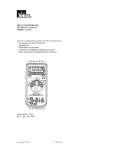
MODEL 61-791
The Service Information provides the following:
• This is a Supplemental Manual to Megger’s DM220 Service Manual and is intended for
Performance test and Calibration requirements only.
• Precautions and safety information
• Specifications
• Performance test procedure
• Calibration and calibration adjustment procedure
• Basic maintenance (replacing the battery and fuses)
Form number: TM61791-Supplement
Revision: 1. Date: August 2004
Form number TM61791-Supplement
Rev 1 Aug 2004
TABLE OF CONTENTS
Page #
Title
Introduction
1
Precautions and Safety Information
1
Safety Information
1
Performance Verification
2
Table 1 Verification 61-791
2
Calibration
3
Replacing the Battery
4
Replacing Fuses
4
Form number TM61791-Supplement
Rev 1 Aug 2004
Page 1
Introduction
Warning
To avoid shock or injury, do not perform the verification tests or calibration
procedures described in this manual unless you are qualified to do so.
The information provided in this document is for the use of qualified personnel
only.
Caution
The 61-791 contains parts that can be damaged by static discharge.
Follow the standard practices for handling static sensitive devices.
For additional information about IDEAL INDUSTRIES and its products,
and services, visit IDEAL INDUSTRIES web site at:
www.idealindustries.com
SAFETY
Review the following safety precautions to avoid injury and prevent damage to this product or any
products connected to it. To avoid potential hazards, use the product only as specified.
It is recommended that you read through the Operation or User manual before starting. Not all Caution,
Warning, or Danger precautions are listed in this manual.
CAUTION.
These statements identify conditions or practices that could result in damage to the equipment or other
property.
WARNING.
These statements identify conditions or practices that could result in personal injury or loss of life.
Specific precautions
Use proper Fuse. To avoid fire hazard, use only the fuse type and rating specified for this product.
Do not operate without covers. To avoid personal injury, do not apply any voltage or current to the
product without the covers in place.
Electric overload. Never apply a voltage to a connector on the product that is outside the range specified
for that connector.
Avoid electric shock. To avoid injury or loss of life, do not connect or disconnect probes or test leads
while they are connected to a voltage source.
Avoid electric shock. To avoid injury or loss of life, do not come in contact with tested material or probes
while the Test Button is pressed. High Voltage potentials are present during Insulation Tests..
Do not operate in wet/damp conditions. To avoid electric shock, do not operate this product in wet or
damp conditions.
Form number TM61791-Supplement
Rev 1 Aug 2004
Page 2
PERFORMANCE VERIFICATIONS
Perform the following analysis, if the meter conforms to the limits listed in Table 1 the meter is functioning
correctly. If the meter does not conform to any of the listed limits, the calibration procedure must be
performed.
Performance Verification Preparation
Set-up requirements:
1. Prepare all required equipment and standards prior to test
2. The Test Button is only needed for insulation test or to ZERO lead resistance
3. Remove bottom cover and using a calibrated meter to ensure the battery measures 8.0V ±1 V
If battery voltage is <8V, replace batteries before beginning.
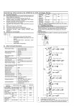
4. Simulated test leads with a value of 0.1Ω ± 10mΩ is required for Calibration of Ω/Zero Function
** Due to auto-ranging circuit thresholds, either one or no digits may appear after the decimal place on the
100MΩ test; Example { “98” or “98.2”} may be displayed.
Check safety related VR37 resistors for correct type
Check fuse is 500mA (type F) 10KA rated
Check case, leads, display and etc, for any defects.
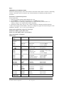
Table 1 Performance Verification
Model 61-791
Function Setting
/Range
Default
Voltmeter
Ω/Zero
Ω/Zero
Ω/Zero
Continuity
Resistance
Ω/Zero
Ω/Zero
Ω/Zero
Ω/Zero
Ω/Zero
Ω/Zero
Ω/Zero
Insulation
MΩ, 250V
MΩ, 500V
MΩ 1000V
Check on each
Voltage range
MΩ, 250V
MΩ, 500V
MΩ 1000V
Check on each
Voltage range
Apply
Reading
Specification
240V AC
240V DC
50V AC
238 to 242
226 to 254
46 to 54
[± 1% ±0 digits]
[± 1% ±10 digits]
[± 2% ±3 digits]
1Ω
Buzzer sounds
Not specified
Simulated leads
0Ω
9Ω
12Ω
90Ω
90Ω
1Ω
.08 to .12
-0.02 to +0.02
8.72 to 9.28
11.3 to 12.7
85.4 to 94.6
20.2mA to 25.8mA
202mA to 258mA
[±0.02Ω + 0.05 per lead]
[±0.02Ω]
[± 3% ±1 digits]
[± 5% ±1 digits]
[± 5% ±1 digits]
Source check
Source check
500kΩ
500kΩ
1MΩ
100kΩ
1MΩ
9MΩ
100MΩ
500MΩ
500MΩ
500MΩ
500MΩ
0MΩ
>255Vdc
>503Vdc
>1005Vdc
0.08 to 0.12
0.97 to 1.03
8.77to 9.23
95.5 to 105
360 to 640
<323V
<645V
<1290V
1.3mA to 1.95mA
Source Check
Source Check
Source Check
Not specified
[2.5%]
[2.5%]
[4.5%]
[28%]
Source Check
Source Check
Source Check
Source Check
Form number TM61791-Supplement
Rev 1 Aug 2004
Page 3
CALIBRATION
Calibration Preparation
Required Equipment
The class of calibrator or equipment should have an accuracy that exceeds, by an expectable ratio, the
accuracy of the instrument under test.
Required fixed resistors: 0Ω, 9Ω, 12Ω,, 90Ω, 500KΩ, 8MΩ, 100MΩ
Simulated Test leads. With a total resistance of <.1Ω ±10mΩ or .05Ω per simulated lead.
Calibration Procedure
It is recommended that all IDEAL meters undergo calibration checkup on an annual bases.
61-791 Calibration Procedure.
Calibration
Voltage Set-up
1) Set the Function/Range Switch to the “Ω” position.
2) Set the output of the AC calibrator for 240V and connect it to the “+” and “─” input terminals.
3) Adjust [V] R30 until the display reads 240V ± 1 digit.
4) Apply 240V DC and Check for a display of 240V ± 10 digit
Note: Meter will beep while Voltage is present.
Voltage sourcing test and [M Ω] adjustment
5) Set the Function/Range Switch to MΩ 500V
6) Apply a 500KΩ Load to unit, measured Vdc across load should be >504V
7) Apply a 100MΩ Load to unit, measured Vdc across load should be >640V
8) Apply an 8MΩ Standard Load to unit
9) Adjust [MΩ], R100 for a reading of 8.00MΩ ± 5 digits
Ohms Zero Adjustment:
1) Place unit in the Ω/Zero function.
2) Connect the Simulated test leads to unit
3) Adjust [0Ω], R159 for a reading of 0.10Ω
4) Press button to set reading to zero
5) Confirm 0.00 ±3 digits
Ohms Adjustment,
1) Place unit in the Ω/Zero function.
2) Connect a 9Ω standard to unit
3) Adjust [Ω], R61 for a reading of 9Ω ±3 digits
a. Connect 12Ω check reading is between11.6Ω to 12.4Ω
b. Connect 90Ω check reading is between 86.0Ω to 94.0Ω
Buzz check
(continuity} position.
• Place unit in the
• Short test leads and confirm buzzer operation.
Form number TM61791-Supplement
Rev 1 Aug 2004
Page 4
Battery Replacement
1. Disconnect the test leads from any circuit under test and turn off meter.
2. Release screw from the bottom end of case cover. ( Screw is secured to case)
3. Remove the 6 AA batteries from battery adapter.
4. Install new 6 new AA batteries into adapter, observing proper polarity of battery.
(Alkaline batteries are recommended.)
6. Install bottom case cover and secure with screws.
Replacing Fuse
1. Disconnect the test leads and turn the range switch to “OFF”.
2. Release screw from the bottom end of case cover. ( Screw is secured to case)
3. Check fuse with a digital multimeter with a source current < 10mA in low resistance range.
Replace fuse with a 500 mA (type F), 10KA rated fuse.
4. Install bottom cover and secure with screw.
Form number TM61791-Supplement
Rev 1 Aug 2004