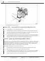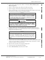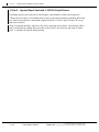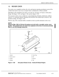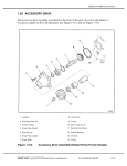
1
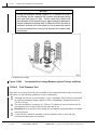
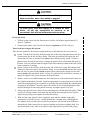
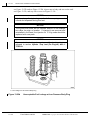
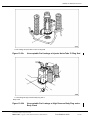
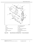
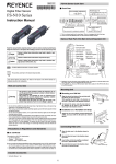
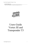
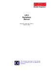
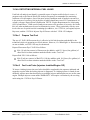
SERIES 60 SERVICE MANUAL
13.14A DETECTING INTERNAL FUEL LEAKS
Used lube oil analysis can identify a potential source of engine trouble before it occurs. A
program such as the Detroit Diesel Oil Analysis Program is recommended for monitoring
crankcase oil in all engines. One of the most serious conditions used oil analysis can uncover
is the presence of excessive fuel in the lube oil which should not exceed 2.5% maximum of oil
volume, reference Detroit Diesel’s Publication 7SE270 “Engine Requirements for Lubricating
Oil, Fuel and Filters.” While used oil analysis can uncover the presence of excessive fuel in the
lube oil, other methods must be used to determine its source. Three particularly effective tests
involve the use of special test fuel containing dye additives , the J 37050-A, (on engine) Injector
Pop tester, and the J 34760-A Injector Pop-N-Fixture with the J 34760-147A adaptor.
13.14a.1
Prepare Test Fuel
The use of J 28431-B Fluorescent dye is effective in fuel leak detection and should be the
technician's choice in preparing a test fuel mixture. However, if a “Black light“ or fluorescent dye
are not available, red LTO 1140 may be substituted.
Prepare Fluorescent Dye J 28431-B as follows:
Mix 118 ml (four ounces) of fluorescent dye additive with 15.1 liters (four gallons) of
diesel fuel in a clean container marked with the words “Test Fuel”.
Prepare Red LTO 1140 as follows:
Mix 59 ml (two ounces) of Red LTO 1140 dye additive with 18.9 liters (five gallons) of
diesel fuel in a clean container marked with the words “Test Fuel”.
13.14a.2
Fuel Leak Tests (Injectors Installed/Engine Off)
To locate a leaking injector the tests below should be completed in the sequence indicated and
stopped at a point when the leaking injector is diagnosed. If a leaking injector is found, do not
arbitrarily replace more than that injector, as multiple injector malfunctions are rare on the same
engine. Multiple injector returns under WARRANTY will require verification by the servicing
outlet using the J 34760-A Pop-N-Fixture.
All information subject to change without notice.
6SE483 0303 Copyright © 2003 DETROIT DIESEL CORPORATION
From Bulletin 6-60-03
13-78a
13.14A
DETECTING INTERNAL FUEL LEAKS
NOTICE:
During fuel pressure testing (engine off, 5 minutes at 50 psi)
fuel leakage will be evident at the injector body/plunger spring
seat area see Figure 13-22a. Factory tests have shown that
accumulation of fuel at each injector, approximately a tablespoon
may be evident during these tests. Evidence of fuel in this area is
expected, as there is no other place for it to go when the injector
cavities are pressurized, forcing fuel between the injector body
and plunger.
1. Acceptable Fuel Leakage
Figure 13-22a
13.14a.3
Acceptable-Fuel Leakage Between injector Plunger and Body
Fuel Pressure Test
Since there is no known fuel leak tester available in the commercial market today, one must be
fabricated. Use the following guidelines to help in fabricating:
Although test fuel can be pressurized by variety of methods, Detroit Diesel recommends
an air/fuel accumulator design capable of safely withstanding a minimum pressure of
345 kPA (50 psi).
The tester should have a capacity of 9.5 liters (2.5 gallons) of test fuel and provide for
contamination free storage of the test fuel when not in use.
Regulated shop air may be used to charge the accumulator tank and maintain a constant
test fuel pressure.
A shut-off valve should be installed at the accumulator outlet to start and stop
pressurization during the test sequence.
All information subject to change without notice.
13-78b
From Bulletin 6-60-03
6SE483 0303 Copyright © 2003 DETROIT DIESEL CORPORATION
SERIES 60 SERVICE MANUAL
To avoid injury from the sudden release of a high-pressure
hose connection, wear a face shield or goggles.
To avoid injury from tank rupture or a sudden air hose
failure, do not use unregulated air pressure or an
accumulator tank with an inadequate pressure rating.
Fuel Leak Tester
1. Fill fuel system tester with the fluorescent or red dye fuel mixture approximately 9.5
liters (2.5 gallons).
2. Charge tester (outlet valve closed) with shop air regulated at 345 kPA (50 psi) .
Tester hook-up to engine fuel system.
There are two options for fuel tester to engine hook-up as determined by the ease of access.
Option 1–Remove the fuel line from the outlet side of the fuel pump and connect the fuel
system testers line in this fuel hose fitting. This hook-up location will require the fuel
system shut-off valve to remain in the open position during testing. About 3.8 liters (1
gallon) of test fuel will be necessary to charge the engine's fuel system from this hook-up
location. Test fuel will not harm the engine's fuel filters and may remain in the fuel system
at the conclusion of testing.
Option 2–Remove the fuel line from the outlet side of the fuel by-pass filter adapter and
connect the fuel testers line in this fuel hose fitting. It is recommended that the fuel system
shut-off valve be placed in the closed position before removing the engine fuel line and
remain closed until reinstalled. About 1.9 liter (0.5 gallon) of test fuel will be necessary to
charge the engine's fuel system from this hook-up location.
3. Remove rocker cover and disconnect the fuel outlet line at a convenient location between
the cylinder head and the fuel tank. Install an appropriate size pipe plug (loose) in the fuel
outlet line end and place it in a container to catch the fuel while priming the cylinder head.
If equipped, Jake Brakes® should be removed to allow for the visual examination of the
injectors during fuel leak testing and if necessary on-engine injector ’Pop’ test.
4. Slowly open the fuel tester’s shut-off valve and charge the cylinder head fuel galley. When
test fuel is flowing from the fuel return line and air has been purged from the system,
tighten the pipe plug at the engine fuel outlet line fitting.
5. With the fuel tester shut-off valve completely open and the cylinder head galley
pressurized to 345 kPa (50 psi), visually monitor the overhead using a black light for
five minutes if the test time goes beyond five minutes it will become more difficult to
determine the faulty injector due to expected leakage at the injector plunger/body. Pay
special attention to any leaks at the injector body, high and low pressure body plugs,
All information subject to change without notice.
6SE483 0303 Copyright © 2003 DETROIT DIESEL CORPORATION
From Bulletin 6-60-03
13-78c
13.14A
DETECTING INTERNAL FUEL LEAKS
see Figure 13-22b and see Figure 13-22d, injector nut to body and nut to tube seals
see Figure 13-22c, and stop valve cover see Figure 13-22e.
NOTICE:
Injector plunger/body leakage at the follower spring area is
normal and expected during this test.
NOTICE:
The figures that follow do not illustrate amount of fuel leakage
but rather its origin or location. If injector(s) are removed and
reinstalled in the head, the injector nut ’O’ ring seals should be
replaced with new parts.
NOTICE:
If pressurization testing does not reveal the leaking injector,
proceed to section Injector ’Pop’ test (On Engine) with J
37050-A.
1. Fuel Leakage at Low Pressure Body Plug
Figure 13-22b
Unacceptable-Fuel Leakage at Low Pressure Body Plug
All information subject to change without notice.
13-78d
From Bulletin 6-60-03
6SE483 0303 Copyright © 2003 DETROIT DIESEL CORPORATION
SERIES 60 SERVICE MANUAL
1. Fuel Leakage at Injector Nut-to-Tube ’O’ Ring Seal
Figure 13-22c
Unacceptable-Fuel Leakage at Injector Nut-toTube ’O’ Ring Seal
1. Fuel Leakage at High Pressure Body Plug and or
Body Crack
Figure 13-22d
Unacceptable-Fuel Leakage at High Pressure Body Plug and or
Body Crack
All information subject to change without notice.
6SE483 0303 Copyright © 2003 DETROIT DIESEL CORPORATION
From Bulletin 6-60-03
13-78e
13.14A
DETECTING INTERNAL FUEL LEAKS
1. Fuel Leakage at Injector Stop Valve Cover
Figure 13-22e
Unacceptable-Fuel Leakage at Injector Stop Valve Cover
6. Correct the cause of any abnormal fuel leaks.
7. Bleed the pressure from the accumulator tank and remove the pipe plug from the fuel
outlet line. Reinstall the fuel outlet line in the engine’s fuel system. Disconnect the fuel
tester and reinstall the fuel inlet line in the engine’s fuel system.
8. Completely open the engine’s fuel shut-off valve and assure that all fuel connections are
tight. Reinstall the rocker cover and start engine to purge the air from the fuel system. If
the engine fails to start, it may be necessary to prime the fuel system.
13.14a.4
Injector ’Pop Test (On Engine) With J 37050-A
Perform this test if injector leakage cannot be identified after pressure testing the cylinder head.
Energizing and stoking the suspect injector(s) will produce the internal fuel pressures created
during engine operation, thus increasing any abnormal fuel leakage. Refer to manufacture’s
instructions supplied with the J 37050-A tester for set-up procedure.
Perform the following steps for the Injector Pop Test.
1. Wipe down the overhead to remove any test fuel generated from previous testing.
2. Disconnect both 5-way injector harness connectors at the ECM.
3. Connect alligator clips from the tester cable to the EUI. It is not necessary to disconnect
the solenoid terminal leads from the EUI engine wiring harness if the 5-way injector
harness connectors have been removed from the ECM.
All information subject to change without notice.
13-78f
From Bulletin 6-60-03
6SE483 0303 Copyright © 2003 DETROIT DIESEL CORPORATION
SERIES 60 SERVICE MANUAL
4. Connect power supply clips to the vehicles 12 volt battery. Red to Positive(+) and
Black to Negative(-).
5. Option 1–Connect remote starter cable to the vehicle starter motor.
6. Option 2–Operate vehicle starter switch from drivers seat in the cab.
7. Depress and hold trigger on tester's pistol grip start button while rotating 'current' control
knob clockwise to increase current to the injector solenoid.
NOTICE:
The Letter ’O’ at the left side of the LED amps readout window
indicates the injector solenoid is OPEN, ’C’ indicates CLOSED.
The pistol grip trigger must be released and depressed for each
time the injector solenoid is activated.
To avoid injury before starting and running the engine,
ensure the vehicle is parked on a level surface, parking
brake is set, and the wheels are blocked.
8. Using the vehicle starter, motor the engine while energizing the injector solenoid. It
should only be necessary to cycle the solenoid once or twice to pressurize the injector.
Energize only one injector at a time.
NOTICE:
While activating the injector solenoid, cylinder detonation may
occur when motoring the engine. This occurrence will not harm
the engine. It should be noted again that if the 5-way injector
connectors are not disconnected at the ECM, the engine may
start.
9. With the vehicle start switch in the OFF position or remote starter cable disabled, visually
examine each suspect injector for abnormal fuel leakage using a “black light” or look for
evidence of red dye if LTO test fuel is used.
10. Repeat the above procedure for each injector being tested.
11. Correct the cause of any abnormal fuel leakage.
12. Refer to Fuel Leak Tester, instruction items 7 and 8.
All information subject to change without notice.
6SE483 0303 Copyright © 2003 DETROIT DIESEL CORPORATION
From Bulletin 6-60-03
13-78g
13.14A
DETECTING INTERNAL FUEL LEAKS
13.14a.5
Injector Bench Test with J 34760-A Pop-N-Fixture
If multiple injectors are removed for fuel leakage, each should be bench tested using the J
34760-A Pop-N-Fixture. Fuel leakage may be more easily observed while performing this bench
test. Refer to manufacture’s instructions supplied with the J 34760-A Pop-N-Fixture for set-up
and test procedures.
Wash, wipe down and allow injector to dry before mounting in test fixture. Fuel leakage will be
more recognizable by adding fluorescent dye to the fixture’s fuel reservoir and using a “black
light” to examine the injector during testing.
All information subject to change without notice.
13-78h
From Bulletin 6-60-03
6SE483 0303 Copyright © 2003 DETROIT DIESEL CORPORATION