1
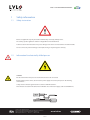
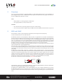
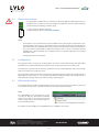
LVLØ – KNX INTEGRATION MANUAL
www.lvl0.eu
LVLØ – KNX INTEGRATION MANUAL
Contents
1
Safety information
4
1.1
Safety instructions
4
1.2
Information for electrically skilled persons
4
Overview
5
2
3
KNX (Konnex) and LVLØ
5
3.1
Electrical connection
6
3.2
Configuration
6
3.3
KNX network address
6
Engineering with ETS
7
KNX Group Addresses
7
4
4.1
4.1.1 10/0/x Communication objects for Home screen and statistics section
8
4.1.2 10/1/x Communication objects for Dashboard section
8
4.1.3 10/2/x Communication objects for Settings and Service section
9
4.2
Example communication
10
4.2.1 1-bit output control
11
4.2.2 2-byte write and display value
11
4.2.3 2-byte display status
11
5
EC Declaration of Conformity
12
6
Notes
13
© ISA, s.r.o. 2015. All rights reserved.
We reserve the right to change the specification without prior notification.
Always check for new version of this document@ www.lvl0.eu
KNX integration manual 1.0 | Feb-2015 | LM0003-1.0EN www.lvl0.eu
2 of 13
LVLØ – KNX INTEGRATION MANUAL
1
Safety information
1.1
Safety instruction
Electrical equipment may only be installed and fitted by electrically skilled persons.
The country specific regulations and the valid guidelines must be followed.
Failure to observe the instructions may cause damage to the device and result in fire and other hazards.
Do not connect any external voltage to the inputs. Doing so may damage the device(s).
1.2
Information for electrically skilled person
DANGER!
Electrical shock when live parts are touched. Electrical shocks can be fatal.
Before working on the device, disconnect the power supply and cover up live parts in the working
environment.
Safety clearance must be guaranteed in accordance with IEC 60664--1.
There must be at least 4 mm between the individual cores of the 230 V supply cable and the KNX line.
© ISA, s.r.o. 2015. All rights reserved.
We reserve the right to change the specification without prior notification.
Always check for new version of this document@ www.lvl0.eu
KNX integration manual 1.0 | Feb-2015 | LM0003-1.0EN www.lvl0.eu
3 of 13
LVLØ – KNX INTEGRATION MANUAL
2Overview
You can use these instructions to integrate LVLØ to an existing KNX network and to create visualization of
pool equipped with this device. LVLØ communication objects are divided into three groups. This division is
based on LVLØ mobile application concept.
NOTE:
•
•
Group addresses are managed by the manufacturer.
No. of group addresses and associations is 52.
WARNING:
•
•
3
This document does not provide guidance for device commissioning.
It is necessary to perform complete setup of LVLØ to ensure that LVLØ controller will work as expected.
KNX and LVLØ
This document contains specific information applicable to the European Tool Set (ETS) only.
S-mode communications are not dealt with here.
The KNX Association has its headquarters in Brussels and is an organization or association of manufacturers
which maintains the KNX standard and develops it further. The KNX Association supports the trend towards
the “smart home”, in which the various building services including lighting, heating, security systems and
other - all communicate on the same network. Building control technology as provided by KNX is a specialized
form of automated process control, dedicated to the needs of home and building applications. One premise
for KNX is to furnish a radically decentralized, distributed approach; hence the term network
The KNX bus enables the LVLØ to communicate with each other, i.e. to exchange process values and system
data in LTE mode (LTE = Logical Tag Extended).
LTE mode (LTE = Logical Tag Extended) is characterized by the assignment of zone addresses (logical tags)
to create communications bindings for the exchange of process values. Device with the same zone address
exchange process values with each other, one zone address being capable of transmitting the values of many
data points.
The KNX bus used with LVLØ is referred to as “KNX TP1”. A full-scale KNX network is a three-level structure
consisting of one area line, from which 15 main lines branch off. A further 15 lines can branch off from each
main line. A network consisting of main lines and lines requires area and line couplers. If no area and line
couplers are used, the network is restricted to one line. Permissible bus topologies are tree, line and star
topologies. These topologies can be mixed as required. However, ring topologies are not allowed. The tree
topology has advantages over other topologies in cases where a large network has to be created.
The bus cable comprises two twisted conductors, CE+ (red) and CE– (black).
Unshielded bus cables are permitted for the KNX bus in conjunction with LVLØ device. However shielded bus
cables are recommended, if high interference is anticipated.
The KNX bus uses CSMA/CA (CSMA = Carrier Sense Multiple Access / CA = Collision Avoidance) to access the
bus. With this method of access every bus user has equal data transmission rights. There is no communication
master (in contrast to the master/slave principle). The data is exchanged directly (peer-to-peer) between bus
users.
© ISA, s.r.o. 2015. All rights reserved.
We reserve the right to change the specification without prior notification.
Always check for new version of this document@ www.lvl0.eu
KNX integration manual 1.0 | Feb-2015 | LM0003-1.0EN www.lvl0.eu
4 of 13
LVLØ – KNX INTEGRATION MANUAL
3.1
Electrical connection
To enable KNX on LVLØ, connect a Twisted Pair cable which fulfils the KNX requirements (e.g.
YCYM 2×2×0.8 or J-Y(St)Y 2×2×0.8 in TP1 design) to the KNX bus connector. When installing a
standard cable, the following conditions apply:
+ (plus) – Red wire - (GND) – Black wire
For detailed specification refer to SERVICE MANUAL.
NOTE:
•
Insulated wire cores of sheathed mains cables and KNX TP1 bus cables may be installed next to each
other without any clearance space. A minimum clearance space of 4 mm must be observed between
the insulated wire cores of KNX TP1 bus cables and those of sheathed mains cables. Alternatively, the
wire cores must be provided with an equivalent insulation, such as a spacer or insulation sleeving
(DIN VDE 0110-1, Basic insulation). This also applies to wire cores of other cables that are not part of
SELV/PELV circuits.
•
Terminating resistor is not required.
3.2Configuration
This application offers a wide range of setting options in order to execute numerous functions with a KNX
pushbutton and controlled KNX devices like touch panels, etc. Or use pool functions in KNX scenes.
You will find an overview of all the functions, parameters and the related adjustable values in the “Group
addresses parameters and settings „section.
All 1-bit writable communication objects need to be triggered by 1 bit pulse edge function (send telegram 1
following by 0). If pulse edge “1” / ”0” is detected at the input communication object, the output reacts to it
immediately by changing current state and by sending a status telegram.
3.3
KNX network address
The network address for a full-scale KNX network consists of the area, line and device address. It reflects the
exact position of a bus device in the overall network and is unique within the network.
NOTE:
The LVLØ Ultimate Pool Controller bus device
is factory-set with the KNX defined individual
address 1.1.222 and can be changed only via ISA
remote support. Please make sure this address is
not used in KNX network.
ETS software used for LVLØ is present by KNX Bus Access and Object Server in ETS.
© ISA, s.r.o. 2015. All rights reserved.
We reserve the right to change the specification without prior notification.
Always check for new version of this document@ www.lvl0.eu
KNX integration manual 1.0 | Feb-2015 | LM0003-1.0EN www.lvl0.eu
5 of 13
LVLØ – KNX INTEGRATION MANUAL
4
Engineering with ETS
4.1
KNX Group Addresses
Communication between devices in an installation is carried out via group addresses.
The group addresses are already assigned to the group objects. When using the ETS engineering tool, e.g.
in systems with third-party devices, the ETS project database of LVLØ device must be imported into ETS.
Selected data points of the LVLØ device can communicate also in S-Mode.
You can download ETS files from www.lvl0.eu/download/.
NOTE:
Pay special attention to the following design when engineering with ETS:
•
Fixed group addresses are defined in the KNX standard for all system functions.
•
Group address are set in the LVLØ bus devices before they leave the factory.
•
Main group 10, middle group 0 is used for LVLØ application Home screen functions. Contains
all major functions and information’s to operate pool equipment like light, cover, auxiliaries and
read measured values of water quality and temperature.
•
Main group 10, middle group 1 is used for LVLØ application Dashboard features. Contains all
major information’s about condition of pool and pool equipment. Current state of circuit breakers,
sensors, buffer tank, etc.
•
Main group 10, middle group 2 is used for LVLØ application Setting functions. Contains
all major functions to control filtration, heating, cooling details about current LVLØ and pool
conditions. Status of circuit breakers, pump and valves status, sensor alerts etc.
© ISA, s.r.o. 2015. All rights reserved.
We reserve the right to change the specification without prior notification.
Always check for new version of this document@ www.lvl0.eu
KNX integration manual 1.0 | Feb-2015 | LM0003-1.0EN www.lvl0.eu
6 of 13
LVLØ – KNX INTEGRATION MANUAL
4.1.1 10/0/x Communication objects for Home screen and statistics section
Group
Address
Data Point Name
Data Point Type
Description
10/0/0
LVL0 Water Temperature Output °C
display of value EIS5
2 Byte
R
9.001
Display actual water temperature.
Floating value (°C), cyclically send to bus.
10/0/1
LVL0 Outside temperature Input °C
control EIS5
2 Byte
W
9.001
Control outside temperature from KNX
Floating value (°C).
NOTE: Setting via LVLØ mobile app must Settings>Service>HEATING>outside temperature source is set
to “KNX” option.
10/0/2
LVL0 Outside Temperature Output °C
display of value EIS5
2 Byte
R
9.001
Display actual outside temperature.
Floating value (°C), cyclically send to bus.
10/0/3
LVL0 Light Control (Send 1/0)
control pulse edge 1/0
1 bit
W
1.001
Actuator to control “LIGHT” output. Toggle current
output status when pulse edge telegram (0/1) will be
received on this input. Status feedback will be send
when output changes state.
10/0/4
LVL0 Light Status Feedback (1=On, 0=Off )
display of status
1 bit
R
1.001
Status feedback of “LIGHT” output.
10/0/5
LVL0 Pool Cover Control - Open (Send 1/0)
control pulse edge 1/0
1 bit
W
1.001
Actuator to control “POOL COVER” output. Pool cover
will open when pulse edge (0/1) telegram will be
received on this input.
10/0/6
LVL0 Pool Cover Control - Close (Send 1/0)
control pulse edge 1/0
1 bit
W
1.001
Actuator to control “POOL COVER” output. Pool cover
will close when pulse edge (0/1) telegram will be
received on this input.
10/0/7
LVL0 Pool Cover Status Feedback (1=Open,
0=Closed)
display of status
1 bit
R
1.001
Status feedback of “POOL COVER” output is send to
bus when the output change state. Feedback is send
cyclically to bus every 600s.
10/0/8
LVL0 AUX1 Control (Send 1/0)
control pulse edge 1/0
1 bit
W
1.001
Actuator to control “AUX1” output. Toggle current
output status when pulse edge telegram (0/1) will be
received on this input. Status feedback will be send
when output changes state.
10/0/9
LVL0 AUX1 Status Feedback (1=On, 0=Off )
display of status
1 bit
R
1.001
Status feedback of "AUX1" output.
10/0/10
LVL0 AUX2 Control (Send 1/0)
control pulse edge 1/0
1 bit
W
1.001
Actuator to control "AUX2" output. Toggle current
output status when pulse edge telegram (0/1) will be
received on this input. Status feedback will be send
when output changes state.
10/0/11
LVL0 AUX2 Status Feedback (1=On, 0=Off )
display of status
1 bit
R
1.001
Status feedback of "AUX2" output.
10/0/12
LVL0 Current Actual pH Output
display of value EIS5
2 Byte
R
9.*
Display actual pH value.
Floating value is send to bus on change or cyclically
based on parameter 10/2/15.
10/0/13
LVL0 Current Actual Redox Output mV
display of value EIS5
2 Byte
R
9.020
Display actual Redox/ORP value in mV (-2000 +2000).
Value is send to bus on change or cyclically based on
parameter 10/2/15.
10/0/14
LVL0 Current Actual Free Chlorine Output mg/l
display of value EIS5
2 Byte
R
9.*
Display actual CLF (Free chlorine) value in mg/l (ppm).
Floating value is send to bus on change or cyclically
based on parameter 10/2/15.
10/0/15
LVL0 Current External System Temperature
Output °C
display of value EIS5
2 Byte
R
9.001
Display actual temperature of external heating/cooling
system. Floating value (°C) is cyclically send to bus.
© ISA, s.r.o. 2015. All rights reserved.
We reserve the right to change the specification without prior notification.
Always check for new version of this document@ www.lvl0.eu
KNX integration manual 1.0 | Feb-2015 | LM0003-1.0EN www.lvl0.eu
7 of 13
LVLØ – KNX INTEGRATION MANUAL
4.1.2 10/1/x Communication objects for Dashboard section
Group
Address
10/1/0
10/1/1
10/1/2
10/1/3
Data Point Name
LVL0 Service Required Status Feedback
(1=Required, 0=OK)
LVL0 Service Area Status Feedback (0=OK,
1,2,4=Err)
LVL0 Circuit Breakers Status Feedback (0=OK,
1,2,4=Err)
LVL0 Water Treatment Status Feedback
10/1/4
LVL0 Pump and Valves Status Feedback
10/1/5
LVL0 Buffer Tank Max.Make Up Time Status
Feedback (1=ERR, 0=OK)
10/1/6
10/1/7
10/1/8
10/1/9
LVL0 Buffer Tank Max.Make Up Time Reset
(Send 1/0)
LVL0 Buffer Tank Water Level Status Feedback
LVL0 Buffer Tank Safety Status Feedback
LVL0 Sensors Status Feedback
Data Point Type
display of status
1 bit
display of value EIS5
2 Byte
display of value EIS5
2 Byte
display of value EIS5
2 Byte
Description
R
R
R
R
1.001
Summarized status feedback object to display if service
intervention on pool is required. Telegram is send
cyclically to bus every 600s.
7.*
Summarized status feedback object to display service
code in case of service is required on pool. Telegram
with code is send to bus cyclically every 600s. Code
explanation:
1 - water quality long-term (OK/ERR)
2 - technology (OK/ERR)
4 - service intervals (OK/ERR)
7.*
Summarized status feedback object to display exact
service code in case of Circuit breakers failure. Telegram
with code is send to bus cyclically every 600s. Code
explanation:
1 - dosing breaker failure (OK/ERR)
2 - filtration breaker failure (OK/ERR)
4 - additional technology breaker failure (OK/ERR)
7.*
Summarized status feedback object to display exact
service code in case of water treatment issues. Telegram
with code is send to bus cyclically every 600s. Code
explanation:
1 - pH (OK/ERR)
2 - ORP/CLF (OK/ERR)
4 - chemical stocks (OK/ERR)
8 - electrodes (OK/ERR)
display of value EIS9
2 Byte
R
7.*
Display actual status of outputs for “DOSING PUMPS 1
- 4”, “FILTRATION”, “3 WAY VALVE” and “MAKE UP WATER
VALVE”. Summarized status telegram is send to bus on
change and cyclically every 600s. Code explanation:
1 - filtration pump (ACTIVE/INACTIVE)
2 - dosing pump 1 (ACTIVE/INACTIVE)
4 - dosing pump 2 (ACTIVE/INACTIVE)
8 - dosing pump 3 (ACTIVE/INACTIVE)
16 - dosing pump 4 (ACTIVE/INACTIVE)
32 - heating valve (OPEN/CLOSE)
64 - make up water (OPEN/CLOSE)
display of status
1 bit
R
1.005
Status to display issue with filling valve. If max. Make
up water safety time is reached, alarm telegram is
triggered. Telegram is send cyclically to the bus every
600s.
1.001
Actuator to reset, confirm “Max. Make up time” issue.
When pulse edge (0/1) telegram will be received on
this input, make up water valve will be again enabled
after reaching max. Make up time set by LVLØ mobile
application. Counter of make-up water duration will be
reset to 0.
7.*
Display actual water level in buffer tank, based on
setting in LVLØ mobile application. H1 is on top of the
tank, H4 represent the lowest level. Telegram with code
is send to bus cyclically every 600s. Exact status codes:
1 - buffer tank (actual utilization) - H1
2 - buffer tank (actual utilization) - H2
4 - buffer tank (actual utilization) - H3
8 - buffer tank (actual utilization) - H4
8.*
Display safety messages when processing water in
buffer tank. Telegram with code is send to bus cyclically
every 600s. Message codes:
1 - dry run protection (ACTIVE/INACTIVE)
2 - forced pumping (ACTIVE/INACTIVE)
4 - make up water (ACTIVE/INACTIVE)
8.*
Summarized status feedback object to display sensors
status feedback messages. Telegram with code is send
to bus cyclically every 600s. Code explanation:
1 - water temperature sensor (OK/ERR)
2 - outside temperature sensor (OK/ERR)
4 - ext. system temperature sensor (OK/ERR)
8 - pH electrode (OK/ERR)
16 - ORP electrode (OK/ERR)
control pulse edge 1/0
display of value EIS5
display of value EIS9
display of value EIS5
1 bit
2 Byte
2 Byte
2 Byte
© ISA, s.r.o. 2015. All rights reserved.
We reserve the right to change the specification without prior notification.
Always check for new version of this document@ www.lvl0.eu
KNX integration manual 1.0 | Feb-2015 | LM0003-1.0EN W
R
R
R
www.lvl0.eu
8 of 13
LVLØ – KNX INTEGRATION MANUAL
Group
Address
Data Point Name
Data Point Type
Description
10/1/10
LVL0 Regular Service in Day Status Feedback
display of value EIS9
4 Byte
R
14.*
Display days until next regular service, set via LVLØ
mobile app. Telegram with value cyclically send to bus
every 600s.
10/1/11
LVL0 pH Electrode Service in Day Status
Feedback
display of value EIS9
4 Byte
R
14.*
Display days until next service on pH electrode
(calibration, replacement), set via LVLØ mobile app.
Telegram with value cyclically send to bus every 600s.
10/1/12
LVL0 Redox Electrode Service in Day Status
Feedback
display of value EIS9
4 Byte
R
14.*
Display days until next service on Redox electrode
(calibration, replacement), set via LVLØ mobile app.
Telegram with value cyclically send to bus every 600s.
10/1/13
LVL0 CLF Electrode Service in Day Status
Feedback
display of value EIS9
4 Byte
R
14.*
Display days until next service on Free chlorine electrode
(calibration, replacement), set via LVLØ mobile app.
Telegram with value cyclically send to bus every 600s.
10/1/14
LVL0 UV Lamp Service in Hours Status
Feedback
display of value EIS9
4 Byte
R
14.*
Display hours until UV Lamp replacement, set via LVLØ
mobile app.
Telegram with value cyclically send to bus every 600s.
10/1/15
LVL0 Ozone Generator Service in Day Status
Feedback
display of value EIS9
4 Byte
R
14.*
Display days until next service on ozone generator, set
via LVLØ mobile app.
Telegram with value cyclically send to bus every 600s.
10/1/16
LVL0 Salt Chlorine Gen. Service in Day Status
Feedback
display of value EIS9
4 Byte
R
14.*
Display days until next service of salt chlorine generator,
set via LVLØ mobile app.
Telegram with value cyclically send to bus every 600s.
10/1/17
LVL0 Filtration Service in Day Status Feedback
display of value EIS9
4 Byte
R
14.*
Display days until next service on filtration unit (filter),
set via LVLØ mobile app.
Telegram with value cyclically send to bus every 600s.
10/1/18
LVL0 Heat Pump Service in Day Status
Feedback
display of value EIS9
4 Byte
R
14.*
Display days until next service on heat pump or heat
exchanger, set via LVLØ mobile app.
Telegram with value cyclically send to bus every 600s.
10/1/19
LVL0 Salt Chlorine Generator Status Feedback
display of status
1 bit
R
1.005
Status to display “SALT GENERATOR” output state.
Telegram is send cyclically to the bus every 600s.
4.1.3 10/2/x Communication objects for Settings and Service section
Group
Address
Data Point Name
10/2/0
LVL0 Filtration Pump Control (Send 1/0)
10/2/1
LVL0 Filtration Pump Status Feedback
(1=On, 0=Off )
Data Point Type
Description
control pulse edge 1/0
1 bit
W
1.001
Actuator to control “FILTRATION” output. Toggle
current output state when pulse edge telegram (0/1)
will be received on this input. Status feedback will be
send when output changes state.
display of status
1 bit
R
1.001
Status feedback of “FILTRATION” output.
control pulse edge 1/0
1 bit
W
1.001
Actuator to control filter cleanup/backwash process.
Detailed backwash process can be set via service menu
of the LVLØ mobile app. To initiate/start backwash pulse
edge telegram (0/1) need to be send to this input. Status
feedback will be send when the process is running.
LVL0 Filter Cleanup Status Feedback (1=On,
0=Off )
display of status
1 bit
R
1.001
Status feedback of the filter cleanup/backwash process.
10/2/4
LVL0 Water Temperature Setpoint Input °C
control EIS5
2 Byte
W
9.001
Control water temperature set point from KNX.
Floating value (°C) will adjust desired water temperature.
10/2/5
LVL0 Water Temperature Setpoint Output
display of value EIS5
2 Byte
R
9.001
Display actual water temperature set point value.
Floating value (°C) is cyclically send to bus every 600s.
10/2/6
LVL0 Water Temperature Setpoint Hysteresis
Input °C
control EIS5
2 Byte
W
9.001
Floating value (°C). Control hysteresis of the 2-step
heating/cooling controller for water temperature
from KNX. Setting rule: Small hysteresis leads to small
fluctuations, but frequent switching. Large hysteresis
leads to big fluctuations, but infrequent switching.
10/2/7
LVL0 Water Temperature Setpoint Hysteresis
Output °C
display of value EIS5
2 Byte
R
9.001
Display actual set point hysteresis temperature.
Floating value (°C) is cyclically send to bus every 600s.
10/2/2
LVL0 Filter Cleanup Control (Send 1/0)
10/2/3
© ISA, s.r.o. 2015. All rights reserved.
We reserve the right to change the specification without prior notification.
Always check for new version of this document@ www.lvl0.eu
KNX integration manual 1.0 | Feb-2015 | LM0003-1.0EN www.lvl0.eu
9 of 13
LVLØ – KNX INTEGRATION MANUAL
Group
Address
Data Point Name
10/2/8
LVL0 Cooling Enable Control (Send 1/0)
10/2/9
LVL0 Cooling Status Feedback (0=Disabled;1=Enabled)
10/2/10
10/2/11
10/2/12
LVL0 6-Way Valve Status Feedback
1 bit
W
1.001
Actuator to enable/disable water cooling feature.
Toggle current output status when pulse edge
telegram (0/1) will be received on this input. Status
feedback will be send when output changes state.
display of status
1 bit
R
1.001
Status feedback of the cooling feature output.
control EIS5
10/2/14
LVL0 Heating Valve Control (Send 1/0)
10/2/15
LVL0 Minimum Sensors Sending Interval
Input (s)
2 Byte
display of value EIS5
LVL0 Pool Mode Control Input
LVL0 Pool Mode Control Output
Description
control pulse edge 1/0
LVL0 6-Way Valve Control Input
10/2/13
4.2
Data Point Type
2 Byte
control EIS5
2 Byte
display of value EIS5
2 Byte
control pulse edge 1/0
1 bit
control of value EIS5
2 Byte
W
R
W
R
W
7.*
Control input to switch position of “6 WAY VALVE”
outputs. To switch position, send telegram with
number of desired valve position:
1 - position closed
2 - position backwash
3 - position recirculate
4 - position waste
5 - position filter
6 - position rinse
Actual position will be send via status feedback object.
7.*
Display actual position of “6 WAY VALVE” output.
Telegram with position is send on change and cyclically
every 600s. Position values:
1 - position closed
2 - position backwash
3 - position recirculate
4 - position waste
5 - position filter
6 - position rinse
7.*
Control actual pool mode. To switch mode, send
telegram with number of desired mode:
1 - in use
2 - closed
3 - winter
NOTE: service mode can be controlled only from device
LCD panel
7.*
Display current pool mode via status feedback value.
Telegram with current mode number is send to bus on
change and cyclically every 600s.
1 - pool in use
2 - pool closed
3 - pool winter mode
4 - pool service mode
1.001
Actuator to control “3 WAY VALVE” output. Toggle
current output state (open/closed) when pulse edge
telegram (0/1) will be received on this input. Use this
input to control heating valve from master heating
system.
7.005
Control interval for sending measured values
(temperatures, CLF, pH, ORP) to bus. Applies only to
sensors.
Example communication
© ISA, s.r.o. 2014. All rights reserved.
We reserve the right to change the specification without prior notification.
Always check for new version of this document@ www.lvl0.eu
KNX integration manual 1.0 | Feb-2015 | LM0003-1.0EN 10 of 13
www.lvl0.eu
LVLØ – KNX INTEGRATION MANUAL
4.2.1 1-bit output control
To trigger LVLØ 1-bit output via KNX bus a toggle from 1 to 0 need to be send to the bus.
Example bus communication to control the output:
10/0/3 Write 1-bit
1
=send 1 to bus
10/0/3 Write 1-bit
0
=send 0 to bus
10/0/4 Receive 1-bit
1
= receive “ON” status of the output
10/0/3 Write 1-bit
1
=send 1 to bus
10/0/3 Write 1-bit
0
=send 0 to bus
10/0/4 Receive 1-bit
0
= receive “OFF” status of the output
4.2.2 2-byte write and display value
Change pool mode telegram with status feedback.
4.2.3 2-byte display status
Display water temperature.
© ISA, s.r.o. 2015. All rights reserved.
We reserve the right to change the specification without prior notification.
Always check for new version of this document@ www.lvl0.eu
KNX integration manual 1.0 | Feb-2015 | LM0003-1.0EN 11 of 13
www.lvl0.eu
LVLØ – KNX INTEGRATION MANUAL
1
EC Declaration of Conformity
© ISA, s.r.o. 2015. All rights reserved.
We reserve the right to change the specification without prior notification.
Always check for new version of this document@ www.lvl0.eu
KNX integration manual 1.0 | Feb-2015 | LM0003-1.0EN 12 of 13
www.lvl0.eu
ISA, s. r. o., Pluhova 14
900 28 Ivanka pri Dunaji
Slovak Republic
http://www.lvl0.eu
[email protected]
Phone numbers:
Slovakia/ global
+421 2 3819 9150
France
0805 080 060
0977 550 060
Germany
0800 723 509 0
Spain
900 838 880
518 880 060