1
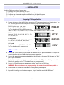
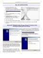
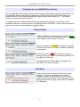
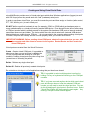
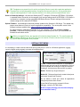
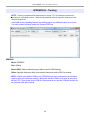
microHAM © 2010 All rights reserved CW KEYER microHAM fax: +421 2 4594 5100 e-mail: [email protected] homepage: www.microham.com Version 7.6 5 December, 2010 1 microHAM © 2010 All rights reserved TABLE OF CONTENTS CHAPTER PAGE 1. FEATURES AND FUNCTIONS .......................................................................................... 3 2. IMPORTANT WARNINGS ................................................................................................. 3 3. PANEL DESCRIPTION ...................................................................................................... 4 Front Panel ................................................................................................................... 4 Rear Panel ....................................................................................................................4 4. INSTALLATION ................................................................................................................. 6 Preparing for Use.......................................................................................................... 6 Macintosh (OS-X) Installation ....................................................................................... 7 Windows (Windows 2000, XP, Vista and Windows 7) Installation................................. 7 Installing microHAM USB Device Router .................................................................8 Configuring microHAM USB Device Router ........................................................... 8 Creating/Using Virtual Ports..................................................................................... 9 5. microHAM DEVICE ROUTER ......................................................................................... 10 Menu: Router ................................................................................................................... 10 Menu: Preset .................................................................................................................... 11 Menu: Device ................................................................................................................... 12 Menu: Virtual Port ............................................................................................................. 13 Menu: Help ....................................................................................................................... 14 Device Configuration Tabs ............................................................................................... 14 Ports Tab ................................................................................................................... 14 Ports: CAT & 2nd CAT .......................................................................................... 16 Ports: CW ............................................................................................................. 19 Ports: PTT ............................................................................................................ 19 Ports: WinKey ....................................................................................................... 20 Ports: Control ........................................................................................................ 20 CW & WinKey Tab ..................................................................................................... 21 CW/WinKey: WinKey Settings ................................................................................... 21 CW/WinKey: CW Keyboard ...................................................................................22 CW/WinKey: Auto Numbering .............................................................................. 22 CW Messages .............................................................................................................23 6. EXTERNAL KEYBOARD ................................................................................................. 24 7. PACKAGE CONTENTS ................................................................................................... 25 8. WARRANTY ..................................................................................................................... 25 SYSTEM CONSIDERATIONS ............................................................................................... 26 HARDWARE SPECIFICATIONS ........................................................................................... 26 DECLARATION OF CONFORMITY ..................................................................................... 27 APPENDIX A – RFI CONSIDERATIONS ......................................................................... 28 APPENDIX B – TRACKING ............................................................................................. 29 2 microHAM © 2010 All rights reserved 1 - FEATURES AND FUNCTIONS No Serial or Parallel port necessary, just one USB port Complete "Computer <-> Radio" isolation • optical isolation of ALL digital signals -> Radio Control, CW, & PTT Compatible with all MS Windows based logging or control software • the special microHAM "USB Device Router" program creates virtual COM ports for full operation with standard Windows applications. customizable presets allow instantly changing CW Keyer parameters to match the program currently in use Integrated computer control port for all radios CI-V, FIF-232, IF-232, RS-232 • fully supports Icom, Kenwood, TenTec, Yaesu and other radios • no separate level converter required Integrated K1EL WinKey™ chip with extended capabilities for superior CW - front panel speed knob - nine (9) user programmable memories - PS/2 keyboard support for CW transmission - PS/2 keyboard/keypad support for message playback and control - PS/2 keyboard or keypad CW works without computer connection - precisely timed auto PTT - selectable side tone - all parameters are stored in nonvolatile memory and reloaded on power up Strong RFI immunity • integrated chokes and filters for best RFI immunity • advanced shielding and circuit design for RFI product suppression Connections: • Computer: USB • Radio: CAT – 1/8,” Paddle – 1/4”, CW Out – RCA, PTT – RCA • Power: 2.1 mm coaxial • Remote: PS/2 - MiniDIN6 Front panel LEDs for indication of CW, PTT, & POWER status Metal/Aluminum case, powder coated and silk screened Free, no time limit, on-line firmware/software upgrades • 2 - IMPORTANT WARNINGS You must set the CAT level jumpers inside the CW Keyer before using it for the first time. ALWAYS check the polarity of the external 13.8 V supply. If your radio includes upgradeable firmware, DO NOT perform any upgrade through CW Keyer. 3 microHAM © 2010 All rights reserved 3 - PANEL DESCRIPTION Front Panel (1) – POWER LED YELLOW color indicates when CW Keyer is turned on (2) – SPEED CW Keyer Speed. Range (MIN, MAX) is defined by software (3) – CW LED RED color indicates when CW keying line is active (4) – PTT LED RED color indicates when PTT is active Rear Panel All connections for the computer, radio and accessories are located on the rear panel. (1) – POWER Standard 2.1mm DC power jack. TIP (center) is positive (2) – CAT 3.5mm (1/8”) jack for radio control TIP - TX data RING – RX data SLEVE - GND (3) - PTT RCA jack for PTT keying output TIP - Signal SHELL - GND Output is an open collector transistor capable of switching up to 28V/0.5A. NOTE: Starting with serial number 260, CW Keyer includes a jumper that allows the PTT output to be used for transceiver PTT or PA PTT. The default setting is transceiver PTT. For PA PTT open the cover and move J9 to the left.. TIP: If CW KEYER is used in a multi-mode environment (CW, Voice and Digital), connect the PA PTT signal in parallel with the transceiver amplifier keying line. IMPORTANT WARNING: DO NOT connect PTT to an amplifier with high voltage or negative voltage keying. 4 microHAM © 2010 All rights reserved (4) – REMOTE MiniDIN6 for a PS/2 keyboard or keypad. (5) – USB: USB B connector for computer connection. Connect a standard USB A-B cable. (6) – POWER SWITCH (7) – PADDLE 6.3mm (1/4") stereo female for paddle input. TIP - DIT RING - DAH SHELL - GND NOTE: The paddle sense can be reversed using Router settings (8) – CW RCA jack for CW keying output TIP - Signal SHELL - GND 5 microHAM © 2010 All rights reserved 4 - INSTALLATION Installing CW Keyer consists of several steps: 1) preparing CW Keyer to work with your radio 2) Install the necessary driver software for your operating system. 3) Configure the driver and/or application software for your specific system 4) configuring Router Preparing CW Keyer for Use 1. Remove the top cover from the CW Keyer and set the CAT jumpers as shown in the following chart. The CAT interface jumpers must be configured to select the proper level for each radio type. RS-232 levels: Elecraft: K2, K3, Icom: 7700, 7800 Kenwood TS-480, 570, 870, 2000, TenTec: all radios with DB9 or DB25 connectors Yaesu: FT-450, FT-847, F-920, FT-950, FT-1000MP, Mark V, Mark V Field, FT-2000, FT-9000 RS232 IF-232 levels: Kenwood: TS-140, 440, 450, 680, 690, 711, 790, 811, 850, 940, 950 IF232 FIF-232 levels: Yaesu FT-100, 736, 747, 757GXII, 767, 817, 840, 857, 890, 897, 900, 980, 990, 1000, 1000D FIF232 CI-V levels: Icom: all radios except 7700/7800 with RS-232 TenTec: all radios with 3.2 mm connector CI-V NOTE: the CAT interface is not configured at the factory. 2. Connect the 3.5 mm stereo plug the on the CAT cable to the CAT jack on the rear of CW Keyer and connect the other end to the appropriate jack on your transceiver. 3. Connect the appropriate user supplied cable from the CW jack on the rear of CW Keyer to the "Key" jack on your transceiver. 4. (Optional) Connect the appropriate user supplied cable from the PTT jack on CW Keyer to the Key input of your amplifier or the PTT/Footswitch input on your transceiver. 5. Connect +13.5 volts from a user power supply to the "power" jack on CW Keyer. WARNING: Be sure to observe the proper polarity – the center pin of the 2.1 mm jack is +. 6. Locate but do not connect the USB cable to CW Keyer and your computer. 7. If you will be installing on a Windows computer, skip to “Installing microHAM USB Router” 6 microHAM © 2010 All rights reserved Mac OS X INSTALLATION 1. Insert the microHAM CD in your CDROM/DVD drive and navigate to Drivers/OS-X or use your web browser to go to http://www.ftdichip.com/Drivers/VCP.htm and down load the latest driver image for OS-X. 2. Open FTDIUSBSerialDriver_v2_2_14.dmg by clicking on it. 3. For OS-X 10.4, 10.5 or 10.6 open FTDIUSBSerialDriver_10_4_10_5_10_6 and follow the instructions to install. 4. Plug in the USB cable 5. Turn on the radio or external power supply. 6. Follow your software developer's instructions to configure their application to work with USB Interface III. MICROSOFT WINDOWS (2000, XP, Vista, Windows 7) INSTALLATION Installing microHAM USB Device Router To install Router click on the Install USB Device Router link on the installation CD or download the most recent installation package from the web site: www.microHAM.com/downloads.html. If you download an updated package, click on "urouter_release_xx_xx.exe" (xx_xx is version) to start the installation. The Windows setup utility will start and ask into which folder Router and its supporting files should be installed. Note: unless you have a very strong reason to install Router elsewhere, please accept the default location. When the Router installation is completed, click "Finish" to launch Router for the first time. Then plug in the USB cable and proceed to configuring Router for your station and software. 7 microHAM © 2010 All rights reserved Configuring the microHAM USB Device Router The microHAM USB Device Router (Router) program provides a Windows compatible configuration tool for microHAM USB Devices (CW KEYER as well as microKEYER, DIGI KEYER and USB Interfaces) and software interface to other Windows applications (loggers, digital mode software, etc.). The software interface is provided as Virtual Serial Ports. To configure and use CW KEYER with Windows based application programs it is necessary to have installed the USB driver, started the Router, and applied power to CW KEYER. Router is then configured to match the requirements of the application (logging) software. CW Keyer Status When the USB driver is installed correctly and CW Keyer is turned on, Router will show a device tab with a GREEN check beside the device name (CW Keyer). When Router shows a YELLOW “X” instead of a green , it means the USB driver is correctly installed but CWKeyer is not turned on. When Router shows a RED “X” instead of a green , it means the device is disconnected and Router does not see the USB part of CW Keyer. This happens when the USB cable is unplugged or the USB driver is not correctly installed. Initial Setup Router must be used to configure CW Keyer for proper operation. The device configuration tab (in the red rectangle) is used to setup each part of the CW Keyer – virtual ports for communicating with the application (Ports), WinKey keyboard CW (keying), and stored CW messages (CW Messages). 8 microHAM © 2010 All rights reserved Creating and Using Virtual Serial Ports microHAM Router provides a set of virtual serial ports which allow Windows applications (loggers) to work with CW Keyer just as they would work with "real" (hardware) serial ports. In order to use these virtual Ports, you must first create the ports and then assign a function (radio control, PTT, CW, WinKey, etc.) to each virtual port. DO NOT define a port that is already in use (for example, COM1 or COM2 which are hardware ports on many motherboards) or a virtual port used by another USB device. Even though Router will not allow using a COM port number which is already present in the system (like hardware COM ports or internal modems), sometimes these ports are hidden. If a device which also uses virtual serial ports (external USB devices, bluetooth devices, mobile phones, PDA etc ...) is not connected to the computer when creating virtual ports in Router, the ports can overlap and will not work properly when you connect such device. IMPORTANT WARNING: Before creating virtual COM ports, attach all external devices you use with the computer and allow them to connect to the system. Restart Router and then create the virtual COM ports. Virtual ports are created from the Virtual Port menu. Create - Creates virtual COM ports. It is possible to select more than one port at a time by holding the Ctrl key on keyboard and clicking on COM port numbers. Creating virtual ports may take a long time (several tens of seconds), be patient. Delete - Deletes any single virtual port. Delete All - Deletes all previously created virtual ports. Do not delete a virtual port until all applications using that port have been closed. TIP: It is possible to select multiple ports at one time by holding Ctrl key on keyboard and clicking on the COM port numbers. TIP: If you have removed another device which used virtual ports and Router does not offer the released COM port number you will need to reset the virtual port bus. You can do this by deleting all virtual ports in Router at once. Select "Virtual Port | Delete All" then create the ports again. Any missing COM port number should appear. 9 microHAM © 2010 All rights reserved 5 - microHAM USB DEVICE ROUTER ROUTER MENU Default Router Settings: used to completely reset Router to factory (default) settings. "Default" removes all device tabs and deletes all stored configuration data, including all user presets, from the Windows Registry. TIP: CW KEYER can be reset to the factory configuration by selecting Default Router Settings followed by Device | Store as Power-up Settings to save the defaults to the keyer's memory. Restore Router Settings: used to restore settings from a urs file created by the backup command. A urs file can be used only with the device for which it was generated (the file contains the unit serial number) on a computer with same port assignments. WARNING: Restoring a backup replaces all current Router settings including presets, use it carefully! Backup Router Settings: used to create backup urs file. This file contains Router settings (including Presets) for all devices defined in Router. Options | General - Load Router on Start-up: when checked, Router will start automatically each time the computer is started or rebooted. - Start Router Minimized: when checked, Router will started minimized Options | Band Map: - Does not apply to CW Keyer Customizable band edge boundaries used to drive the band data output. BCD codes can be customized for driving antenna switches or bandpass filter control. This setting is not used with CW Keyer. Options | Digital Band Map: - Does not apply to CW Keyer Customizable band boundaries for the digital mode operation. These settings are used for the (optional) automatic selection of audio switching and PTT mode based on operating frequency. Careful selection of the "Digital band" is necessary for transceivers which do not have a special mode for AFSK operation or do not report the mode in the computer command set. This primarily effects Kenwood and TenTec transceivers although it applies to some older Icom and Yaesu radios. Options | Audio Devices: - Does not apply to CW Keyer - Don't use audio devices: when checked, Router does not use audio devices and the settings on the Audio Mixer and DVK tabs have no effect. - Manually assign audio devices: when checked, Router will allow the user to select audio devices (sound card) in the appropriate fields at Audio Mixer tab and will actively control the audio devices - Automatically assign microHAM audio devices: when checked, Router will automatically assign proper audio device of the same name if multiple microHAM interfaces of the same kind are connected to the one computer. Options | DVK: - Does not apply to CW Keyer - Voice message time limit: maximum time for each voice message up to 120 seconds. - Sample rate: sampling frequency used during recording and playback of voice messages. - Sample size: sampling size used during recording of voice messages. Sampling size primarily effects audio quality of the messages. 16bit samples provide higher quality than 8bit. Options | USB: - Noise immunity: selects how many times an undelivered USB packet will be repeated before the USB device is disconnected from the operating system. - Response time: selects how long the USB chip in a device will wait for additional data before sending data to the operating system. 10 microHAM © 2010 All rights reserved Minimize: Clicking this will minimize Router to the system tray at the bottom right corner of the Windows Taskbar (the "System Notification Area"). . TIP: When Router is minimized you can restore it by double-clicking on the Router tray icon. You can also restore Router by double-clicking on the Router icon on the desktop or restarting Router from the Programs menu. Exit: Clicking on this item will terminate Router. NOTE: when Router is terminated, application software will be unable to communicate with CW Keyer and the radio. PRESET MENU The requirements of each program are different and each one may handle radio control, CW and PTT in its own way. In some cases what works for one application may not work properly with another. To get maximum performance from CW Keyer, you may wish to customize the settings for each application. For easy switching among applications, Router supports up to 12 user definable Presets. Different configurations can be stored in these presets and recalled almost instantly simply by clicking on the preset button. Each preset contains the settings for all devices connected to, and controlled by, Router. For example, if Router controls a microKEYER, a CW Keyer and a USB Interface, each preset remembers the settings for all devices including the assignment of COM ports and the contents of all sub-tabs except the FSK/CW Messages and DVK tabs. NOTE: Presets for various loggers are not available until they have been saved by the user using Preset | Save as. For setup instructions for various loggers refer to Setup Guide documents available in Router Help menu (Use Help | Download Documents first if Help | Setup Guides are not available or incomplete). There are three ways to apply a preset once it is created: 1. Click on Preset and select the desired preset from the pull-down menu. 2. Click on a preset button. To have buttons visible in Router, Preset | Show Buttons must be checked. When the settings from a preset are applied, a green light located in the preset button is lit. This green light is on ONLY when all settings in Router are same as those stored in the preset. 11 microHAM © 2010 All rights reserved 3. By right clicking on the system tray icon when the Router is minimized. The presets and the current router configuration are stored to the registry when Router is closed and recalled when Router is loaded. Save as - Saves the current Router settings to a preset for future use. Rename - Allows renaming of an existing preset. Delete - Delete chosen preset. Show buttons - When checked, Router shows the preset buttons. DEVICE MENU Router can control several devices. This allows configuring the settings for all connected devices at one time by using the Presets. Each device has its own tab (page) in the main Router notebook. The content of a device tab depends on device type. Adding a device is automatic when Router detects a new device. Once detected, a device remains in Router even though device is disconnected. Each device is identified by a unique serial string. Rename – Creates a custom device name. This is useful if two or more devices are connected to the Router. For example CW KEYER, micro Keyer and USB Interface II can be renamed to more identifiable names as shown here. Delete - Removes a device from the Router. Only disconnected devices with a RED “X” on device tab can be removed. To disconnect a device from Router, unplug the USB cable from the computer or device. Save Template - will save the current Router settings to template file. When clicked, Router will open a standard File Save dialog window – the default location is C:\Documents and Settings\All Users\Application Data\microHAM\cfg. If a hypertext (html) or plain text (txt) documentation file of the same name as the template is present in the same directory, it will be associated with the template. Load Template – will automatically configure Router from a template (*.tpl file). When clicked, Router will open a standard File dialog – the default location is: C:\Documents and Settings\All Users\Application Data\microHAM\cfg - and the desired template can be chosen. When Router loads a template, it looks for an html or txt file with the same name as the template in the same directory. If such file is found, it is displayed. 12 microHAM © 2010 All rights reserved TIP: Templates are a powerful tool for quickly configuring Router to work with a particular application. Template files are interchangeable between computers and are well suited for cloning setups when using the same application in multi-computer stations or for sharing custom setups between users. Store as Power-Up Settings: - will store the WinKey and PTT settings to CW Keyer's EEPROM. If CW Keyer is operated without connection to the computer it will use the settings stored in EEPROM. If CW Keyer is connected to a computer running microHAM USB Device Router, Router's settings will be used but default settings will be retained in EEPROM. Upload Firmware: microHAM will occasionally release updates to the firmware in CW Keyer. The update may support news feature in Router or improve application compatibility. The recent public version of the firmware is always available from www.microHAM.com/downloads.html. To update firmware, download the firmware file to your computer, then click on Device | Upload Firmware. A Windows file dialog will open; navigate to the directory into which you downloaded the firmware file and select the file. TIP: When you upgrade Router, the upgrade will include the latest firmware file. The new firmware will be automatically uploaded to CW Keyer when the new version of Router connects for the first time, you have just to allow the upgrade when prompted. VIRTUAL PORT MENU It is necessary to create several virtual serial ports (COM ports) in order for a Windows application (logging, control or digital mode program) to access microHAM devices. Create - Creates virtual COM ports. It is possible to select several ports at one time by holding the Ctrl key on the keyboard and clicking on COM port numbers. Creating a virtual port may take a while, be patient. Delete - Deletes any single virtual port. Delete All - Deletes all previously created virtual ports and resets Virtual Serial Port bus. Do not delete a virtual port unless all applications using that port have been closed. Virtual Serial Ports can be reviewed in Device Manager, under the ELTIMA folder. NOTE: Properly working ports should not display an exclamation mark (!). 13 microHAM © 2010 All rights reserved HELP MENU Manuals: Link to microHAM manuals located on your system. Setup Guides: Link to software configuration guides for many common applications. Cable Schematics: Link to cable diagrams. Download Documents: Downloads microHAM documentation including updated manuals and setup guides. You may specify the products for which you want documentation. NOTE: Requires an Internet connection. microHAM Home Page: Link to www.microHAM.com microHAM Downloads Page: Link to www.microham.com/contents/en-us/d29.html Show Tooltips: When checked, small, single line help is displayed below the mouse cursor. Update Router: Download and install the most recent version of Router. About: Shows the Router's internal version number Change logs: Shows the Router and firmware changes. DEVICE CONFIGURATION TABS There are three (3) tabs for configuring CW Keyer. Any change to the first two (2) tabs are applied immediately to CW KEYER. Changes in Messages are NOT applied automatically. To store them use buttons Store or Store All. Ports - used to assign virtual ports to the CW Keyer for use by applications. CW/WinKey - used to configure the operating parameters of the internal WinKey keyer IC. CW Messages – used to configure stored CW messages. 14 microHAM © 2010 All rights reserved PORTS TAB Once the virtual ports have been created they must be associated with a specific device channel (e.g., Control, CW, PTT, etc.). These assignments should correspond to settings of the application software and must be configured first in Router and then in the application (e.g., logging program). Proper configuration of the port assignments in this tab is most important for integration with loggers. Read the following information carefully. CW KEYER has five functions with indication of the state and settings applied by the host application ● ● ● ● ● ● CAT (uses RxD and TxD) 2nd CAT (virtual “fork” for the main CAT channel) CW (uses DTR or RTS) PTT (uses DTR or RTS) WinKey (uses TxD, and RxD – cannot shared a port with any other function) Control (uses TxD and RxD) General note: Most applications will support only one method of CW output at a time. If the application uses WinKey, the CW port should be "none" and vice versa. 15 microHAM © 2010 All rights reserved CAT PORT & 2nd CAT PORT The CAT channel is used by the application software to control transceiver frequency, mode, T/R switching and many other parameters. The application communicates with the radio using a serial protocol. Although most modern radios implement some form of serial control, nearly every radio implementation is different. The degree of control available for each radio depends on that radio and the application (logger or digital program). NOTE: The port number assigned in Router MUST match the port number assigned in the host application. First configure the virtual COM ports in Router then configure the application. When a COM port is assigned in the Router but not in the application (or the application is not running) Router will indicate the channel is closed. When an application opens the COM port assigned for control (usually at start-up), Router shows the channel as open and displays baud rate, data bits, parity and number of stop bits used by the application. For example, 4800 8N2 means: 4800 baud, 8 bits data length, parity = none, and two stop bits. Data flowing through the CAT channel is indicated by two arrows. A green arrow indicates data flow from the host application to the radio and a red arrow indicates data flow from the radio to the application. TIP: If the application provides for PTT (T/R) keying by radio control (CAT) turn this function OFF. PTT by CAT is not reliable because RFI can prevent the radio from switching back to receive. There is a dedicated T/R switching channel for this purpose called PTT. NOTE: If your radio does not support handshake (most do not). Configure DTR and RTS settings in your application program (logger) for Always On or Always Off. Do not select “Handshake.” For Router to determine the operating frequency and mode, it must know what radio (CAT protocol) being used. To select the radio, click the Set button, choose your radio in the Radio combo box, select communication speed in the Baud rate box, and set the CI-V address for Icom and some TenTec radios. TIP: Disable the Autobaud function in any Icom transceiver used with Router. Configure the radio, Router, and your application software to operate at 9600 or 19200 baud. Disable router queries – When this box checked, Router will not poll the radio for frequency and mode when that information is not available from the communication between the application and radio. NOTE: "Disable router queries" disables Router polling only when the port has been opened by an application program. When the virtual port is closed, Router always polls the radio to support the automatic switching functions of CW KEYER. If it is necessary to disable all polling, select one of the "none" options in the Radio box. 16 microHAM © 2010 All rights reserved WARNING: DO NOT select "Disable Router queries" unless you have a specific reason to do so. Router only polls for information that is not requested by the logger and does not interfere with logger polling. Disabling Router queries may result in incorrect frequency and/or mode decoding and can have a serious impact on overall operation. PW1 on radio bus – When this box checked, Router periodically generates an Icom "Transceive" broadcast to keep the PW1 synchronized. NOTE: Check this box if you have an IC-PW1 or other Icom compatible accessory physically connected (in parallel with the transceiver). Do not check this box if the only connection is to the transceiver and the PW1 or other other accessory is connected to the accessory CI-V PA port (described later). Port: Defines a virtual or hardware serial port for an SDR radio used with the MKII. The CAT connection in CW KEYER is disabled. This function is not currently supported. SDR Tracking: Tracking: This function allows an external receiver to track the transceiver attached to the CW KEYER. NOTE: The transceiver attached to CW KEYER must be properly interfaced and CAT must be functioning properly. Tracking does not work for “no radio” choices. Radio: Specifies SDR receiver model. Source QRG: Specifies whether the SDR will track the transceiver transmit or receive frequency. . Port: Specifies COM port used to communicate with the SDR. Offset: Frequency offset between the receiver and transceiver. Default is 0Hz, resolution is 1Hz. NOTE: For specific receiver configurations, please refer to Appendix C.. The bottom two-thirds of the Radio window is a serial communication monitor. The monitor uses colors and tags to indicate which device is responsible for the data. Black queries (H1-TX or H2-TX) and grey radio responses (H1-RX or H2-TX) are from the "host" application (e.g., logger), H1 indicates the host application on the main CAT port, H2 is the host application on the 2nd CAT port. Green packets (R-TX and R-RX) are polls/responses from/to Router and not routed to the application. Router monitors the communication when the host application performs control and polls the radio periodically for any missing information (VFO frequencies and mode). Because some applications do not poll the radio regularly or completely, Router must break this communication to update its internal state. In order to avoid confusing the application when Router polls the radio, data from the application is buffered and sent to the radio after Router receives a response to its query. If Router does not receive response to a poll within the time allowed or does not understand the response, it displays "oldest query discarded" but forwards all data to the virtual serial port to avoid confusing the application (logger). Since USB transmits data in frames with a delay between frames, Router indicates frame boundaries with three dots (...). When a packet ends with three dots it means that the data continues in the next frame. 17 microHAM © 2010 All rights reserved 2nd CAT PORT Beginning with version 7.0, Router provides unique control capability: the 2nd CAT Port is an intelligent data fork (software 'Y' connector) that allows a second application to share control of the radio. Router monitors when data is sent from each application and routes the radio's responses to the correct virtual port. IMPORTANT: Both applications must use same communication parameters (baud rate, data length, parity and number of stopbits) for proper operation! Neither CAT port has priority. Polls/commands from the application are processed alternately. In order to avoid collisions and confusion due to unexpected data, responses from the radio are returned only to the application that generated the command. Unsolicited data such as automatic frequency/mode updates (Icom "transceive" packets or "Auto-information" data from Kenwood, Elecraft and recent Yaesu transceivers) is forwarded to both CAT ports. Due to physical limitation of data channel throughput and the controller capabilities in various transceivers, there are several important rules which must be observed. ● Combined data from both applications must not exceed maximum throughput of the radio control port and transceiver controller. In other words, the polling rate from one application may need to be decreased to provide data space for the second application and vice versa. ● Applications must be tolerant of delayed responses from the radio. Each application must wait for the radio to respond when the another application is communicating with the radio. ● Due to protocol deficiencies in handling VFO split commands with many transceivers (particularly Icom), split mode must be initiated and ended by only one application and manual split control (from the front panel of the radio) should not be used. NOTE: Despite extensive testing using various combinations of applications for the CAT and 2nd CAT ports, microHAM cannot guarantee proper operation with every potential combination of applications. 18 microHAM © 2010 All rights reserved CW PORT By its very nature, USB is not well suited to transfer the real time events required for CW keying. In addition to the latency inherent in the USB protocol, delays due to CPU load, internal Windows message processing (interprocess communication) and data flow from another peripherals sharing same the USB root hub can result in transmitted characters that are garbled. To minimize these unwanted operating system effects Router uses a specially developed oversampling and prediction algorithm to assure the smoothest possible transfer of control signal events over USB. Using these techniques, CW keying in the Router is, in most cases, usable up to 50 WPM if the application generates keying signals accurately and does not consume 100% of CPU time at the highest priority class. Router allows assigning a virtual port for software CW using DTR or RTS signals. DTR* and RTS* are identical to DTR/RTS except that the output is inhibited for one second after the COM port is opened. RTS*/DTR* should only be used with programs that cause unwanted key-ups during startup. TIP: More applications use DTR for CW than RTS. When an application opens the COM port (usually at start-up), Router will indicate the channel is open. The state of the CW channel is indicated by a red arrow. If port is opened, it does not mean that it is properly configured. The red arrow will light in time with the transmitted CW when the port is properly configured. To test CW operation, click on the Test button with no port assigned or the port closed. PTT PORT The PTT channel is used for T/R switching of the transceiver. Router allows assigning a virtual serial port to the PTT channel and supports PTT via DTR or RTS. DTR* and RTS* are identical to DTR/RTS except that the output is inhibited for one second after the COM port is opened. RTS*/DTR* should only be used with programs that cause unwanted key-ups during startup. TIP: More applications use RTS for PTT than DTR. When a COM port is assigned in the Router but not in the application (or the application is not running), Router shows the channel as closed. When an application opens the COM port (usually at start-up), Router shows the channel as open. Activity and the state of PTT channel is indicated by arrow. If port is opened, it does not mean that is properly configured for PTT keying. The arrow will light during the entire transmission when port is properly configured. Operation of the PTT outputs is described in chapter 15.3 TIP: Always use serial PTT instead of PTT by CAT. CAT PTT can be unreliable due to RFI and timing issues. To test operation of the PTT, click on the Test button with no port assigned or the port closed. 19 microHAM © 2010 All rights reserved WINKEY PORT WinKey is a unique external CW processor developed by Steve Elliot, K1EL. This CW processor supports paddle input like any other electronic keyer, offers many configuration options, and in addition converts ASCII data from the computer to Morse characters. This unique property assures perfectly timed CW output from the computer regardless of OS load. More detailed instruction for configuring WinKey is found in the description of the CW tab. When a COM port is assigned in Router but not in the application program (or the application is not running), Router shows the channel as closed. TIP: If you see settings other than 1200 8N1 or 1200 8N2, the application is not configured correctly for WinKey. Data flow is indicated by two arrows. The green arrow indicates data flow from the application to WinKey and the red arrow indicates data flow from WinKey to the host application. To test WinKey, click the Test button with the channel unassigned or closed. Mon: “WinKey Monitor” allows capturing communications between the application and WinKey. The WinKey monitor operates the same way as the CAT port monitor. WinKey Monitor should not be used under normal conditions. However, if there are problems with WinKey and the controlling application, it may be useful to Start a capture and minimize the window. When a problem is noticed, the window can be opened and the log Saved for analysis. WinKey Monitor is circular – only the last 20 kilobytes or so will be saved in order to prevent creating very large files. WK Monitor will display a description of each command from Router or the application and “decoded” response from WinKey. If a line ends in three dots (...) it means that the command or response has been broken across two USB packets. CONTROL PORT The Control Port allows an application program (logger) that implements the microHAM Control (SO2R) Protocol to use the stored CW messages. This port should normally be set to "none." The Mon button opens a logging window that permits capture of Protocol data between the application and Router for later analysis. The buffer captures the last approximately 20K of data. Do not enable logging unless necessary for debugging purposes as it imposes a minor performance penalty. 20 microHAM © 2010 All rights reserved CW/WINKEY TAB This tab provides the configuration for the internal, WinKey based, CW keyer. A complete WinKey manual can be downloaded from: HTTP://k1el.tripod.com/docfiles.html. Thanks to Steve Elliott, K1EL for this great product. WinKey can be controlled by a logging program or operate in stand alone mode. Router controls the speed range, paddle mode and other timing characteristics of Winkey. When an application opens WinKey, all buffer handling and speed changes are strictly under application control. When the port is closed, the WinKey operating parameters can be changed from this tab. Every change is applied immediately. The WinKey CW output (pin 3) is wired in parallel with the serial CW output. The WinKey PTT output (pin 5) is connected by a jumper (SO1R/SO2R) to the PTT jack or pin 6 of the REMOTE jack. Paddle Mode ● Iambic A (Curtis) ● Iambic B (Accu-keyer) ● Ultimatic (Single lever) ● Bug Keyer (Vibroplex emulation) Priority – In Ultimatic mode one can chose DIT or DAH priority for dual lever paddles. If no priority is selected, the keyer works in a "last paddle wins" mode. Paddle set point - controls when WinKey begins looking for a new paddle press after sensing the current one. The default value is one dit time (50) and is adjustable in percent of a dit time. Disable paddle memory – When checked, DIT (or DAH) insertion is disabled. Swap paddles - Reverse paddle sense for left handed operation or improperly wired paddle. Auto space - Keyer generates automatic character space. CT space - Selects “contest” word space (six dits long instead of seven). Speed pot min/max - Min/Max value of the front panel speed knob (9) in range 5 to 99 WPM. Farnsworth speed – Sets the Farnsworth keying speed (10 to 99 WPM range, 0 disables this feature). DIT / DAH - DIT/DAH ratio from 1:2 to 1:4 in hundreds. Accepted number are from 200 to 400. Weighting - Weighting in percentage (from 10 to 90%). 1st extension - Extension of the first dit or dah in milliseconds (usable for QSK only). Keying compensation - Extension of each dit and dah in milliseconds (usable for QSK only). 21 microHAM © 2010 All rights reserved PTT – Selects PTT (semi break-in) or QSK operation of the PTT output. In PTT output will be controlled by the WinKey or Serial PTT. In QSK, the transceiver PTT will not be activated and the PA PTT output will follow the CW output. PTT Lead can be specified for WinKey PTT in 10 millisecond increments. Minimum lead is 0 ms, maximum delay is 2500 ms. PTT tail specifies the length of time the PTT will remain closed following the last CW character. WinKey has a minimum tail of one word space (6 elements). PTT tail applies an additional delay that can be set for a “constant” 10 to 2500 millisecond delay in 10 ms steps or an additional one word space (12 elements total), 1.33 word space (14 elements), 1.66 word space (16 elements) or two word spaces (18 elements). Note: most logging software has its own PTT lead/tail settings for serial (program generated) PTT. Side Tone - 1350, 675, 450, 388 Hz or OFF. The volume is not adjustable. Note: Side tone is generated by the CW Keyer MPU, not by pin.5 of WinKey. Pin 5 is reserved for the PTT or for CW output to a second radio. Speed Step - defines the steps (in WPM) by which the +/- keys on the optional keypad will change the speed. The enter key restores the speed set by the Speed pot. CW Keyboard Type ahead – enables type ahead when using a PS/2 keyboard. Characters are transmitted after a space (word mode) or after the buffer has reached its limit (16 characters). QWERTZ layout – changes keyboard layout to European QWERTZ standard. Auto Numbering Leading zero as T – sends leading zeros in contest report as T. For example 001 will be sent as TT1. Zero as T – sends all "zeros" in contest report as T. For example number 100 will be sent as 1TT. One as A – sends all "ones" in contest report as A. For example number 101 will be sent as A0A. Nine as N – sends all "nines" in contest report as N. For example number 199 will be send as 1NN. Report 5NN – send 5NN before contest serial number. Other message functions can be controlled by an external PS2 keyboard or keypad. See: Chapter 6 - External Keyboard. 22 microHAM © 2010 All rights reserved CW MESSAGES TAB CW Keyer supports nine messages of up to 50 characters each which can be stored are stored in nonvolatile memory. Each memory may have a programmable repeat delay and/or call another memory. Commands which may be included in a memory are: Merge: merge two characters without a letter space – [M]AS will sound AS .-... Cancel WPM: restore speed set by the Speed pot. Set WPM: force WPM to selected speed regardless of position of speed knob. Set Key: close CW output for selected time in seconds. Set Wait: pause "n" seconds during playback. Jump to: jump to the selected message Delay: delay in seconds before executing the jump Test: will play a message without storing it Store: saves one message to non-volatile memory Store All: saves all messages to non-volatile memory Load from File: loads all messages from file Save to File: saves all messages to file Messages can also be saved and replayed using an external PS/2 keyboard or paddles and PS/2 keypad. NOTE: Messages are not saved or loaded with Presets. 23 microHAM © 2010 All rights reserved 6 - EXTERNAL KEYBOARD CW Keyer allows transmitting CW from a PS2 keyboard attached to the Remote jack. A numeric PS/2 keypad may also be used to record and play back CW messages (memory keyer). NOTE: The keyboard or keypad must be PS/2. A USB device and PS/2 adapter. will not work properly. CW Keyer allows keyboard transmission, saving messages to memory, playing stored messages, setting speed, and tune mode. During record mode it is possible to record characters typed on the keyboard or entered on the paddle. Number Pad Key Standard Key Function NUM LOCK Start/Stop recording of message (record mode is indicated by NUM LED, if present) NUM * Tune (Cancel by NUM 0 or ESC) NUM 0 ESC NUM 1 – NUM 9 F1 – F9 NUM ENTER Playback: Play message Recording: Select message slot to record Switch between Speed mode and Serial Number mode NUM / NUM - Recording: abort recording without saving the message Loop last message – default is one second. Following NUM DEL with a number on the numeric pad will set the delay NUM DEL NUM + Playback: Stop transmitting (clear message/buffer) ALT Hold to set serial number CW Speed mode PG UP Increase CW speed (step defined by configuration) Serial Number mode UP Decrement number by one CW Speed mode PG DN Decrease CW speed (step defined by configuration) Serial Number mode DN Decrement number by one CW Speed Mode HOME Reset Speed to Pot Serial Number mode ENTER Transmit number with optional report and increase number by one (format defined by configuration) F10 Toggle PTT | Transmit Gap (½ dit space) Space Transmit a space. If “type ahead” is selected, the character is pushed into the type ahead buffer and transmitted in sequence 0-9, A-Z !“$&='(),-./:; ? Transmit the character. If “type ahead” is selected, the character is pushed into the type ahead buffer and transmitted in sequence 24 microHAM © 2010 All rights reserved 7 - PACKAGE CONTENTS The product includes CW KEYER, USB cable, coaxial 2.1mm/5.5mm power plug, and CD-ROM containing the microHAM USB Device Router program and documentation. If the shipment is incomplete, please contact us at the following address: E-mail: [email protected] fax : +421 2 4594 5100 by Post: microHAM s.r.o. Nadrazna 36 90028 Ivanka pri Dunaji SLOVAKIA 8 - WARRANTY microHAM warrants this product for three (3) years. The product must not be modified in any way or the warranty is voided. Cables are warranted against defects in materials and workmanship for a period of 60 days. What is covered: During the warranty, microHAM, s.r.o., will repair or replace defective product at their sole discretion. You must send the unit postpaid with a copy of the original invoice to the distributor from whom you purchased the product. microHAM will pay return shipping. What is not covered: This Limited Warranty does not cover (1) correction of installation or software errors in the user's computer(s), (2) damage caused by misuse, negligence, user modifications or failure to follow the user manual, (3) connection to improper or excessive voltage or voltage surges, (4) the incorrect installation of any cables connected to the device by the user or (5) weather related storm, lightning or electrostatic discharge damage. microHAM USB Device Router (the software) is provided “as is” without guarantee of compatibility with any specific operating system, computer, peripheral or accessory. microHAM assumes no liability or responsibility for damage to other devices or injuries to persons as a consequence of using our products. If the terms of the above warranty are not acceptable, return the unit, all associated documents and accessories in the original unopened package, prepaid, to microHAM or to your supplier for refund less shipping and a restocking fee. 25 microHAM © 2010 All rights reserved System Considerations CW Keyer can be used with a wide variety of application packages. The capabilities of those packages will have significant impact on the level of computing power needed to utilize CW Keyer. When used with Windows based contest logging applications like N1MM Logger, Win-Test, and WriteLog or Windows based general logging applications like DXBase, DXLab Suite, DX4Win, Logger 32 and others, the microHAM control and interface application “microHAM Router” must run with the application. Since both the logging program and microHAM Router are real-time applications, system performance will be dependent on both CPU speed and the amount of available RAM. While microHAM Router will run on slower computers, the minimum tested system is a 1.6 GHz Pentium IV, Windows 2000, 512 MB RAM, CD-ROM, and USB 1.1 port. Whether Router can run as designed on slower machines with less memory and leave enough resources for application programs has not been determined. microHAM Router is not supported on any 16 bit version of Windows (95, 98, ME, SE). In order to provide sufficient performance for simultaneous operation of microHAM Router, a logging application, Internet connectivity and other accessory programs, the recommended system is a 2 GHz PC compatible computer with Windows XP Home or higher, 1 GB RAM, CD-ROM, root USB 2.0 port, a transceiver with supported control protocol and logger, control, or digital mode software. CW Keyer is also compatible with Apple Macintosh running OS 10.5 or later. It is directly supported by MacLoggerDX (www.dogparksoftware.com/MacLoggerDX.html) by Don Agro, VE3VRW and µH Router (http://homepage.mac.com/chen/w7ay/Router/index.html) by Kok Chen, W7AY. Hardware Specifications USB: USB 2.0 Full speed , USB 1.1 compatible Power consumption: USB – less than 100mA; Transceiver – less than 100mA at 13.8V (max. 16V) Radio Port: RxD, TxD – max. 57,600 Baud Levels: Jumpers selectable TTL, inverted TTL, open collector bus, RS232 CW: open collector, max 30V/400mA PTT: open collector, max 30V/400mA Dimensions: W 103mm (4") x H 44mm (1 3/4") x D 85mm (3 3/8") Weight: 600g (1.3 lbs.) 26 microHAM © 2010 All rights reserved DECLARATION OF CONFORMITY Federal Communications Commission Statement (USA) This device complies with Part 15 of the FCC Rules. Operation is subject to the following two conditions: (1) this device may not cause harmful interference, and (2) this device must accept any interference received, including interference that may cause undesired operation. European Union Declaration of Conformity microHAM, s.r.o. declares that the products: Product Name: CW Keyer Conforms to the following Product Specifications: EN 55022: 1998 Class B following the provisions of the Electromagnetic Compatibility Directive 89/336/EEC 27 microHAM © 2010 All rights reserved APPENDIX A – RFI CONSIDERATIONS A few guidelines to eliminate problems caused by RFI: 1. Proper grounding of all electronic equipment is critical. A modern station contains many, diverse, types of interconnected and interrelated equipment: transceiver, power amplifier, computer, control boxes, switch boxes, and power supplies. Each of these must be individually grounded with a separate connection to a single common ground point, thus forming a star ground connection. Proper grounding of computers, both "desktop" and laptop is often overlooked. A separate ground connection should be run from the computer to the station common ground point. The best place to ground a computer is a screw with a good connection to the case. On a laptop, this is often the retaining screw on a D-sub connector (e.g, VGA output); on a "desktop" it is often the screws holding the power supply. It is absolutely important to prevent ground currents from flowing to the common ground point by way of the signal cable. If you use a microHAM "keyer," a good test is to remove the DB15/DB37 connector and USB cable from the keyer and measure the resistance from the shell of the DB15/DB37 to the shell of the USB cable. There should be NO MORE than FIVE (5) Ohms (and preferably less than TWO Ohms) between them. Note: many PC manufacturers fail to provide an adequate connection between the shell of the USB connector and the PC case. If this is the case, a connection can be established by bridging a folded piece of aluminum foil between the shell of the USB connector and the PC case. 2. Power all your equipment from a single wall outlet. The "safety ground" often exhibits excessive noise between power outlets - sometimes often due to other equipment powered from the same branch circuit. It is always better to avoid this source of noise/interference. It is also a good idea to check the power distribution for loose connections, reversed neutral/ground, open ground and other wiring problems. 3. Sometimes, the USB cable can be a source of RF interference - the cable might have inadequate shielding or the transceivers in PC might be improperly designed causing data flowing inside the cable to be reflected as a common mode current on the shield of the cable. This common mode current can radiate a significant "digital noise." If this is the source of your problems, it can be significantly reduced or eliminated using ferrite chokes on both ends of the cable. Two or three turns through a #31 mix FT240 toroid are better than the common snap-on ferrites of unknown mix. 4. Often, another cause of RFI problems is a common mode current flowing along the antenna feedline into the shack. It is a common misconception that the only thing required of a feedline is that it have low SWR. Unfortunately, a low SWR does not guarantee low common mode current. These common mode currents are conducted into the shack where they can radiate from the feedline, induce currents in any nearby metal object, and/or be conducted into the interconnected equipment. Common mode currents on a feedline are indicated by problems that differ in intensity from one band to another or from one end of the band to another, by problems that change when a feedline is moved or its length changed, where the problem moves from one piece of equipment to another based on band, and/or where the severity changes with transmit power level. The solution is to use common mode chokes to prevent the current from entering the shack. This topic has been given thorough treatment in recent works by W1HIS and K9YC. W1HIS: http://www.yccc.org/Articles/W1HIS/CommonModeChokesW1HIS2006Apr06.pdf K9YC: http://www.audiosystemsgroup.com/RFI-Ham.pdf 28 microHAM © 2010 All rights reserved APPENDIX B – Tracking NOTE: Tracking is experimental code started in Router 7.5.0 for linking the transceiver frequency to a tracking receiver. Mode linking and bidirectional frequency tracking are not currently supported. microHAM will be expanding features and adding support for additional radios in the future. The initial version has been tested with Perseus SDR only. PERSEUS Radio: PERSEUS Port: COM10 Source QRG: Defines which frequency will be used for SDR tracking Offset: Specifies frequency offset from tracking frequency send to SDR for tracking. NOTE: COM10 is the default COM port for PERSEUS can only be changed in the Windows registry (refer to the Perseus manual). Make sure that the COM10 is not used by any other device in PC. Then create virtual COM10 in Router and do not use this COM port number for any purpose other than tracking. 29


![ft.757gx ]i hf all mode computer aided transceiver](http://vs1.manualzilla.com/store/data/005735092_1-f8362b9c1e3279439f07a335507c2c8e-150x150.png)