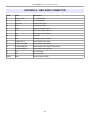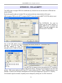
1
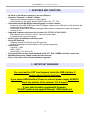
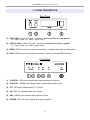
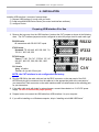
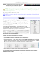
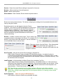
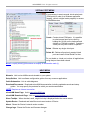
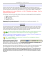
microHAM © 2016 All rights reserved USB Interface II microHAM fax: +421 2 4594 5100 e-mail: [email protected] homepage: www.microham.com Version 8.0 1 March 2016 1 microHAM © 2016 All rights reserved TABLE OF CONTENTS CHAPTER PAGE 1. FEATURES AND FUNCTIONS ...................................................................................................3 2. IMPORTANT WARNINGS .......................................................................................................... 3 3. PANEL DESCRIPTION .............................................................................................................. 4 Rear Panel ............................................................................................................................ 4 Front Panel ............................................................................................................................4 4. INSTALLATION ......................................................................................................................... 5 Preparing for Use................................................................................................................... 5 Macintosh (OS X) Installation................................................................................................. 6 Windows ............................................................................................................................... 6 Installing microHAM USB Device Router .........................................................................6 Configuring microHAM Device Router ......................................................................6 Creating and Using Virtual Ports ...............................................................................6 5. microHAM DEVICE ROUTER ................................................................................................... 9 Menu: Router ........................................................................................................................ 9 Menu: Preset ...................................................................................................................... 10 Menu: Device ...................................................................................................................... 11 Menu: Virtual Port ............................................................................................................... 12 Menu: Help .......................................................................................................................... 12 Ports Tab............................................................................................................................. 13 Radio Port ..................................................................................................................... 13 CW Port......................................................................................................................... 14 PTT Port........................................................................................................................ 14 Squelch Port ................................................................................................................. 14 6. SETTING AUDIO LEVELS ....................................................................................................... 15 7. SYSTEM CONSIDERATIONS ................................................................................................. 16 8. PACKAGE CONTENTS ........................................................................................................... 17 9. WARRANTY ..............................................................................................................................17 10. SPECIFICATIONS .................................................................................................................... 18 Hardware Specifications ..................................................................................................... 18 DECLARATION OF CONFORMITY ......................................................................................... 19 APPENDIX A - DB15 RADIO CONNECTOR ........................................................................... 20 APPENDIX B – FSK WITH MMTTY.......................................................................................... 21 APPENDIX C – RFI Considerations ....................................................................................... 22 APPENDIX D – Cables and Bridges ...................................................................................... 23 2 microHAM © 2016 All rights reserved 1 - FEATURES AND FUNCTIONS No Serial or Parallel port necessary, just one USB port Complete "Computer <-> Radio" isolation • bidirectional transformer isolation of audio signals • optical isolation of ALL digital signals: Radio Control, CW, PTT, FSK Compatible with all MS Windows based logging or control software • the special microHAM "USB Device Router" program creates virtual COM ports for full operation with standard Windows applications. • customizable presets allow instantly changing USB Interface II parameters to match the program currently in use Integrated computer control port for all radios CI-V, FIF-232, IF-232, RS-232 • fully supports Icom, Kenwood, TenTec, Yaesu and other radios • no separate level converter required Squelch input for additional software control Strong RFI immunity • integrated chokes and filters for best RFI immunity • advanced shielding and circuit design for RFI product suppression Connections: • Computer – USB • Radio – DB15 • Sound Card – 2 x 3.5mm (1/8”) Front panel LEDs for easy visual feedback of CW, PTT, SQL, POWER and radio control data Metal/Aluminum case, powder coated and silk screened Free, no time limit, on-line firmware/software upgrades 2 - IMPORTANT WARNINGS You must set the CAT level jumpers inside the USB Interface II before using it for the first time. If you power USB Interface II from an external power supply ALWAYS check the polarity of the external 13.8 V supply. If your radio includes upgradeable firmware, DO NOT perform any upgrade through USB Interface II. 3 microHAM © 2016 All rights reserved 3 - PANEL DESCRIPTION Rear Panel (1) – INPUT (MIC): 3.5mm (1/8") jack – connects to sound card Line In or microphone TIP – Signal, RING – NC, SHELL - Signal Ground (2) – OUTPUT (SKP): 3.5mm (1/8") jack – connects to sound card Line Out or speaker TIP – Signal, RING – NC, SHELL - Signal Ground (3) - RADIO: DB15F connector for radio interconnection – a detailed description is in Appendix A (4) - USB: USB B connector for computer connection. Connect a standard USB A-B cable. Front Panel (1) – CONTROL: RED color indicates when radio sends data to computer (2) – CONTROL: GREEN color indicates when computer sends data to radio (3) – PTT: RED color indicates when PTT is active (4) – CW: RED color indicates when CW is active (5) – SQL: GREEN color indicates when squelch is active (6) – POWER: YELLOW color indicates when unit is powered 4 microHAM © 2016 All rights reserved 4 - INSTALLATION Installing USB Interface II consists of several steps: 1) prepare USB Interface II to work with your radio 2) install microHAM USB Device Router (the control and interface software) 3) configure Router Preparing USB Interface II for Use 1. Remove the top cover from the USB Interface II and set the CAT jumpers as shown in the following chart. The CAT interface jumpers must be configured to select the proper level for each radio type. RS232 RS-232 levels: All transceivers with RS-232 CAT inputs. IF-232 levels: Kenwood: TS-140, 440, 450, 680, 690, 711, 790, 811, 850, 940, 950 FIF-232 levels: Yaesu: FT-100, 736, 747, 757GXII, 767, 817, 840, 857, 890, 897, 900, 980, 990, 1000, 1000D CI-V levels: Icom: all radios TenTec: all rigs with 3.5mm jack IF232 FIF232 CI-V NOTE: the CAT interface is not configured at the factory. 2. Plug the DB15M on the radio cable set into the DB15 connector on the rear panel of the DIGI KEYER and plug ALL connectors from the cable set to the appropriate jacks at the rear panel of your transceiver. Each connector on the radio interface cable is marked same as the matching jack on your transceiver. 3. If the radio cable ends with leads for external power, connect these leads to a 12-16V DC power supply. Be sure to observe the proper polarity. 4. Prepare but do not connect the USB cable from USB Interface II to your computer. 5. If you will be installing on a Windows computer, skip to “Installing microHAM USB Router” 5 microHAM © 2016 All rights reserved Mac OS X INSTALLATION 1. Insert the microHAM CD in your CDROM/DVD drive and navigate to Drivers/OS-X or use your web browser to go to http://www.ftdichip.com/Drivers/VCP.htm and down load the latest driver image for OS-X. 2. Open FTDIUSBSerialDriver_v2_2_14.dmg by clicking on it. 3. For OS-X 10.4, 10.5 or 10.6 open FTDIUSBSerialDriver_10_4_10_5_10_6 and follow the instructions to install. 4. Plug in the USB cable 5. Turn on the radio or external power supply. 6. Follow your software developer's instructions to configure their application to work with USB Interface III. MICROSOFT WINDOWS INSTALLATION Installing microHAM USB Device Router 1. To install Router click on the Install USB Device Router link on the installation CD or download the most recent installation package from the web site: www.microHAM.com/downloads.html. 2. If you download an updated package, right click on "urouter_release_xx_xx.exe" (xx_xx is version) and choose “Run as administrator” to start installation. The Windows setup utility will start and ask into which folder Router and its supporting files should be installed. Note: unless you have a very strong reason to install Router elsewhere, please accept the default location. 3. When the Router installation is completed, click "Finish" to launch Router for the first time. 4. plug in the USB cable and proceed to configuring Router for your station and software. 6 microHAM © 2016 All rights reserved Configuring microHAM USB Device Router The MicroHAM USB Device Router (Router) program provides a Windows compatible configuration tool for microHAM USB Devices (USB Interface II as well as microKEYER, CW Keyer and USB Interfaces) and software interface to other Windows applications (loggers, digital mode software, etc.). The software interface is provided as Virtual Serial Ports. To configure and use USB Interface II with Windows compatible application programs it is necessary to have installed the USB driver, started the Router, and applied power to USB Interface II by turning on the attached radio or external power supply. Router is then configured to match the requirements of the application (logger or digital mode) software. USB Interface II Status When the USB driver is installed correctly Router will show a device tab with a GREEN check beside the device name (USB Interface II). The yellow POWER LED must also be ON for USB II to operate properly. DO NOT proceed with setup unless you have both a green check and the yellow POWER LED is ON. Creating and Using Virtual Serial Ports microHAM Router provides a set of virtual serial ports which allow Windows applications (loggers and digital software) to work with USB Interface II just as they would work with "real" (hardware) serial ports. In order to use these virtual Ports, you must first create the ports and then assign a function (radio control, PTT, CW, FSK, etc.) to each virtual port. DO NOT define a port that is already in use (for example, COM1 or COM2 which are hardware ports on many motherboards) or a virtual port used by another USB device. Router will not allow using a COM port number which is already present in the system but ports are sometimes hdden. If a another device which also uses virtual serial ports (external USB devices, bluetooth devices, PDA etc ...) is not connected to the computer when creating virtual ports in Router, the ports can overlap and will not work properly when you connect such device. IMPORTANT WARNING: Before creating virtual COM ports, attach all external devices you will use with the computer. Restart Router and then create the virtual COM ports. Virtual ports are created from the Virtual Port menu. Create - Creates virtual COM ports. It is possible to select more than one port at a time by holding the Ctrl key and clicking several port numbers. Creating virtual ports may take a while, be patient. 7 microHAM © 2016 All rights reserved Delete - Deletes any single virtual port. Delete All - Deletes all previously created virtual ports. Do not delete a virtual port until all applications using that port have been closed. TIP: It is possible to select multiple ports at one time by holding Ctrl key on keyboard and clicking on the COM port numbers. TIP: If you have uninstalled another device which used virtual ports and Router does not offer the released COM port number you will need to reset the virtual port bus. You can do this by deleting all virtual ports in Router at once. Select "Virtual Port | Delete All" then create the ports again. Any missing COM port number should appear. 8 microHAM © 2016 All rights reserved 5 - microHAM USB DEVICE ROUTER ROUTER MENU Default Router Settings: used to completely reset Router to factory (default) settings. "Default" removes all device tabs and deletes all stored configuration data, including all user presets. from the Windows Registry. Restore Router Settings: used to restore settings from a urs file created by the backup command. A urs file can be used only with the device for which it was generated (the file contains the unit serial number) on a computer with same port assignments. WARNING: Restoring a backup replaces all current Router settings including presets, use it carefully! Backup Router Settings: used to create backup urs file. This file contains Router settings (including Presets) for all devices defined in Router. Options | General - Load Router on Start-up: when checked, Router will start automatically each time the computer is started or rebooted. - Start Router Minimized: when checked, Router will started minimized Options | Band Map: - Does not apply to USB Interface II Customizable band edge boundaries used to drive the band data output. BCD codes can be customized for driving antenna switches or bandpass filter control. This setting is not used with USB Interface II. Options | Digital Band Map: - Does not apply to USB Interface II Customizable band boundaries for the digital mode operation. These settings are used for the (optional) automatic selection of audio switching and PTT mode based on operating freuquency. Careful selection of the "Digital band" is neccessary for transceivers which do not have a special mode for AFSK operation or do not report the mode in the computer command set. This primarily effects Kenwood and TenTec transceivers although it applies to some older Icom and Yaesu radios. Options | Audio Devices: - Don't use audio devices: when checked, Router does not use audio devices and the settings on the Audio Mixer and DVK tabs have no effect. - Manualy assign audio devices: when checked, Router will allow the user to select audio devices (sound card) in the appropriate fields at Audio Mixer tab and will actively control the audio devices - Automaticaly assign microHAM audio devices: when checked, Router will automatically assign proper audio device of the same name if multiple microHAM interfaces of the same kind are connected to the one computer. - Does not apply to USB Interface II Options | DVK: - DVK not supported by USB Interface II - Voice message time limit: maximum time for each voice message up to 120 seconds. - Sample rate: sampling frequency used during recording and playback of voice messages. - Sample size: sampling size used during recording of voice messages. Sampling size primarily effects audio quality of the messages. 16bit samples provide higher quality than 8bit. Options | USB: - Noise immunity: selects how many times an undelivered USB packet will be repeated before the USB device is disconnected from the operating system. - Response time: selects how long the USB chip in a device will wait for additional data before sending data to the operating system. 9 microHAM © 2016 All rights reserved Minimize: Clicking this will minimize Router to the system tray at the bottom right corner of the Windows Taskbar (the "System Notification Area"). . TIP: When Router is minimized you can restore it by double-clicking on the Router tray icon. You can also restore Router by double-clicking on the Router icon on the desktop or restarting Router from the Programs menu. Exit: Clicking on this item will terminate Router. NOTE: if Router is not running, application software will be unable to communicate with the radio through USB Interface II. PRESET MENU The requirements of each application (logging, control and digital mode programs) are different and each program handles radio control, CW / FSK/PTT keying, and the sound card its own way. In some instances what works for one application may not work properly with another. To get maximum performance from DIGI KEYER, you may wish to customise the settings for each application. For easy switching among applications, Router supports up to 12 user definable Presets. Different configurations can be stored in these presets and recalled almost instantly simply by clicking on the preset button. Each preset contains the settings for all devices connected to, and controlled by Router. For example, if Router controls a DIGI KEYER, a microKEYER, a CW Keyer and a USB Interface, each preset remembers the settings for all four devices including the assignment of COM ports and the contents of all sub-tabs except the FSK/CW Messages tab. There are three ways to apply a preset once it is created: 1. Click on Preset and select the desired preset from the pull-down menu. 2. Click on a preset button. To have buttons visible in Router, Preset | Show Buttons must be checked. When the settings from a preset are applied, a green light located in the preset button is lit. This green light is on ONLY when all settings in Router are same as those stored in the preset. 3. By right clicking on the system tray icon when the Router is minimized. The presets and the current router configuration are stored to the registry when Router is closed and recalled when Router is loaded. 10 microHAM © 2016 All rights reserved Save as - Saves the current Router settings to a preset for future use. Rename - Allows renaming of an existing preset. Delete - Delete chosen preset. Show buttons - When checked, Router shows the preset buttons. DEVICE MENU Router can control several devices. This allows configuring the settings for all connected devices at one time by using the Presets. Each device has its own tab (page) in the main Router notebook. The content of a device tab depends on device type. Adding a device is automatic the first time Router detects a supported device (USB driver). Once detected, a device remains in Router even though device is disconnected. Each device is identified by product identification number and a unique serial string. Rename – Creates a custom device name. This is useful if two or more devices are connected to the Router. For example CW KEYER, micro Keyer and USB Interface II can be renamed to more identifiable names as shown here.. Delete - Removes a device from the Router. Only disconnected devices with a RED “X” on device tab can be removed. To disconnect a device from Router, unplug the USB cable from the computer or device. Save Template - will save the current Router settings to template file. When clicked, Router will open a standard File Save dialog window – the default location is C:\Documents and Settings\All Users\Application Data\microHAM\cfg. If a hypertext (html) or plain text (txt) documentation file of the same name as the template is present in the same directory, it will be associated with the template. Load Template – will automaticaly configure Router from a template (*.tpl file). When clicked, Router will open a standard File dialog – the default location is: C:\Documents and Settings\All Users\Application Data\microHAM\cfg - and the desired template can be chosen. When Router loads a template, it looks for an html or txt file with the same name as the template in the same directory. If such file is found, it is displayed. TIP: Templates are a powerful tool for quickly configuring Router to work with a particular application. Template files are interchangeable between computers and are well suited for cloning setups when using the same application in multi-computer stations or for sharing custom setups between users. Upload Firmware: - Does not apply to USB Interface II USB Interface II does not require any uploadable firmware. 11 microHAM © 2016 All rights reserved VIRTUAL PORT MENU It is necessary to create several virtual serial ports (COM ports) in order for a Windows application (logging, control or digital mode program) to access microHAM devices. Create - Creates virtual COM ports. It is possible to select several ports at one time by holding the Ctrl key on the keyboard and clicking on COM port numbers. Creating a virtual port may take a while, be patient. Delete - Deletes any single virtual port. Delete All - Deletes all previously created virtual ports and resets Virtual Serial Port bus. Do not delete a virtual port unless all applications using that port have been closed. NOTE: Properly working ports should not display an exclamation mark (!). HELP MENU Manuals: Link to microHAM manuals located on your system. Setup Guides: Link to software configuration guides for many common applications. Cable Schematics: Link to cable diagrams. Download Documents: Downloads microHAM documentation including updated manuals and setup guides. You may specify the products for which you want documentation. NOTE: Requires an Internet connection. microHAM Home Page: Link to www.microHAM.com microHAM Downloads Page: Link to www.microham.com/contents/en-us/d29.html Show Tooltips: When checked, small, single line help is displayed below the mouse cursor. Update Router: Download and install the most recent version of Router. About: Shows the Router's internal version number Change logs: Shows the Router and firmware changes. 12 microHAM © 2016 All rights reserved PORTS TAB Once the virtual ports have been created they must be associated with a specific device channel (e.g., Control, CW, PTT, etc.). These assignments should correspond to settings of the application software and must be configured first in Router then in the application (e.g., logging program, MMTTY, STREAM, etc.). Proper assignment of the virtual COM ports following information carefully. is vital for intergration with loggers. Read the USB Interface II has four functions with indication of the state and settings applied by the host application ● ● ● ● Radio Control (uses RxD and TxD) CW (uses DTR) PTT (uses RTS) Squelch (uses CTS) General note: Do not assign virtual ports for a function which is not used by your application. It is unnecessary and only consumes resources. RADIO PORT The control channel is used by the host application to control transceiver frequency, mode, T/R switching and many other parameters. The application communicates with the radio using a serial protocol. Most modern radios implement some form of serial control but almost every radio implementation is different. The amount of radio control depends on the particular application and radio. TIP: The COM port number assigned in Router MUST match the port number assigned in the host application. First configure the virtual COM ports in Router then configure the application. NOTE: The USB Interface III does not use handshake on radio port. Configure DTR and RTS settings in your application program (logger) to OFF. DO NOT select “Handshake.” TIP: Disable AUTOBAUD in Icom transceivers. Set the radio, Router, and application software to operate at 9600 or 19200 baud. When an application opens the COM port assigned for control (usually at start-up), Router shows the channel as open and displays baud rate, data bits, parity and number of stop bits used by the applicaiton. For example, 4800 8N2 means: 4800 baud, 8 bits data length, parity = none, and two stop bits. Data flowing through the Control channel is indicated by two arrows. A green arrow indicates data flow from the host application to the radio and a red arrow indicates data flow from the radio to the application. The virtual COM port assigned for Control can be shared with CW and/or PTT but sharing must be specifically supported by the application. Many applications do not know how to share the radio port with other functions, use the control lines (RTS, CTS, DTR, DSR) for handshaking, or apply a fixed level. 13 microHAM © 2016 All rights reserved CW PORT By their very nature, USB ports are not well suited to transfer the real time events required for CW keying on virtual serial port control signals (DTR). In addition to the latency in USB, there are also latencies caused by computer CPU load, internal Windows message processing (inter-process communication) and data flow from other peripherals using the USB ports. This can result in transmitted characters being garbled. To minimize these unwanted operating system effects Router uses a specially developed oversampling and prediction algorythm to assure the smoothest possible transfer of control signal events over USB. By using these techniques, CW keying in the Router is in most cases usable up to 50 WPM if the application generates keying signals accurately and does not consume 100% of CPU time at the highest priority class. Activity on the CW channel is indicated by red arrow. The red arrow will light in time with the transmitted CW characters when port is properly configured in the application. To test operation of CW from the computer to the radio, click on Test button with no port assigned or the port closed. Activating the Test button will cause the CW output to close. PTT PORT The PTT channel is used to switch the transceiver between transmit and receive. Router allows assigning a virtual serial port to the PTT channel. Activity and the state of PTT channel is indicated by arrow. If port is opened, it does not mean that is properly configured for PTT keying. The arrow will light during the entire transmission when port is properly configured. To test operation of the PTT from the computer to the radio, click on the Test button with no port assigned or the port closed. Activating the Test button will cause the radio to key if one is connected. SQUELCH PORT Even though most applications do not monitor the squelch and do not have the ability to perform specific functions based on its status, we have decided to include this feature in Router. Perhaps someday applications will be able to detect the squelch and use this information for automated functions like audio recording. Router reports the Squelch status using the CTS signal when Squelch reporting is enabled. 14 microHAM © 2016 All rights reserved 6 - SETTING AUDIO LEVELS There are two trimers on the side panel of USB Interface II for adjusting audio levels. The one closer to front panel adjusts the level of audio signal level from the radio to the computer LINE IN or MICROPHONE input. The one closer to rear panel provides adjustment of the audio signal level from the sound card to the transceiver AF IN. Preset both trimmers at the 3 o'clock position (75%). IMPORTANT: Many transceivers, including all Yaesu transceivers, MUST be switched to special digital mode (DIG, PKT, DATA, USB-D/LSB-D etc.) to enable the rear panel line input! 1. In Router click the "Sound Card" button. 2. On the "Audio Devices" window, select sound card connected to USB Interface II in the Mixer and WaveOut boxes. NOTE: You may need the WaveOut and WaveIn indexes of the sound card to configure some programs. Make note of them or remember where you can find the "Sound Card ID" numbers. 3. Click the TX Mixer button. If the Mixer does not appear, open the Windows Sound Control Panel and select the "Playback" tab. 4. Click the "Test Signal" button on the Audio Devices screen and verify that the VU Meter for connected sound card reaches maximum. If not, turn off Test Signal, restart Router and return to step 1. Turn off the Test Signal. 5. Select the "Playback" tab in the Sound Control Panel ● double click "Speakers" for the sound card attached to your USB Interface II ● click Levels tab and unmute the Speakers ● select level slider to 80% 15 microHAM © 2016 All rights reserved 6. Switch your transceiver to AFSK mode (PKT, DIG or DATA for Yaesu, LSB-D or USB-D for current Icom transceivers, RTTY or RTTY-R on K2 and USB or LSB for Kenwood, TenTec and older Icom transceivers). Do not select RTTY or FSK; they do not use the audio input. 7. Click the "Test Signal" button and adjust the TX WAVE slider for normal (rated) output on your transceiver while keeping the ALC meter as low as possible. Turn off the Test Signal. NOTE: For the Elecraft K3 only: Do not adjust the TX WAVE slider. Instead, adjust the Line In level (Mic Gain) in the K3 until the ALC shows five (5) bars. IMPORTANT WARNING: If you are using the system default sound card ("Speakers" icon has a green check), click the Sounds tab and select the "No Sounds" scheme to avoid having all of the Windows sounds transmitted over the air. However, any other Windows sounds, e.g. "streaming audio" will still go over the air. It is wise to use a separate sound card for digital mode activities. 8. Select the "Recording" tab in the Sound Control Panel ● double click the "Line" or "Microphone" (depending on your connections) of the sound card connected to your USB Interface II ● click Levels tab and unmute input ● set level slider to 80% and click "OK" 7 - SYSTEM CONSIDERATIONS USB Interface II can be used with a wide variety of software. The capabilities of those packages will have large influence on the level of computing power needed to utilize USB Interface II. When used with Windows based contest logging applications like N1MM Logger Plus, Win-Test, and WriteLog or Windows based general logging applications like DXBase, DXLab Suite, DX4Win, Logger 32 and others, the microHAM control and interface application “microHAM Router” must run with the application. Since both the logging program and microHAM Router are real-time applications, system performance will be dependent on both CPU speed and the amount of available RAM. While microHAM Router may run on slower computers, the minimum tested system is a 1.8 GHz Core2Duo processor, Windows 7, 1 GB RAM, CD-ROM, and USB 1.1 port. Whether Router can run as designed on slower machines with less memory and leave enough resources for application programs has not been determined. microHAM Router is not supported on any 16 bit version of Windows (95, 98, ME, SE). In order to provide sufficient performance for simultaneous operation of microHAM Router, a logging application, Internet connectivity and other accessory programs, the recommended system is a 2 GHz or faster multi-core CPU with Windows 8.1 or later, 4 GB RAM, CD-ROM, root USB 2.0 port, and a transceiver with supported control protocol and logger, control, or digital mode software. USB Interface II is also compatible with Apple Macintosh systems running OS 10.5 or later. It is supported by the native FTDI and Core Audio drivers shipped with the operating system. MacLoggerDX (http://www.dogparksoftware.com/MacLoggerDX.html) by Don Agro, VE3VRW and cocoaModem (http://homepage.mac.com/chen/w7ay/cocoaModem/index.html) by Kok Chen, W7AY are known to support microHAM interfaces. USB Interface II is compatible with most current LINUX distributions. It is supported as standard USB Serial device. 16 microHAM © 2016 All rights reserved 8 - PACKAGE CONTENTS The product includes USB Interface II, USB cable, and CD-ROM containing the microHAM USB Device Router program and documentation. If the shipment is incomplete, please contact us at the following address: E-mail: [email protected] fax : +421 2 4594 5100 by Post: microHAM s.r.o. Nadrazna 36 90028 Ivanka pri Dunaji SLOVAKIA 9 - WARRANTY microHAM warrants this product for three (3) years. The product must not be modified in any way or the warranty is voided. Cables are warranted against defects in materials and workmanship for a period of 60 days. What is covered: During the warranty, microHAM, s.r.o., will repair or replace defective product at their sole discretion. You must send the unit postpaid with a copy of the original invoice to the distributor from whom you purchased the product. microHAM will pay return shipping. What is not covered: This Limited Warranty does not cover (1) correction of installation or software errors in the user's computer(s), (2) damage caused by misuse, negligence, user modifications or failure to follow the user manual, (3) connection to improper or excessive voltage or voltage surges, (4) the incorrect installation of any cables connected to the device by the user or (5) weather related storm, lightning or electrostatic discharge damage. microHAM USB Device Router (the software) is provided “as is” without guarantee of compatibility with any specific operating system, computer, peripheral or accessory. microHAM assumes no liability or responsibility for damage to other devices or injuries to persons as a consequence of using our products. If the terms of the above warranty are not acceptable, return the unit, all associated documents and accessories in the original unopened package, prepaid, to microHAM or to your supplier for refund less shipping and a restocking fee. 17 microHAM © 2016 All rights reserved 10 - SPECIFICATIONS USB Interface II provides a basic USB to serial control interface and a transformer isolated audio interface between a personal computer and amateur transceiver. USB Interface II is connected to the computer using the A-B USB cable and two audio cables included in the package. The transceiver and USB Interface II are connected by single radio cable terminated on one side by a DB15M and on the other side by the appropriate plugs for the specific transceiver. The cable carries power for USB Interface II, audio, CAT control and keying. The appropriate transceiver interface cable is specified when USB Interface II is purchased. If a Windows PC running the "microHAM USB Device Router" program is connected, USB Interface II works as a computer interface. It transfers all control signals generated by the application program between the computer and transceiver. Software compatibility is provided by using virtual serial ports. Router monitors these virtual ports and transfers any data or commands by USB to the micro controller in USB Interface II. USB Interface II processes this data and sends it to the physical ports of transceiver as CAT, CW, and PTT functions. Hardware Specifications USB: USB 2.0 Full speed , USB 1.1 compatible Power consumption: USB – less than 100mA; Transceiver – less than 100mA at 13.8V (max. 16V) Radio Port: RxD, TxD – max. 57,600 Baud Levels: Jumpers selectable TTL, inverted TTL, open collector bus, RS232 CW: open collector, max 30V/400mA FSK: open collector, max 30V/400mA PTT: open collector, max 30V/400mA Audio Out: 600 Ohm, 3V p-p max. 3dB bandwidth: 0.2 - 6KHz typical Audio In: 50K Ohm, max 4Vpp 3dB bandwidth: 0.2 - 6KHz typical Dimensions: W 103mm (4 1/8") x H 28 mm (1 1/8") x D 80 mm (3 1/8") Weight: 450g (1.0 lbs.) 18 microHAM © 2016 All rights reserved DECLARATION OF CONFORMITY Federal Communications Commission Statement (USA) This device complies with Part 15 of the FCC Rules. Operation is subject to the following two conditions: (1) this device may not cause harmful interference, and (2) this device must accept any interference received, including interference that may cause undesired operation. European Union Declaration of Conformity microHAM, s.r.o. declares that the products: Product Name: USB Interface II Conforms to the following Product Specifications: EN 55022: 1998 Class B following the provisions of the Electromagnetic Compatibility Directive 89/336/EEC 19 microHAM © 2016 All rights reserved APPENDIX A – DB15 RADIO CONNECTOR Pin # Label Description 1 Power +13.5V 12 - 16V DC input 9 CAT IN Control port input 2 CAT OUT Control port output 10 SQL1 Level squelch input 3 SQL2 Impedance squelch input 11 PTT PTT output "open collector" 4 CW CW output "open collector" 12 AUX reserved 5 FSK FSK output "open collector" 13 AUDIO OUT S Radio AUDIO input signal 6 AUDIO OUT GND Radio AUDIO input ground 14 AUDIO IN MAIN S Radio AUDIO output signal main receiver 7 AUDIO IN MAIN G Radio AUDIO output ground 15 N/A Not connected 8 N/A Not connected SHELL GND Radio and power GND 20 microHAM © 2016 All rights reserved APPENDIX B – FSK with MMTTY The USB II does not support FSK in the traditional way. However the unit can be used for FSK with the proper software. Each radio specific cable set includes FSK connections which are shared with the CW output. USB II supports FSK from the RTTY program "MMTTY" when the special MMTTY EXTFSK utility is used. The EXTFSK.DLL file must be copied into the same directory in which MMTTY.exe is located and MMTTY must be configured to use EXTFSK for PTT and FSK. One of the FSK options must be selected in Tx Port on the "Misc" tab and "Method C" must be selected from the "USB Port" button. To use EXTFSK, the same port must be selected for PTT and CW in the USB Device Router. This port must be selected in the EXT FSK window. FSK must be defined as DTR and PTT must be defined as RTS. (Note: COM6 is selected in this example. However, the actual port will depend on the virtual port assigned for CW and PTT in Router). If the transmit signal is reversed, its polarity can be changed by clicking the "Inv FSK" check box." 21 microHAM © 2016 All rights reserved APPENDIX C – RFI Considerations A few guidelines to eliminate problems caused by RFI: 1. Proper grounding of all electronic equipment is critical. A modern station contains many, diverse, types of interconnected and interrelated equipment: transceiver, power amplifier, computer, control boxes, switch boxes, and power supplies. Each of these must be individually grounded with a separate connection to a single common ground point, thus forming a star ground connection. Proper grounding of computers, both "desktop" and laptop is often overlooked. A separate ground connection should be run from the computer to the station common ground point. The best place to ground a computer is a screw with a good connection to the case. On a laptop, this is often the retaining screw on a D-sub connector (e.g, VGA output); on a "desktop" it is often the screws holding the power supply. It is absolutely important to prevent ground currents from flowing to the common ground point by way of the signal cable. If you use a microHAM "keyer," a good test is to remove the DB15/DB37 connector and USB cable from the keyer and measure the resistance from the shell of the DB15/DB37 to the shell of the USB cable. There should be NO MORE than FIVE (5) Ohms (and preferably less than TWO Ohms) between them. Note: many PC manufacturers fail to provide an adequate connection between the shell of the USB connector and the PC case. If this is the case, a connection can be established by bridging a folded piece of aluminum foil between the shell of the USB connector and the PC case. 2. Power all your equipment from a single wall outlet. The "safety ground" often exhibits excessive noise between power outlets - sometimes often due to other equipment powered from the same branch circuit. It is always better to avoid this source of noise/interference. It is also a good idea to check the power distribution for loose connections, reversed neutral/ground, open ground and other wiring problems. 3. Sometimes, the USB cable can be a source of RF interference - the cable might have inadequate shielding or the transceivers in PC might be improperly designed causing data flowing inside the cable to be reflected as a common mode current on the shield of the cable. This common mode current can radiate a significant "digital noise." If this is the source of your problems, it can be significantly reduced or eliminated using ferrite chokes on both ends of the cable. Two or three turns through a #31 mix FT240 toroid are better than the common snap-on ferrites of unknown mix. 4. Often, another cause of RFI problems is a common mode current flowing along the antenna feedline into the shack. It is a common misconception that the only thing required of a feedline is that it have low SWR. Unfortunately, a low SWR does not guarantee low common mode current. These common mode currents are conducted into the shack where they can radiate from the feedline, induce currents in any nearby metal object, and/or be conducted into the interconnected equipment. Common mode currents on a feedline are indicated by problems that differ in intensity from one band to another or from one end of the band to another, by problems that change when a feedline is moved or its length changed, where the problem moves from one piece of equipment to another based on band, and/or where the severity changes with transmit power level. The solution is to use common mode chokes to prevent the current from entering the shack. This topic has been given thorough treatment in recent works by W1HIS and K9YC. W1HIS: http://www.yccc.org/Articles/W1HIS/CommonModeChokesW1HIS2006Apr06.pdf K9YC: http://www.audiosystemsgroup.com/RFI-Ham.pdf 22 microHAM © 2016 All rights reserved APPENDIX D – Cables and Bridges Cables are Bridges are an experimental capability – microHAM provides no support or warranty for the Cables and Bridges capability. These features are undocumented but relatively self-explanatory. Cables (cross wired, aka “null modem” cable) create interconnected virtual ports which can be configured as a bus, point to point pair like com0com, or point to multi-point (star, splitter or combiner) - like VSPE. Applications may connect to each other using cables. For example, the Secondary CAT Serial Port in DXLab Suite's Commander may connect to one end of a cable and a software panadapter might connect to the other end of the cable. There is one exception, cables can not connect to any port used in Router's Ports tab. The TX check box designates the port as a bidirectional port – the TxD line is active/connected. If the TX box is unchecked, the port is a "receive only" (listen) port like the “listen” leg of the "Y" cable used between a computer serial port and transceiver for devices like a SteppIR controller, "AT-Auto" tuner or some automatic power amplifiers. Bridges (straight “extender” cable) allow connecting any two (existing) ports - serial port to serial port, serial port to virtual port (cable), or virtual port (cable) to virtual port (cable) but again Bridges can not connect to any port used in Router's Ports tab. The only purpose of cables and bridges is to replace third party software serial splitters or software null modem connections like Com0com, DDutil, LP-Bridge, VSPE, etc. that may conflict with the Eltima VSPAX drivers used by microHAM USB Device Router. In this regard, microHAM USB Device Router provides a means to enable and configure the capabilities that exist in the Eltima VSPAX product. 23