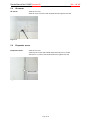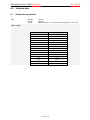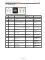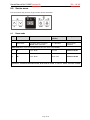
1
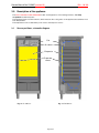
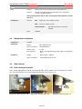
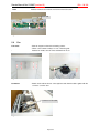
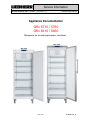
Service Information
After Sales Service International
Service Manual No. 21/2007 (version 01)
LWL/KDT/baj/14.05.07
Appliance Documentation
GKv 5710 / 5760
GKv 6410 / 6460
Refrigerator for the catering business, ventilated
GKv 6460
GKv 5710
Page 1/15
21200701SM_gb
Service Manual No. 21/2007 (version 01)
GKv ..10/..60
Contents
1.0
2.0
3.0
3.1
4.0
4.1
4.2
4.3
Operating and control elements............................................................................................. 3
Functions at a glance.............................................................................................................. 3
Description of the appliance................................................................................................... 4
Sensor positions, schematic diagrams ...................................................................................... 4
Main components and their functions ................................................................................... 5
Electrical components and functions ......................................................................................... 5
Refrigeration components ......................................................................................................... 6
Other features ........................................................................................................................... 6
4.3.1
4.3.2
4.3.3
4.3.4
5.0
5.1
5.2
5.3
5.4
6.0
6.1
7.0
8.0
8.1
8.2
8.3
9.0
Door closing mechanisms ..................................................................................................................... 6
Pressure compensating valve ............................................................................................................... 7
Water drain............................................................................................................................................ 7
Adjustable feet....................................................................................................................................... 7
Assembly instructions / replacement of parts ...................................................................... 8
Electronic control system........................................................................................................... 8
Fan9
Air sensor ................................................................................................................................ 10
Evaporator sensor ................................................................................................................... 10
Technical data ....................................................................................................................... 11
Refrigerator compartment........................................................................................................ 11
Customer menu ..................................................................................................................... 12
Service menu ......................................................................................................................... 13
Demo mode............................................................................................................................. 13
Service mode .......................................................................................................................... 14
Sensor menu ........................................................................................................................... 15
Table of error codes .............................................................................................................. 15
Page 2/15
Service Manual No. 21/2007 (version 01)
1.0
GKv ..10/..60
Operating and control elements
4
6
5
2
3
1
Refrigerator compartment
1 : Temperature display
2 : Temperature setting buttons
3 : Alarm OFF button
4 : Child proofing display
5 : ON/OFF button
6 : Fan switch (if activated, the symbol next to the child's face lights up)
2.0
Functions at a glance
Control:
Electronic control system
Temperature display:
Actual value
Temperature range:
+1°C to +15°C
Temperature alarm:
Visual and audible
Door alarm:
Audible
Floating alarm contact:
Not present
HACCP:
Not present
Fan:
Present
Defrosting:
Automatic
Interior light:
Not present
Service menu:
Present
Compressor:
Standard
Solenoid valve-refrigeration
circuit:
Not present
Door closing mechanism:
Present
Page 3/15
Service Manual No. 21/2007 (version 01)
3.0
GKv ..10/..60
Description of the appliance
The GKv 5710/5760 and GKv 6410/6460 models are refrigerators for the catering business, with freely
suspended rear wall evaporator.
The appliances have a fan in the interior, which increases the cooling action of the appliance and achieves more
even temperatures.
The temperature control is effected by an air sensor and evaporator sensor.
3.1
Sensor positions, schematic diagram
Fan
Air sensor
Evaporator
Evaporator
sensor
Fig. 3.1 / 1: GKv 57..
Fig. 3.1 / 2: GKv 57..
Page 4/15
Service Manual No. 21/2007 (version 01)
GKv ..10/..60
4.0
Main components and their functions
4.1
Electrical components and functions
Electronic control system
Type:
Series 6 electronic control system:
Components:
Integral PCB
Setting range:
+1°C to +15°C
Display range:
+1°C to +47°C
Functions
Ventilation:
Ventilation ON:
Fan in continuous operation
Ventilation OFF:
Fan in parallel with compressor
Note: - When the door is open, the fan is always switched off
- During initial operation the fan does not run before the
evaporator is cooler than +8°C.
Temperature alarm:
When:
Display value longer than 20 minutes 4K warmer than set value.
Audible:
4 beeps (suppressed during initial operation).
Visual:
Flashing temperature display.
To avoid unnecessary warnings (e.g. door opening), the temperature has to be
above the alarm value for at least 20 minutes = alarm delay.
(e.g. set value: +5°C , display for 20 minutes at +9°C
alarm).
Door alarm:
Child proofing:
When:
Door open longer than 3 minutes.
Audible:
3 beeps.
The function is activated via the customer menu (see 7.1).
When the child proofing is activated, the ON/OFF button and the temperature
setting buttons are inactive. The remaining functions can be used.
Defrosting:
Automatic during standstill phase of the compressor.
Sensor
Evaporator sensor:
Air sensor:
Position:
In sensor pocket on back of evaporator.
Function:
- Switches the compressor ON
- Switches the fan ON with a delay when the appliance is put into
operation
Position:
On the left next to the fan, behind the cover.
Function:
- Switches the compressor OFF.
- Generates the display value
Position:
In front panel.
Type:
Reed PCB
Switch
Door switch:
Contact type: Make contact
Function:
Activation via magnet in the door, magnet is non-replaceable.
Switching signal when:
door closed:
fan
door open:
fan
door alarm
Page 5/15
ON
OFF
ON
Service Manual No. 21/2007 (version 01)
GKv ..10/..60
Loads
Fan:
Position:
At the centre back of the ceiling of the compartment liner.
Function:
Provides even temperatures and increases the cooling action
(see also Ventilation function)
During initial operation the fan does not start before the evaporator is cooler
than +8°C.
Compressor:
Function:
ON:
Evaporator sensor switch-on value.
OFF:
Air sensor switch-off value.
Special features:
Type:
4.2
On-delay time (8 mins.) must have
elapsed.
Standard
Refrigeration components
Compressor:
Standard
Evaporator:
Design:
Rear wall evaporator.
Type of installation:
Suspended freely.
Injection point:
Top left
Condenser:
4.3
Flow sequence:
Down on the right-hand side and up again on the left-hand
side
Design:
Wire-on-tube condenser
Type of installation:
Suspended freely at the rear
Other features
4.3.1 Door closing mechanisms
At an opening angle between 0 and 90°, the hinge bush slides over the oblique curve of the hinge bolt so that the
door closes automatically. At an opening angle larger than 90°, the door stays open.
Fig. 4.3.1/ 1 Opening angle > 90°
Fig. 4.3.1/ 2 Opening angle < 90°
Page 6/15
Fig. 4.3.1/ 3 Opening angle = 0°
Service Manual No. 21/2007 (version 01)
GKv ..10/..60
4.3.2 Pressure compensating valve
The pressure compensating valve is situated behind the fan cover in the rear wall.
Pressure compensating valve
Fig. 4.3.2 / 1
4.3.3 Water drain
The water drain has a ¾" thread on the underside to allow hose connection, if required.
Fig. 4.3.3 / 1
4.3.4 Adjustable feet
The adjustable feet are screwed on from underneath with an Allen screw. A reinforcing bracket is screwed into
place for each of the two rear adjustable feet to increase their stability.
Fig. 4.3.4/ 1 Adjustable foot
Fig. 4.3.4/ 2 Reinforcement for rear adjustable foot
Page 7/15
Service Manual No. 21/2007 (version 01)
GKv ..10/..60
5.0
Assembly instructions / replacement of parts
5.1
Electronic control system
Covers:
Unclip covers on the underside of the front housing.
Fig. 5.1/ 1
Fig. 5.1./ 2
Bolt:
Undo screw and remove bolt.
Bolt
Fig. 5.1 / 3
PCB carrier:
PCB carrier
PCB edge
connectors
Fig. 5.1/ 4
- Draw front housing forwards and lift it up.
- Remove PCB edge connector and unclip PCB carrier from the front housing.
Front panel
Lock
Fig. 5.1./ 5
Page 8/15
Service Manual No. 21/2007 (version 01)
PCB:
GKv ..10/..60
Release marked locks and remove PCB from the PCB carrier.
Reed PCB
Fig. 5.1 / 6
5.2
Fan
Fan cover:
-
Fig. 5.2/ 1 Fan cover
Connector:
- Remove stoppers and undo the fastening screws.
- Tilt the cover forwards and lay it on one of the wire grids.
Release fan holder, remove vanes and detach fan motor
Fig. 5.2/ 2 Fan holder
- Detach strain relief at the rear of the appliance and draw the cable together with the
connector out of the duct
Connector for fan cable
Fig. 5.2 / 3
Page 9/15
Service Manual No. 21/2007 (version 01)
5.3
GKv ..10/..60
Air sensor
Air sensor:
- Remove fan cover
- Remove sensor from the holder and extricate it through the rear wall.
Fig. 5.3 / 1
5.4
Evaporator sensor
Evaporator sensor:
- Remove fan cover.
- Undo bayonet screws and carefully swivel the evaporator to the left.
- Pull sensor out of the pocket and extricate it through the rear wall.
Sensor pocket
Fig. 5.4 / 1
Page 10/15
Service Manual No. 21/2007 (version 01)
6.0
Technical data
6.1
Refrigerator compartment
Fan:
Wattage:
Voltage:
Speed:
GKv ..10/..60
14 watts
230 volts
1800 rpm Direction of rotation: right (viewing direction: onto shaft)
Sensor values:
Temperature °C
Resistance value kOhm
+35
+30
+25
+20
+15
+10
+5
0
-5
-10
-15
-20
-25
-30
-35
3.1
3.8
4.7
5.9
7.3
9.3
11.9
15.3
19.8
25.9
34.1
45.3
60.8
82.3
112.8
Page 11/15
Service Manual No. 21/2007 (version 01)
7.0
Step
GKv ..10/..60
Customer menu
Display
Operation
Display following
operation
Testing option / Info
Service menu start
1
Actual value
Hold down "Alarm" button for 3
seconds
c
Activation customer
menu
2a
c
Press "Alarm" Changeover
between c and h with "Up"
c0
Child proofing
deactivated
2a
c0
Press "up"
c1
Activate child
proofing
2a
c1
Press first "Alarm", then „On/Off“
Actual value
Child proofing ON
2b
c
Press "Alarm"
c1
child proofing
activated
2b
c1
Press "down"
c0
Deactivate Child
proofing
2b
c0
Press first "Alarm", then „On/Off”
Actual value
Child proofing OFF
3
c
Press "up"
h
Choosing display
brightness
3
h
Press „Alarm“
h1 to h5
Adjust Display
brightness
3
h1 to h5
Select stage of brightness
wanted with "Up" and confirm
with "Alarm"
h
Display brightness
saved
3
h
Press “On/Off”
Actual value
Display brightness
adjusted
Page 12/15
Service Manual No. 21/2007 (version 01)
8.0
GKv ..10/..60
Service menu
The service menu may be used only by customer service technicians.
8.1
Step
Demo mode
Display
Operation
Display following
operation
Testing option / Info
Service menu start
1
Actual value
Hold down "Alarm" and press
"On/Off" at the same time
d1 or d0 flashes
Service menu
activation
Demo mode (Demo mode can be deactivated only via service menu, not by OFF/ON.)
2a
d1
Press "Alarm"
Set value
Demo mode ON
2b
d0
Press "Alarm"
Actual value
Demo mode OFF
Operation is switched to the mode wanted, demo mode or normal, as soon as "Alarm" has been actuated.
Page 13/15
Service Manual No. 21/2007 (version 01)
8.2
Step
GKv ..10/..60
Service mode
Display
Operation
Display following
operation
Testing option /
Info
d1 flashes
Service menu
activation
Service menu start
1
Actual value
Hold down "Alarm" and press
"On/Off" at the same time
Service mode-- Test display LED, buttons, door contact, potentiometer -1
d1
Press "Up" until "L" flashes.
L
Service mode
selected
2
L
Press Alarm
rd
Service mode
activated
3
rd
Door open and closed
All button LEDs and
display segments shine
Door contact, LEDs
4
All button LEDs
and display
segments shine
Press all the buttons
Brief beep – LO lights
up
Buttons
After step 4 actuation of the last button, L0 flashes
Service mode
-- testing electric loads-5
L0
No operation
L0
All OFF
7
LO
Press Alarm
L2
Compressor ON
8
L2
Press Alarm
L7
Fan ON
Return to step 5 is brought about by pressing the "Alarm" button again.
End
Press "On/Off"“
Page 14/15
around
4-star
freezer
evaporator
Service Manual No. 21/2007 (version 01)
compartme
nt with
wound-
8.3
Step
GKv ..10/..60
Sensor menu
Display
Operation
Display following
operation
Testing option / Info
Service menu start
1
Actual value
Hold down "Alarm" and press
"On/Off" at the same time
d1 flashes
Service menu
activation
Demo mode (Demo mode can be deactivated only via service menu, not by OFF/ON.)
1
d1
Press "Up" until "F" flashes.
E
Sensor selection
2a
E
Press "Alarm" and select sensor
with "Up"
E1 and E2 in
alternation with the
respective temperature
Sensor
2b
E9
Open/close door
Displays door status
1 open, 0 closed
Reed contact
As soon as "Alarm" is pressed, you reach the higher-level menu (d1, L, F).
9.0
Table of error codes
Error code
Defective component
Emergency operation
F1
Air sensor
Compressor: 20 min. ON, 15 min. OFF
Fan:
Depending on setting
F2
Evaporator sensor
Compressor: 20 min. ON, 15 min. OFF
Fan:
Depending on setting
Page 15/15