1
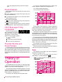
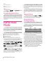
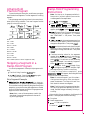
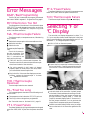
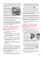
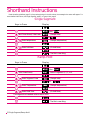
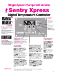
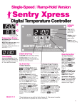
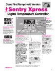
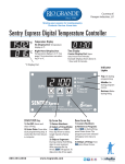
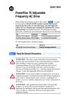
Rio Grande
RG-720 Instruction Manual
°F
°C
Temperature Display
Temperature display is in °F.
Time Display
Temperature display is in °C.
See page 7 for instructions on
selecting °F and °C.
: Separates
hours from minutes. Example:
Display shown above is 1 hour
and 2 minutes.
°C Display Dot
Indicator
Lights
On during
programming.
Program
Review
Hr./Min.
when lit
On during
program review.
Run
°F When Off
°C When Lit
START/
STOP
HIGHER
Blinks dur-
LOWER
SENTRYXpress
MICRO
ing firing.
PROCESSOR
TM
The Sentry Xpress 2.0 micro processor is manufactured by the
Orton Ceramic Foundation and displays the CE mark.
START/STOP Key
firing.
Starts and stops a
Press after
each programming step. It
works like the Enter key on a
computer.
Up Arrow Key
Down Arrow Key
From
press
START. Press Up Arrow to
select a program.
from
or during firing, press Down Arrow.
The program you have selected will appear one
step at a time.
during a User Defined firing, skips to the next segment. After pressing Up
Arrow,
will appear.
To skip, press Up Arrow.
again.
from
Arrow.
press Down
1
Contents
General Guidelines . . . . . . . . . . . . . . . . . 3
Time and Temperature Display . . . . . . . . . . . . . . . . . . . 3
Operation Begins from the
IdLE Display . . . . . . . . . . . . . . . . . . . . . . . . . . . . . . . . . . 3
Thermocouple Inspection . . . . . . . . . . . . . . . . . . . . . . . 3
A Rapid Way to Scroll Numbers . . . . . . . . . . . . . . . . . . 3
Program Review & Repeat Firing . . . . . . . . . . . . . . . . . 3
Delay . . . . . . . . . . . . . . . . . . . . . . . . . . . . . . . . . . . . . . . 3
Rate . . . . . . . . . . . . . . . . . . . . . . . . . . . . . . . . . . . . . . . . 4
Power Failures . . . . . . . . . . . . . . . . . . . . . . . . . . . . . . . . 4
CPLT Message: Firing Completed . . . . . . . . . . . . . . . . 4
Thunder Storms and Power Surges . . . . . . . . . . . . . . . 4
Theory of Operation . . . . . . . . . . . . . . . . 4
Hold . . . . . . . . . . . . . . . . . . . . . . . . . . . . . . . . . . . . . . . . 5
Two Firing Modes: Single Segment and Ramp-Hold . . 5
Single Segment Programming Instructions . . . . . . . . . 5
Temperature Over-Shoot . . . . . . . . . . . . . . . . . . . . . . . . 6
Ramp-Hold Mode. . . . . . . . . . . . . . . . . . . 6
Repeat Firings . . . . . . . . . . . . . . . . . . . . . . . . . . . . . . . . 6
Programming a Cooling Segment. . . . . . . . . . . . . . . . . 6
A Ramp-Hold Practice Program . . . . . . . . . . . . . . . . . . 7
Skipping a Segment in a Ramp-Hold Program . . . . . . 7
Ramp-Hold Programming Instructions. . . . . . . . . . . . . 7
Safety
The warranty on your Sentry Xpress
controller does not cover damage from
overfiring, regardless of the
circumstances. It is the operator’s
responsibility to make sure the kiln turns
off at the proper time.
When the kiln is not in use, disconnect the
power.
Do not leave the kiln unattended, especially
near the expected shut-off time.
Wear firing safety glasses when looking into the
firing chamber of a hot kiln.
Do not touch hot sides of kiln. Keep unsupervised children away.
Install your kiln at least 12 inches from any wall
or combustible surface.
Do not open lid or door until kiln has cooled and
all switches are off.
Lost Wax Burnout . . . . . . . . . . . . . . . . . . 8
Fire only in a well-ventilated, covered and protected area away from combustible materials.
Overview. . . . . . . . . . . . . . . . . . . . . . . . . . . . . . . . . . . . . 8
A Sample Program. . . . . . . . . . . . . . . . . . . . . . . . . . . . . 8
Burnout Instructions. . . . . . . . . . . . . . . . . . . . . . . . . . . . 8
Keep cordset away from hot sides of kiln or furnace.
Error Messages . . . . . . . . . . . . . . . . . . . . 9
BAdP / Bad Programming . . . . . . . . . . . . . . . . . . . . . . . 9
EtH / Electronics Too Hot . . . . . . . . . . . . . . . . . . . . . . . 9
FaIL / Thermocouple Failure . . . . . . . . . . . . . . . . . . . . . 9
TCR / Thermocouple Reversed . . . . . . . . . . . . . . . . . . . 9
FtL / Fired Too Long . . . . . . . . . . . . . . . . . . . . . . . . . . . 9
PF 1 / Power Failure. . . . . . . . . . . . . . . . . . . . . . . . . . . . 9
PF 2 / Power Failure. . . . . . . . . . . . . . . . . . . . . . . . . . . . 9
TcO / Thermocouple Failure . . . . . . . . . . . . . . . . . . . . . 9
Selecting °F or °C Display . . . . . . . . . . . . 9
Display Messages . . . . . . . . . . . . . . . . . 10
Trouble Shooter. . . . . . . . . . . . . . . . . . . 10
Problem: Controller display is blank. No heat in kiln.. 10
Problem: Controller display turns on. No heat in kiln. 11
Problem: Kiln switch box ½ amp fuses keep blowing. 11
©2004, by Paragon Industries, L.P. IM-221/10-04
2 Single Segment/Ramp-Hold
DANGEROUS VOLTAGE! Do not touch heating elements with anything. Disconnect before
servicing.
General
Guidelines
I
A Rapid Way to
Scroll Numbers
The
and
keys change number settings during programming. Ordinarily, you would press
to raise a number and
to lower it. But
sometimes it is faster to press the opposite key. This is because the numbers scroll below 0000 to the highest number,
and vice versa. Examples:
Time and Temperature
Display
Center Dot: Time
A center dot appears during time display. It separates
hours from minutes (i.e. 1
hour, 30 minutes displays as
01.30). During temperature
display, the dot disappears.
The center display dot indicates
time instead of temperature.
°F
Right-Hand Dot: °C
When temperature
is displayed in °C, a dot
appears in the lower
right. In °F display, it
disappears. You can
choose between Fahrenheit and Celsius display. See page 9.
°C
I
To program a 99.59 hour Hold when the display shows
00.00, press the
once.
I
To program a FULL rate when the display shows 0000,
press the
once.
I
To program a temperature of 200°F when the display
shows 1800°F, press the
. That is faster than
pressing the
.
Program Review &
Repeat Firing
Program Review lets you check that the information
programmed into the controller is correct. It is a good habit
to use Program Review before every firing. Program Review shows the values for the program in active memory,
which is—
Operation Begins from the
IdLE Display
The program that was fired last.
must appear before you can fire the kiln.
I
If
,
, or other message appears instead of
when the kiln is first turned on, press the
key (the key with the circular arrow).
will appear.
I
If you press
pear. To get back to
I
If the display shows an error message such as
stead of
, see page 9.
I
(firing completed) appears at the end of a firing.
To make
appear, press
.
during a firing,
, press
Keep shelves, posts and ware 1” - 1 ½” away from the
thermocouple.
will apagain.
in-
Thermocouple Inspection
The small rod protruding into the firing chamber is the
temperature sensor, or thermocouple.
CAUTION: Bumping the thermocouple can push it
out of the firing chamber. This could cause an overfire!
The controller does not contain an alarm to detect this
type of failure. Bumping the thermocouple could also
cause inaccurate readings.
The program that was selected since the last firing.
I
press the
key. The rate, temperature, hold, etc. will display
one after the other. Firing will continue.
I
press the
key. After rate, temperature, hold, etc.,
will appear. Press
.
will appear, and the
kiln will begin firing the program just reviewed.
Delay
Delay is a count-down timer. The kiln begins firing when
the timer runs out of time. Use Delay to fit a firing into your
schedule.
CAUTION: For safety, do not leave the kiln alone during a delay or a firing. We cannot guarantee your kiln
against overfiring even though the controller is automatic.
After you have selected a program and the controller is ready to begin firing,
will appear.
I
A 1/8” diameter thermocouple should extend into the
firing chamber ½” - 5/8”.
Press the
alternating with
key once.
.
will appear,
I
A ¼” diameter thermocouple should extend into the firing chamber 1” or more.
Use the arrow keys to enter delay time. (The decimal
separates hours and minutes. Example: 1 hour 10
minutes = 01.10) Then press
.
will ap-
3
pear, alternating with time left until the firing begins.
Power Failures
After a power failure, the controller will continue firing
provided that:
I
The kiln temperature is above 212°F/100°C when the
power comes back on.
I
The temperature dropped no more than 180°F/100°C
while the power was off.
1) It fires at a controlled heating rate, or speed, measured in degrees of temperature change per hour.
2) It fires to a target temperature.
3) It can hold the target temperature.
Power Failure Messages
The power failed during firing, and temperature
dropped more than 180°F/100°C.
The power failed during firing, and kiln temperature was below 212°F/100°C when the power came back on.
CPLT Message: Firing
Completed
When the firing has successfully completed, the Sentry
Xpress will shut off power to
the elements. Then three messages will cycle one after the other:
(complete)
Firing time in hours and minutes
The current kiln temperature
Thunder Storms and
Power Surges
Unplug the kiln or disconnect the power when the kiln is
not in use, especially during thunder storms and in areas
with frequent power surges. If the kiln is part way through a
firing when a storm begins, it is probably okay to continue
the firing with close supervision. Do not leave the kiln unattended.
Theory of
Operation
The temperature you are firing to is called the target
temperature. After the controller reaches the target temperature, it can also hold that temperature.
The controller fires at a controlled heating rate. The rate
is figured in degrees per hour. If you selected a rate of 100°
per hour, it would take 10 hours for the kiln to reach 1000°.
Rate is similar to “miles per hour.”
In summary, the controller does three basic tasks:
4 Single Segment/Ramp-Hold
The controller fires in segments, or stages. A segment is
a given heating rate to a target temperature. Shown in the
left column is a segment with a target temperature of 1250°
and a rate of 625°, with a hold of one hour.
Heating rate is figured in degrees per hour. The recommended heating rate for the material you are firing is usually available from your supplier. It also varies depending
on the thickness of the material.
To figure how long a firing segment will take, subtract
the current temperature from the target temperature and
divide the resultant temperature by the heating rate. In the
diagram above, the firing time is 1250° - 80° (room temperature) = 1170 ÷625 = 1.87 hours.
The controller can fire up to 8 segments per firing. One
segment is often all that is needed, though.
After the controller has finished firing the last segment,
it will turn off power to the elements.
Rate
Each segment must include a rate, which is degrees of
temperature change per hour.
The kiln will fire at full power when the rate is
1799°F/999°C. Full power displays as
.
Note: To enter full power from
key once.
, press the
Hold
Hold maintains a steady temperature for the length of
time you specify. You can use Hold in both heating up and
cooling down segments.
Single Segment
Programming Instructions
Note: Single Segment firing is all you will ever
need if you are only going to a temperature and
holding.
When Hold is set to 99.59 hours, the controller will remain at that temperature indefinitely, until you press
. To enter a 99.59 hour Hold, press the
once from 00.00 during programming.
From
Note: During firing, the display shows Hold temperature and time left in Hold.
/ (200°F or 111°C)
/ (500°F or 277°C)
To give you greater flexibility, your controller has two
firing modes:
/ (1000°F or 555°C)
/ (1500°F or 833°C)
Single Segment Mode (see next column)
Often times, all you will need is one segment. A single
segment includes rate (temperature change per hour), target temperature, and (if needed) hold time.
/ (Full Power)
Then press
Ramp-Hold Mode (see page 7)
Ramp-Hold mode offers much greater flexibility than
Single Segment mode. Use Ramp-Hold to create custom
firings with up to eight segments. The controller can store
four Ramp-Hold programs in memory. Programs are numbered 1 - 4.
How to Select a Firing Mode
From
display, press
and the hold time from the last firing will
appear (e.g. 1 hour 10 minutes = 01.10). Use the
arrow keys to change the hold time. Then press
.
will appear. Press
to begin firing.
will appear, the Run indicator light with
begin blinking, and the kiln will begin firing.
To stop a firing before completion, press
.
will appear, alternating with kiln
temperature and total firing time.
Note: Do not be concerned if your kiln makes a
clicking sound during firing. Kilns use relays to
power the elements. The relays click each time
their electrical contacts come together.
once.
Press the
key several times. You will see
the following display messages:
Note: The firing speed you select (see step 2) is a
pre-programmed speed. The kiln’s actual firing
speed may be less, depending on the kiln model,
available voltage, and density of load you are firing.
SPd1:
Single Segment, Speed 1 / 200°F/111°C rate per hour
SPd2:
Single Segment, Speed 2 / 500°F/277°C rate per hour
SPd3:
Single Segment, Speed 3 / 1000°F/555°C rate per hour
SPd4:
Single Segment, Speed 4 / 1500°F/833°C rate per hour
SPd5:
Single Segment, Speed 5 / Maximum rate
.
or
and the target temperature from
the last firing will appear. Use the arrow keys to
change the target temperature. Then press
.
In Single Segment mode, you can choose one of five firing speeds. Then enter the temperature you are firing to.
Suggested Firing Mode
Single Segment
Single Segment
Ramp-Hold
Ramp-Hold
Ramp-Hold
Ramp-Hold
.
Use the
key (not the
) to
select a firing rate (temperature rise per hour)
from 1 through 5:
Two Firing Modes: Single
Segment and Ramp-Hold
Type of Firing
Enameling
Silver Clay
Glass Bead Annealing
Glass Fusing
Glass Slumping
Lost Wax
, press
When the kiln fires to completion, the controller will
beep for 30 seconds. The display will show the following:
I
Firing time
I
Present temperature
I
= Fired to completion
To return to
, press
.
PrO1:
Ramp-Hold, Program 1
5
PrO2:
A program can have up to eight segments. You don’t
have to use all eight segments. Use only the number needed
per firing. Often one segment is all you will need. Zero out
the unused segments. The instructions on page 7 explain
how to do that.
Ramp-Hold, Program 2
PrO3:
Ramp-Hold, Program 3
PrO4:
Ramp-Hold, Program 4
(To get back to
, press
times until
appears.)
several
Temperature Over-Shoot
When a kiln is heated too fast, it may over-shoot the target temperature, especially in small kilns at lower temperatures. To avoid this, add an extra segment in a Ramp-Hold
program to slow the firing. The segment with the slower
rate should begin approximately 40° - 60° below the target
temperature.
Ramp-Hold
Mode
You can make your own firing programs and store them
in the controller’s memory. A firing program tells the kiln
how fast to fire, and to what temperature. The simplest program is one segment. You can use up to eight segments with
your controller in Ramp-Hold mode.
Each segment includes a firing rate and firing temperature. You can also soak, or hold, the temperature for a specified period. Each segment stores three details:
I
rate (temperature change in degrees per hour)
I
target temperature
I
hold at the target temperature (not always used)
The controller can retain four programs in memory even
when power is turned off. Programs are numbered 1 - 4.
The first message to appear after you plug in your Sentry
Xpress is
. Press
. Then use the
key
to scroll through these messages:
.
To use Ramp-Hold mode for the first time, select
. You do that by pressing the
key after
appears. Then follow the instructions on page 7 to enter
temperature, heating rate, etc.
is Program 1. When you fire the kiln again, you
can repeat Program 1 by selecting
. When you are
ready to fire a different program, select
, which is
Program 2. Then enter temperatures, heating rates, etc. Select Program 3 and 4 the same way.
6 Single Segment/Ramp-Hold
You can over-write a program by selecting it and entering rates and temperatures again. This automatically
over-writes the previous program. Write down your programs in a notebook and record firing results for each firing.
Repeat Firings
To repeat the last firing, press
from
. The
kiln will begin firing. But first, make sure you are repeating
the correct firing by using Program Review (page 3).
Programming a
Cooling Segment
For controlled cooling, program a segment to a lower
target temperature than that of the preceding segment.
Example: You fire at a rate of 500°F per hour to 1450°F
with your first segment. You want the kiln to cool at a rate
of 100°F per hour down to 700°F. Here is how you would
program the two segments:
Rate
°F/°C
Temp.
°F/°C
Hold
1
500/277
1450/788
00.00
2
100/55
700/371
00.00
Segment
The first segment is the heating segment. The second
one is the cooling segment. The controller does not use minus numbers for cooling. Just enter a lower target temperature than that of the previous segment.
If you prop the lid or door for a fast cooling, program a
fast cooling rate for that segment. If you lower the temperature quickly by propping the lid but program a slow cooling
rate, the controller will just raise the temperature again.
Example: Some glass artists flash-cool the glass just after
it fuses. They open the door a few inches to remove heat,
then close it again. This takes the glass down rapidly
through the devitrification range. To program a flash-cool,
use maximum rate. This shuts off the heating elements during that segment, allowing the kiln to cool rapidly.
Note: During fast cooling, do not open the door all the
way. Do not force-cool the kiln with a fan.
A Ramp-Hold
Practice Program
To practice using the controller, we will enter a program
that includes three segments. The last segment is a cooling
segment.
Ramp-Hold Programming
Instructions
Note: You have up to 8 segments available in
Ramp-Hold. If you don’t need all 8, zero out the
unused segments. See step 6 below.
Using the programming instructions in the next column,
enter the this firing schedule. Then use Program Review
(page 3) to check for accuracy.
From
, press
.
Press the
key (not the
).
and
are
Ramp-Hold programs. When the one you want
appears, press
. (Ignore
.)
will appear. Enter firing rate (temperature
change per hour) for segment 1. 1° = slowest
rate. 1799°F/999°C = full power. Then press
.
PrO1
rA1 = 250
°F 1 = 750
HLd 1 = 00.00
rA2 = 900
°F 2 = 1425
HLd 2 = 00.30
rA3 = 150
°F 3 = 750
HLd 3 = 00.00
rA4 = 0000 (zeroes cancel segments 4-8)
or
and the target temperature from
the last firing will appear. Use the arrow keys to
change the temperature. Then press
.
and the hold time from the last firing will
appear (e.g. 1 hour 10 minutes = 01.10). Use the
arrow keys to change the hold time. Then press
.
Continue entering values for the segments
needed. When
appears for the next segment that you don’t need, select
. Then
press
. This will zero out the remaining
segments. (Example: You need only 1 segment.
When
appears, enter
.)
Skipping a Segment in a
Ramp-Hold Program
You can skip a segment in a Ramp-Hold program as follows:
The kiln is firing. Press the
key.
will appear. Press the
key again.
The firing will skip to the next segment.
will appear. Press
to begin firing.
will appear and the Run indicator light
with begin blinking. The kiln is now firing.
To stop a firing before completion, press
.
will appear, alternating with total
firing time and kiln temperature.
Note: Do not be concerned if your kiln makes a
clicking sound during firing. Kilns use relays to
power the elements. The relays click each time
their electrical contacts come together.
Skip Segment Example
I
You have programmed 1425°F for glass fusing, followed by a segment
for controlled cooling. Watching the glass through the
peephole, you notice that the glass edges have rounded
nicely. Use Skip Segment to end the firing segment and
begin the one for slow cooling.
Note: Make a note of the temperature at which the
glass fused. Program that temperature for the next firing of that type of glass.
Note: The kiln’s actual firing rate may be less than
the rate you programmed, depending on the kiln
model, available voltage, and density of load you
are firing.
When the kiln fires to completion, it will beep for 30
seconds. The display will show the following:
I
Firing time
I
Present temperature
I
= Fired to completion
To return to
, press
.
7
Lost Wax
Burnout
Segment 3 lowers temperature to 800°F/426°C, the typical casting temperature for silver. (Most types of gold cast
at 900°F/482°C.)
CAUTION: Only kilns with vent holes are designed
for lost wax burnout. However, you can use a kiln without the vent hole provided that you open the door ½”
during venting.
CAUTION: Always use a wax tray.
Note: These instructions apply to injection wax that
melts at 200°F, not pattern waxes and plastics that
melt at higher temperatures. If smoke appears during
wax elimination, turn off the kiln. Smoking wax means
the kiln fired hotter than 300°/148°C.
Overview
Lost wax casting is the process of carving a shape in wax ,
and then casting that shape in metal. After the wax has been
carved, a mold is made of the wax shape. The mold is a negative image of the wax. The wax is later melted out of the
mold through hollow channels called sprues.
Lost wax burnout is the process of preparing a casting
mold for the melted metal that will be poured into it. The
steps in lost wax burnout:
Melt the wax from the mold.
Remove wax from the kiln before raising the temperature higher than 300°F/148°C.
Harden the mold at high temperature.
Maintain the mold at the casting temperature recommended for the type of metal that will be
poured into the mold.
CAUTION: Prevent wax or carbon from contacting
the kiln’s walls and elements. Carbon build-up inside a
kiln ruins the interior. Carbon conducts electricity and
causes elements to short circuit. Damage to elements
from contact with foreign materials is not covered by
warranty.
A Sample Program
See your digital controller instruction manual to enter
this program:
Rate
°F/°C
Temp.
°F/°C
Hold
1
500/277
300/148
01.00
2
500/277
1350/732
01.00
3
450/250
800/426
02.00
Segment
Segment 1 heats the wax to 300°F/148°C and holds it for
one hour, allowing it to drip from the mold.
Segment 2 hardens the mold.
8 Single Segment/Ramp-Hold
Note: Casting temperature depends on the size of the
mold. The temperatures above are only a guide. See
your jewelry supply dealer for temperature
recommendations.
Burnout Instructions
Place a metal tray inside the kiln on three ½” posts.
Place the mold on a wire mesh screen on top of the
tray. The mold’s sprue hole should be down. The
tray will catch melting wax as it drips from the
sprue hole.
Keep the kiln’s vent hole(s), if any, open during
wax elimination. If the kiln has no vent hole, leave
the door open ½”. This allows fumes to escape the
kiln. Heat the kiln to 300°F/148°C and hold it at
that temperature for at least one hour.
Note: Do NOT heat the wax above 300°F/148°C. Hold
at 300°F/148°C for at least one hour. During this hour,
the wax will melt from the mold and drip into the tray. If
the kiln gets hotter than 300°F/148°C, the wax may
smoke and deposit carbon inside your kiln, causing expensive damage.
After one hour at 300°F/148°C, open the kiln. Remove the mold and wax tray. Pour the wax from the
tray and leave the tray out of the kiln until your
next wax elimination. (Do not leave the tray in the
kiln!)
Heat the mold to the temperature recommended
by your jewelers’ supply house where you purchased the mold material. This is usually around
1350°F/732°C.
Lower the temperature to the casting temperature
of the metal. Hold at that temperature until you
are ready to begin casting. Remove the mold with
tongs. Wear protective gloves and safety glasses.
Saving a Carbon-Damaged Kiln
If you follow the above directions, your kiln should be
safe from wax damage. In some cases, a small amount of
carbon may form on the walls over a period of time. This is
due to the burning of wax residue that was left in the mold.
For this reason we recommend that you periodically fire the
kiln to 1500°F/815°C as follows:
Open the vent cover(s) or leave the door ajar ½”.
Fire the kiln empty to 1500°F/815°C at a rate of
300°F/166°C with a one hour hold (01.00).
Error Messages
BAdP / Bad Programming
The kiln will not fire because the program just entered
has a rate of 0000 in segment 1. Program the firing again.
EtH / Electronics Too Hot
The temperature of the electronic circuit board is above
158°F/70°C. This could damage the controller, so the firing
has been stopped. To prevent this, keep the firing room
cooler. Use better ventilation.
FaIL / Thermocouple Failure
The thermocouple, or temperature sensor, failed during
firing. Causes:
I
Defective thermocouple or disconnected/loose wires
I
Defective controller
I
Electrical noise
PF 2 / Power Failure
The power failed during firing and kiln temperature was
below 212°F/100°C when the power came back on.
TcO / Thermocouple Failure
The thermocouple failed during the
display.
Selecting °F or
°C Display
The controller can display temperature in either °F or
°C. If your controller shows a small display dot in the lower
right corner of the display, the temperature shown is °C. No
dot means °F. To change temperature display:
UNPLUG kiln or disconnect power.
Thermocouple Paperclip
Test
Check the thermocouple wire connections. (See
your kiln instruction manual.) If connections are
tight, perform this test:
UNPLUG the kiln or disconnect the power. Remove the controller. Remove the two thermocouple
wires from the back of the controller.
Cut a thin paperclip in half. Insert a U-shaped
paperclip piece, or other piece of thin wire, where
you removed the thermocouple wires.
Remove the four screws that hold the controller to
the front of the kiln. Carefully remove the controller
from the kiln. Leave wires attached to the controller.
Plug in the kiln. If the controller displays room temperature, replace the thermocouple. If it shows
, replace the controller.
TCR / Thermocouple
Reversed
Thermocouple lead wires are reversed.
FtL / Fired Too Long
This message appears when both of the following conditions are met:
I
The temperature rise is less than 27°F/15°C per hour.
I
The firing is 4 hours longer than programmed.
See “Controller turns on. No heat in kiln,” page 11.
PF 1 / Power Failure
The power failed during firing and temperature dropped
more than 180°F/100°C by the time the power came back
on.
Look at the back of the controller. A plastic jumper
on the back of the board determines the type of temperature display. When the jumper connects two
pin-type terminals, display reads °F. When the
jumper is removed, display reads °C. Remove or insert the jumper as desired. (You can purchase the
jumper from a computer supply store if necessary.)
Install the controller being careful not to jar components on the back of the controller against the kiln
case.
9
Display
Messages
Trouble Shooter
Problem: Controller display is
blank. No heat in kiln.
The firing was stopped.
I
Is the kiln connected to the power?
Fired to completion. If the kiln is already hotter than the
programmed target temperature when you begin firing,
will appear immediately after you begin firing.
I
Has the circuit breaker tripped or fuse blown?
I
(page 3) Delay is a count-down timer that starts the
kiln when the time runs out.
Is power reaching the wall receptacle?
Test with a voltmeter or test light if you are not sure.
I
Has the kiln switch box ½ amp fuse blown?
or
(and temperature) (pages 5, 7) The target
temperature (the temperature that the kiln will fire to). Each segment has a target temperature.
Full power firing rate. At this setting the kiln will fire at
its fastest rate. There are two ways to select full power:
1) Select
in Single Segment mode.
2) Select a rate of 1799°F/999°C at the
prompt in
Ramp-Hold mode. A fast way to do this is to press the
key once from
.
will appear.
(pages 4, 5, 7) Hold time of a segment, shown in hours
and minutes. (i.e. 2 hours 15 minutes = 02.15.)
(page 3) The controller is ready for you to enter a program or to begin a repeat firing.
Firing has begun. A moment after
will hear the relay(s) clicking.
appears, you
(pages 5, 6, 7) These are
Ramp-Hold programs stored in memory.
(page 4) Select this option to program a custom firing.
etc. (Rate) (page 7) This appears in
Ramp-Hold programming for each segment. 1, 2, etc. are segment numbers. Enter the rate of temperature change for that
segment. Rate is figured in degrees of temperature change per
hour. Example:
A temperature rise of 100° in two hours = 50° rate.
A temperature drop of 200° in one hour = 200° rate.
(page 5) These
are firing rates, or speeds, in Single Segment mode.
(Skip Step) (page 7) This message appears when you
press the
key during a Ramp-Hold firing. If you press
the
key again, the firing will skip to the next segment.
The firing was stopped by pressing
.
The “Ready to Start” message appears after programming a firing. Press
to begin firing.
10 Single Segment/Ramp-Hold
The kiln’s ½ amp fuse is
located in the kiln switch
box. Remove by pressing the
fuse holder and turning
counter-clockwise half a
turn. Check the fuse by placing the probes of an ohmmeter on the ends of the fuse. If
the ohmmeter reads less
than an ohm (digital meter)
or reads 0 ohms (analog meter), the fuse is okay. If the
reading is OPEN (digital meter) or infinity/no needle
movement (analog meter), the fuse is bad. Replacement
fuse:
AGC 1/2 A 250V AC
I
Is the controller receiving power? Test the power INPUT connections on the back of the controller with a
voltmeter.
Controller Power Input
Test
Unplug the kiln. Remove the 4 screws holding
the controller faceplate to
the switch box. Lift faceplate out of box and let the
board hang on the box
with the back of the board
facing you. Plug the kiln
back in. Touch voltmeter
probes (in AC mode) to
both INPUT connections (the white and orange wires).
CAUTION: Do not let the back of the board touch a
grounded object. Make sure the voltmeter is in the AC
mode when placing the probes on INPUT connections.
Controller Power Input Test Result: No voltage
UNPLUG kiln. Check the switch box for disconnected
wires between the cord, transformer, and controller. If wiring is okay, replace the transformer.
Controller Power Input Test Result: 20 - 24 volts AC
Correct current is reaching the board from the transformer. But since the board is not lighting up, it is probably
defective. Return the controller for repair or replacement.
Controller Power Input Test Result: less than 20 volts
Did you recently replace the transformer? It may be the
wrong voltage. The voltage is below 20, which is not enough
power for the controller. To find out the cause of low voltage, continue below:
Controller Input Test #2
The back of the board is
still facing you and the kiln
is plugged in. Remove the
INPUT plug, which is the
white, orange, and blue
wires, from the back of the
controller. Touch a voltmeter probe to the white
wire and the other probe to the orange wire.
Input Test #2 Result: Less than 20 Volts AC
There are two possible reasons: 1) Low voltage at the
wall receptacle; 2) defective transformer. If wall receptacle
voltage is correct, replace the transformer.
Input Test #2 Result: 20 - 24 Volts AC
The transformer is sending correct voltage to the controller. Yet when the INPUT plug was connected to the
controller, voltage was less than 20. This means the controller is draining the voltage and is defective. Return the controller for repair or replacement.
Problem: Controller display
turns on. No heat in kiln.
I
Is the relay making its normal clicking sound?
Yes, the relay is clicking.
Test the elements with an ohmmeter:
Element Resistance Test
UNPLUG kiln/disconnect the power. Open the
kiln’s switch box. Make sure the wires connecting
the relay to the elements are secure. If connections
are okay, continue to step 2:
Touch the ohmmeter leads to the two element connectors of each element. A no-needle-movement
reading on an analog meter, or OPEN on a digital
meter, indicates a broken element.
If the elements check out okay, replace the relay.
Note: To replace relay, see your kiln’s instruction and
service manual.
switch box. Lift faceplate out of box and let the controller hang on the outside of the box with the back
of the board facing you. Then plug the kiln back in.
Program the controller to fire to 1000°F at FULL
rate in Ramp-Hold mode. Press
.
Put the voltmeter in DC mode. (It must be in DC
mode when testing OUTPUT voltage.) Touch
probes to the red wire and black wire connections.
Measure voltage when the relay clicks on.
Output Test Result: No voltage at red and black wires
The controller is not sending power to the relay. Return
the controller for repair or replacement.
Output Test Result: 10 - 14 v. at red and black wires
The controller is sending correct power to the relay. Unplug kiln/disconnect power. Remove the kiln switch box.
Look for disconnected wires between the controller, relay
and elements. Check the wiring diagram to be sure wires
are connected to the correct terminals. Be sure connections
are tight. If the wiring is okay, replace the relay.
Note: To replace relay, see your kiln’s instruction and
service manual.
Problem: Kiln switch box ½
amp fuses keep blowing.
I
What size fuse are you using? Correct fuse:
AGC ½ A 250V AC.
If the fuse is the correct size, perform the following test:
Kiln Switch Box ½ Amp Fuse Power Test
UNPLUG the kiln/disconnect the power. Remove
the 4 screws holding the controller board faceplate
to the switch box. Lift faceplate out of box and let the
board hang on the
outside of the box
with the back of the
board facing you.
Then plug the kiln
back in. Disconnect
both wire plugs from
the back of the controller. Apply power to kiln. If fuse blows, replace
the transformer. (If the fuse does not blow, the
problem is a board or relay. Go to step 2.)
We know the controller is receiving voltage, because the
display is lit. But the voltage from the transformer may be
too low to power the relays. Perform the “Controller Power
Input Test,” page 10. If your controller passes the input test,
perform the “Controller Power Output Test”:
Connect the INPUT plug (orange, blue, and white
wires) to the board again. Leave off the OUTPUT
wire plug (the one with the red, green and black
wires). Program the controller to fire to 1000°F at
FULL rate in Ramp-Hold mode. Press
. If
the fuse blows, replace or service the board. (If the
fuse does not blow, the problem is caused by a short
in the coil of a relay. Go to step 3.)
Controller Power Output Test
Is the controller sending voltage to the relay? Test OUTPUT with a voltmeter:
UNPLUG kiln/disconnect power. Reconnect the
OUTPUT wire plug. Reinstall the board in the
switch box. Replace the relay.
No, the relay is not clicking.
UNPLUG the kiln/disconnect the power. Remove
the 4 screws holding the controller faceplate to the
11
Shorthand Instructions
Read the safety guidelines, page 2. After pressing the keys in the left column, the message in the center will appear. For
more detailed instructions, see Single Segment, page 5, or Ramp-Hold, page 6.
Single Segment
Keys to Press
Display
thru
(Not Down Arrow) Select rate
(Sample rate)
or
Enter temperature
(Sample temperature)
Enter hold time
(Or hold time)
The kiln is now firing.
Ramp-Hold
Keys to Press
Display
thru
(Not Down Arrow)
Enter Segment 1 rate
Select Program #1, 2, 3, or 4
(Sample rate)
or
Enter Temperature
(Sample temperature)
Enter Hold Time
(Or hold time)
First segment not needed: enter a rate of 0000.
The kiln is now firing.
12 Single Segment/Ramp-Hold