1
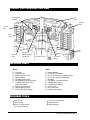
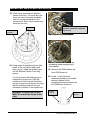
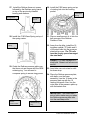
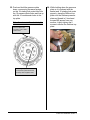
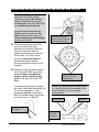
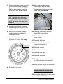
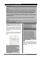
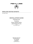
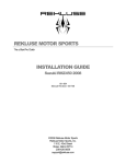
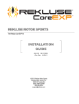
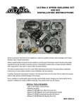
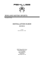
REKLUSE MOTOR SPORTS The z-Start Pro Clutch INSTALLATION GUIDE BMW650 191-600 Manual Revision: 121307 ©2002 Rekluse Motor Sports Rekluse Motor Sports, Inc. 110 E. 43rd Street Boise, Idaho 83714 208-426-0659 [email protected] TABLE OF CONTENTS 2 z-START PRO CROSS-SECTION VIEW 3 INCLUDED PARTS 3 REQUIRED TOOLS 3 BIKE PREPARATION AND DISASSEMBLY 4 INSTALLING THE z-START PRO CENTER CLUTCH 5 INSTALLING THE CLUTCH PACK 5 INSTALLING THE Z-START PRO CLUTCH 6 DETERMINE THE INSTALLED GAP OF THE Z-START PRO CLUTCH 9 SETTING CLUTCH CABLE SLACK 11 APPENDIX A – CENTER CLUTCH REMOVAL TIP SHEET 12 z-Start Pro Installation Guide 2 Z-START PRO CROSS-SECTION VIEW Rotating Hub Assembly Top Plate Pressure Plate Friction Disk Drive Plate Retaining Ring Flat Washer Needle Bearing Flat Washer Center Clutch Stock Throw-out Throw-out Spacer INCLUDED PARTS Item Top Plate Pressure Plate Rekluse Center Clutch Retaining Ring (8) RMS Friction Disks (8) RMS Measured Drive Plates (1) RMS 0.065” Drive Plate (Adjustment Plate) Rotating Hub Assembly Rekluse Spring Carrier Rekluse Throw-out Spacer Item Needle Bearing (2) Flat Thrust Washers (27) 7/16” Chrome Steel Ball Bearings (18) 7/16” Tungsten Carbide Ball Bearings (10) M4x12 Torx Head Screws C200M4 Wave Spring C150M4 Wave Spring T-20 Torx Bit Blue Loctite 243 Rekluse Wire Gauges REQUIRED TOOLS 8mm socket 10mm socket 27mm or 30mm socket (for center clutch nut) 3 T-20 Torx bit (supplied) Impact Wrench Snap ring pliers z-Start Pro Installation Guide 3 BIKE PREPARATION AND DISASSEMBLY 1. Drain oil. 12. Remove bolts and springs from OEM pressure plate. 2. Remove skid plate (if installed). 13. Remove OEM pressure plate. 3. Remove rear bolts from bash guard (if installed) and rotate forward. 4. Remove left side footpeg. 5. Disconnect header pipe from cylinder head. Be careful to retain gasket located between head pipe and cylinder. 14. Remove OEM clutch throw-out retaining ring with snap ring pliers and set aside. Remove OEM clutch throw-out from the pressure plate and set aside. The snap ring and throw-out will be re-installed. 15. Remove the clutch pack (friction disks and drive plates). 6. Remove shift lever. 7. Remove seat. 8. Remove bolt securing oil line under oil tank. 9. Place oil-suitable container beneath bike. Remove oil line banjo bolt from bottom of case. Be careful to retain the 2 crush washers as they will be re-used. 10. Remove clutch actuator arm. 11. Remove clutch cover and rotate forward to allow clear access to clutch components. You will slightly rotate the oil line towards the rear tire allowing you to pull the side case cover away from the motor. 4 16. Remove the OEM center clutch hub following the steps outlined in the vehicle manufacturer’s service manual. Retain the OEM Lock washer. Also, see the center clutch removal tip sheet (Appendix A) for further assistance. 17. Retain OEM thrust washer located between OEM clutch basket and OEM center clutch hub. NOTE: thrust washer may be stuck to bottom of OEM center clutch hub. z-Start Pro Installation Guide 4 INSTALLING THE Z-START PRO CENTER CLUTCH 18. Install the Rekluse Center Clutch with the OEM thrust washer behind it on top of the basket. 19. Install the OEM lock washer on top of the Rekluse Center Clutch. 20. Install center clutch nut and torque to the specified torque value found in the manufacturer’s service manual. 21. Bend washer up against a face of the center clutch nut. INSTALLING THE CLUTCH PACK 22. You will use the 8 Rekluse friction disks with 8 Rekluse steel drive plates. To start, you will use (6) x 0.065” and (2) x 0.048”. The top steel drive plate must be a 0.065”. Install 1 Rekluse steel drive plate onto the Rekluse Center Clutch. Install the Rekluse friction disks with a Rekluse steel drive plate between each one. See chart for specific model configuration. Top of Pack Rekluse Friction disk ***0.065 Rekluse Steel Drive Plate*** Rekluse Friction disk 0.048 Rekluse Steel Drive Plate Rekluse Friction disk 0.048 Rekluse Steel Drive Plate Rekluse Friction disk 0.065 Rekluse Steel Drive Plate Rekluse Friction disk 0.065 Rekluse Steel Drive Plate Rekluse Friction disk 0.065 Rekluse Steel Drive Plate Rekluse Friction disk 0.065 Rekluse Steel Drive Plate Rekluse Friction disk 0.065 Rekluse Steel Drive Plate Last Plate In First Plate In Bottom of pack 5 z-Start Pro Installation Guide 5 INSTALLING THE Z-START PRO CLUTCH 23. Place lower assembly into Rekluse center clutch hub. You must align the three cut-outs in the lower assembly with the corresponding tabs in the center clutch. Note: some models only have two cut-outs. Scalloped end of ring correctly oriented: clockwise in relation to square end. Cut-outs Rekluse lower assembly Threading retaining ring into groove 24. Using a pair of mechanics gloves (the edges of the ring can be sharp and may cut you), install the retaining ring into the Rekluse Center Clutch ring groove. You must ensure the retaining ring is snapped into the groove. Start the square end of the ring and thread the ring into the groove as shown, ensuring that the scalloped end of the ring is clockwise in relation to the square end. WARNING: Scalloped end of ring MUST be oriented as shown aboveright. 6 Use a screwdriver to ensure the ring is seated by sliding along the ring’s inner diameter. 25. Remove the OEM washers etc. from OEM throw-out. 26. Install 1 of the flat thrust washers followed by the needle bearing followed by the remaining flat thrust washer onto the OEM clutch throw-out. Needle Bearing Flat Thrust Washers z-Start Pro Installation Guide 6 27. Install the Rekluse throw-out spacer followed by the Rekluse spring carrier on top of the previously installed bearing and washers. Spring Carrier 30. Install the C200 wave spring on top of rotating hub into the locating pocket. C200 Wave Spring Throwout Spacer 28. Install the C150 Wave Spring on top of the spring carrier. C150 Wave Spring 31. Place a small amount of oil into the ball grooves of the Rekluse Pressure Plate. 32. Away from the bike, install the 18 tungsten carbide (TC) balls and 9 of the steel balls into the pressure plate ball grooves. The TC balls must be evenly spaced amongst the steel balls. Pattern: 6 TC balls followed by 3 steel balls. Repeat until all grooves are full. 29. Guide the Rekluse pressure plate over the throw-out and secure with the OEM retaining ring. You will need to compress spring to access ring groove. 33. Lean bike over onto stand or with tie-down strap. 34. Place the Rekluse pressure plate, with balls, over the lower assembly. Line the 10 holes in the pressure plate up with the 10 rotating hub posts. Also, line the outer tabs of the pressure plate up with the basket slots. IMPORTANT: The basket has 2 sets of slots, make sure you index the Rekluse pressure plate tabs into the main/deep slots. Rekluse Pressure Plate 7 OEM Retaining Ring z-Start Pro Installation Guide 7 35. Push and hold the pressure plate down, overcoming the wave springs, so the 10 rotating hub posts index into the 10 pressure plate holes and line up with the 10 countersunk holes in the top plate. Note: An extra set of hands is helpful. Pressure plate tabs located in main “deep” basket slots. 36. While holding down the pressure plate so it is indexed with the basket and 10 rotating hub posts properly, place the Rekluse top plate over the Rekluse pressure plate and thread in 2 torx head screws180 across from one another. Lightly tighten the 2 screws to secure the Rekluse top plate. Rotating hub posts indexed into pressure plate holes and lined up with top plate holes. 8 z-Start Pro Installation Guide 8 DETERMINE THE INSTALLED GAP OF THE Z-START PRO CLUTCH Note: Installed gap is measured using two no-go wire gauges. Therefore, if gauges do not slide between Rekluse pressure plate and the pads of the top friction disk, your installed gap is correct. If gauges do slide between the Rekluse pressure plate and the pads of the top friction disk, you need to adjust your installed gap according to step 39. Try to slide wire gauges between pressure plate and pads of top friction disk. 37. Verify that top-most friction disk moves up and down freely between the Pressure Plate and top-most steel drive plate by pulling up and down on top-most friction disk. If no “float” exists, top-most steel drive plate has become disoriented during previous step and needs to be reinstalled. 38. Attempt to slide the shorter legs of the 2 included 0.050” no-go wire gauges between the Rekluse pressure plate and the friction pads of the top friction disk 180° apart. If clutch pack wear exists, gauges will slide in with slight resistance. Do not force the gauges in, if the gauges do not slide in smoothly then the Installed Gap is good and you can move on to Step 40. Attempt to slide both gauges in 180° apart simultaneously NOTE: The gauges need to slide in past the “relief” point on the underside of the pressure plate to get an accurate measurement. Pressure Plate Relief Point Use the small leg of wire gauges. Gauges go past relief point here 9 z-Start Pro Installation Guide 9 39. If the wire gauges slide in smoothly, the clutch pack needs adjustment. Swap the remaining thicker 0.065” Rekluse drive plate for one of the 0.048” thick drive plates. Repeat step 38. 44. Align clutch actuator arm so it points slightly past top dead center (i.e. toward rear of bike). Rotate forward and connect clutch cable. See photo below. Note: The adjustment drive plate is .065”. Once this drive plate has been used, and the clutch wears enough so the wire gauges slide in again, the friction disks need to be replaced. 40. Install the remaining 8 torx head screws using blue Loctite 243 and torque to 14 in-lbs (1.58 Nm). 41. Remove the 2 screws originally installed without Loctite, apply Loctite and torque. 42. Align the teeth of the clutch throwout at 3 o’clock. See image below. 3 o’clock Clutch Actuator Arm 45. Re-install oil line banjo bolt with the 2 OEM crush washers. 46. Re-install bolt that secures oil line under oil tank. 47. Re-install shift lever. 48. Re-install exhaust gasket if it was removed during step 5. 49. Re-install exhaust. 50. Re-install left side footpeg. 51. Re-install bash plate. 52. Re-install skid plate. 53. Fill oil compartment with oil. Refer to OEM manual for recommended volume. 54. Stand the bike upright and reconnect the clutch cable to the lever. 43. Re-install clutch cover. IMPORTANT: SEE NEXT PAGE OF INSTRUCTIONS FOR PROPER CABLE SLACK SETTING 55. Adjust the cable slack for the z-Start Pro (SEE NEXT PAGE). 10 z-Start Pro Installation Guide 10 SETTING CLUTCH CABLE SLACK IMPORTANT: Cable slack adjustment is critical. The cable slack must be adjusted properly and maintained frequently. Failure to do so will result in clutch failure. Adjusting cable slack is different with a z-Start Pro Clutch installed. Cable slack adjustment requires starting the motor in neutral and revving to a minimum of 4500 RPMs (approximately ½-throttle) while checking for lever free play. There must be clutch lever free play while holding a minimum of 4500 RPMs. If there is not enough cable slack, the clutch will slip excessively causing the clutch to fail. Too much cable slack reduces the ability to disengage the clutch at higher RPMs. WARNING: Ensure the bike is in neutral or it could lunge forward unexpectedly when revving the engine. Place the bike into neutral and start the engine. While holding a minimum of 4500 RPMs, check for 1/2" (1cm) of play at the end of the clutch lever before you feel significant resistance. Adjust cable slack accordingly using stock cable slack adjuster(s). In other words, when revving the engine, clutch lever free play should feel like stock. Tip: Use one finger with light pull when checking for lever free play. This will make it easier to distinguish between the light resistance of the lever return spring and the significant resistance felt when disengaging the Rekluse pressure plate. 11 Note: Be sure to review the included Break-in and Maintenance Guide for clutch pack wear adjustments. WARNING: After a 20 minute break-in period, the clutch plates will seat in and you must remeasure the Installed Gap to guarantee the Installed Gap is within the prescribed range— make drive plate adjustments if necessary. Clutch break-in remeasurement of the Installed Gap is necessary whenever new clutch plates are installed. Refer to the “Safety Warnings” and “Break-in Tuning and Maintenance Guide” before operating the z-Start Pro clutch. z-Start Pro Installation Guide 11 APPENDIX A – CENTER CLUTCH REMOVAL TIP SHEET The following covers 3 methods for removing the OEM center clutch from your motorcycle or ATV. At no time should you ever pry against the standoffs of the OEM center clutch because they are easily broken. Note: If your bike has an external tab lock washer, use a flat blade screwdriver to pry the tabs away from the nut. Next use a hammer and punch to lightly tap the tabs flat. 1. Pneumatic or electric impact gun: Place the bike in gear and remove the nut 2. Clutch Holding Tool: Example: Motion Pro # 08-0008 Use the clutch holding tool to hold the center clutch while using a wrench to remove the center clutch nut. 3. Holding the Rear Brake: th th Place the bike in 4 or 5 gear (a higher gear gives you more mechanical advantage). Apply the rear brake firmly and hold firmly while using a wrench to remove the center clutch nut. A second set of hands is helpful. 12 z-Start Pro Installation Guide 12