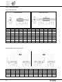
1
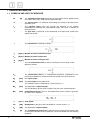
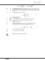
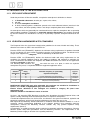
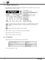
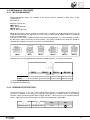
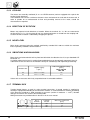
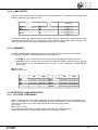
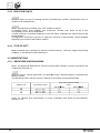
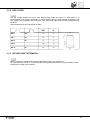
SUMMARY Chapter Description Chapter 1 General information . . . . . . . . . . . . . . . 2 3 Description Atex motors . . . . . . . . . . . . . . . . . . . 44 1.1 Symbols and units of measure . . . . . . . . . 2 3.1 Symbols and units of measurement . . . . . . 44 1.2 Introduction to the Atex directives . . . . . . . . 4 3.2 General characteristics . . . . . . . . . . . . . 45 1.2.1 Explosive atmosphere . . . . . . . . . . . . . 4 3.2.1 Production range . . . . . . . . . . . . . . . 45 1.2.2 European harmonised Atex standards . . . . . 4 3.2.2 1.2.3 Levels of protection for the various categories of equipment . . . . . . . . . . . . 5 Directives 73/23/EEC (LVD) and 89/336/EEC (EMC) . . . . . . . . . . . . 45 3.2.3 Standards. . . . . . . . . . . . . . . . . . . 45 1.2.4 Definition of groups (EN 1127-1). . . . . . . . 5 3.2.4 Product identification . . . . . . . . . . . . . 46 1.2.5 Declaration of conformity . . . . . . . . . . . 6 3.2.5 Tolerances . . . . . . . . . . . . . . . . . . 46 1.3 Use, installation and maintenance. . . . . . . . 6 1.4 Selecting the type of equipment . . . . . . . . . 7 3.3 Mechanical features . . . . . . . . . . . . . . 47 3.3.1 Motor mounting . . . . . . . . . . . . . . . . 47 3.3.2 Degree of protection . . . . . . . . . . . . . 47 3.3.3 Cooling . . . . . . . . . . . . . . . . . . . . 48 3.3.4 Direction of rotation . . . . . . . . . . . . . . 48 3.3.5 Noise level . . . . . . . . . . . . . . . . . . 48 3.3.6 Vibrations and balancing . . . . . . . . . . . 48 1.4.1 Selection procedure . . . . . . . . . . . . . . 7 1.4.2 Selecting a gearmotor . . . . . . . . . . . . . 7 1.4.3 Gear unit with motor fitting . . . . . . . . . . . 8 1.4.4 Speed reducer with solid input shaft . . . . . . 8 1.4.5 Post-selection checks . . . . . . . . . . . . . 9 1.4.6 Operating conditions for Atex-specified equipment . . . . . . . . . . . . . . . . . . . 9 3.3.7 Terminal box . . . . . . . . . . . . . . . . . 48 1.4.7 Service factor - [ Fs ] . . . . . . . . . . . . . 10 3.3.8 Cable entry . . . . . . . . . . . . . . . . . . 49 3.3.9 Bearings . . . . . . . . . . . . . . . . . . . 49 2 Worm gear units for potentially explosive atmospheres . . . . . . . . . . . . . . . . . . . 11 2.1 Construction of Aex-specified equipment . . . 11 2.2 Versions and mounting positions. . . . . . . . 12 2.2.1 2.2.2 2.3 VF Series . . . . . . . . . . . . . . . . . . . 12 W Series . . . . . . . . . . . . . . . . . . . 13 Ordering numbers . . . . . . . . . . . . . . . 14 2.3.1 Variants of gear unit . . . . . . . . . . . . . 14 2.3.2 Options . . . . . . . . . . . . . . . . . . . . 14 2.3.3 Variants of electric motor . . . . . . . . . . . 15 3.4 Electrical characteristics . . . . . . . . . . . . 49 3.4.1 Voltage / frequency . . . . . . . . . . . . . . 49 3.4.2 Isulation class. . . . . . . . . . . . . . . . . 50 3.4.3 3.5 Type of duty . . . . . . . . . . . . . . . . . 50 Modifications . . . . . . . . . . . . . . . . . . 50 3.5.1 Vibrations and balancing . . . . . . . . . . . 50 3.5.2 Drip cover. . . . . . . . . . . . . . . . . . . 51 3.5.3 3.6 Second shaft extension. . . . . . . . . . . . 51 Motor rating charts . . . . . . . . . . . . . . . 52 2.4 Lubrication . . . . . . . . . . . . . . . . . . . 15 3.6.1 BN - Ex II 2D 125°C (1500 min-1) . . . . . . . 52 2.5 Admissible overhung loads. . . . . . . . . . . 17 3.6.2 M - Ex II 2D 125°C (1500 min-1) . . . . . . . 52 3.7 Motors dimensions . . . . . . . . . . . . . . . 53 2.5.1 Radial loads . . . . . . . . . . . . . . . . . 17 2.5.1.1 Calculating the resulting overhung load . . . 17 3.7.1 BN - IMB14 . . . . . . . . . . . . . . . . . . 53 2.5.1.2 Overhung loading verification. . . . . . . . . 18 3.7.2 BN - IMB5. . . . . . . . . . . . . . . . . . . 53 2.5.1.3 Load location factor. . . . . . . . . . . . . . 18 2.5.2 Thrust loads An1, An2 . . . . . . . . . . . . . 18 2.6 Gearmotor rating charts . . . . . . . . . . . . 19 2.7 Rating charts . . . . . . . . . . . . . . . . . . 24 2.8 Motor combinations . . . . . . . . . . . . . . 28 2.8.1 3.7.3 3.8 M . . . . . . . . . . . . . . . . . . . . . . . 54 Declaration of conformity . . . . . . . . . . . . 55 Hybrid imputs . . . . . . . . . . . . . . . . . 29 2.9 Dimensions . . . . . . . . . . . . . . . . . . . 30 2.10 Accessories . . . . . . . . . . . . . . . . . . 42 2.11 Declaration of conformity . . . . . . . . . . . . 43 Revisions Refer to page 56 for the catalogue revision index. Visit www.bonfiglioli.com to search for catalogues with up-to-date revisions. 1 1 GENERAL INFORMATION 1.1 SYMBOLS AND UNITS OF MEASURE An [N] The admissible thrust load represents the force which can be applied axially to the gear unit’s shaft, along with the rated radial load. fS - The service factor is a coefficient representing the severity of the duty for the operating cycle. fTP - The adjusting factor takes into account the influence of the ambient temperature in calculating the computational torque. This factor is relevant for worm gear units. i - The gear ratio is expressed as the relationship of the input shaft speed to the output shaft speed. I - The intermittence is defined as follows: Jc [Kgm2] Moment of inertia of the driven load. Jm [Kgm2] Moment of inertia of the motor. JR [Kgm2] Moment of inertia of the gear unit. K - The load acceleration factor is used to calculate the service factor, and is defined as follows: KR - The transmission factor is a computational parameter, proportional to the tension generated by an external transmission keyed to the gear unit shaft. M2 [Nm] Net output torque Mn2 [Nm] The rated torque at the output shaft. The catalogue value is calculated for a service factor fS= 1. Mr2 [Nm] The application’s required torque . This should always be less than or equal to the gear unit’s rated torque Mn2. Mc2 [Nm] Computational torque. This is a virtual parameter used to select the gear unit, by means of the equation: n 2 [min-1] Shaft speed. Pn1 [kW] Rated power at the input shaft, calculated for a service factor fS = 1. PR [kW] The application’s required power . RC [N] The computational radial load is generated by an external transmission and, for the input and output shafts respectively, can be calculated from the following equations: The admissible radial load should always be more than or equal to the computational radial load. The point value is given in the catalogue for each unit’s gear frame size and transmission ratio, and refers to the shaft’s centre line. RN [N] S - ta [°C] tf [min] The operating time is the total duration of the work cycle phases. tr [min] The rest time is the interval of no work between two phases. Zr - Number of starts per hour. ηd - The dynamic efficiency is expressed as the ratio between the power measured at the output shaft and that applied to the input shaft: The safety factor is defined as follows: Ambient temperature. [ ]1 This value refers to the input shaft. [ ]2 This value refers to the output shaft. Danger. May cause slight injury to persons. 3 1.2 INTRODUCTION TO THE ATEX DIRECTIVES 1.2.1 EXPLOSIVE ATMOSPHERE Under the provisions of Directive 94/9/EC, an explosive atmosphere is defined as a mixture: a. b. c. d. of flammable substances, whether gas, vapour, mist or dust; with air; in certain atmospheric conditions; in which, following ignition, combustion spreads to the entire unburned mixture (note that in the case of dust, the entire quantity of dust is not always completely burnt after combustion). An atmosphere which may potentially be transformed into an explosive atmosphere due to operating and/or ambient conditions is defined as a potentially explosive atmosphere. The products governed by Directive 94/9/EC are intended for use only in a potentially explosive atmosphere defined in this way. 1.2.2 EUROPEAN HARMONISED ATEX STANDARDS The European Union has issued two harmonisation guidelines in the area of health and safety. These directives are known as ATEX 100a and ATEX 137. Directive ATEX 100a (EU/94/9/EC) stipulates the minimum safety requirements for products intended for use in explosion risk areas within the member countries of the European Union. The directive also assigns such equipment to categories, which are defined by the directive itself. Directive ATEX 137 (EU/99/92/EC) defines the minimum health and safety requirements for the workplace, for working conditions and for the handling of products and materials in explosion risk areas. The directive also divides the workplace into zones and defines the criteria for the application of product categories in said zones. The following table describes the zones into which the user of a plant, in which an explosive atmosphere may occur, is required to divide the equipment application areas. Zones Gaseous Dusty atmosphere atmosphere G D 0 1 20 21 2 22 Formation frequency of a potentially explosive atmosphere Type of danger Present continuously or for long periods Likely to occur in normal operation occasionally Not likely to occur in normal operation but if it does occur will persist for short period only Permanent Potential Minimal BONFIGLIOLI RIDUTTORI gear units selectedin this catalogue are suitable for installation in zones 1, 21, 2 and22, as highlightedin grey in the above table. Electric motors described in this catalogue are certified in category 2D (125°C max. temperature) and therefore suitable for installation in zones 21 and 22. As from 1 July 2003 the ATEX directives come into force throughout the entire European Union, and replace existing conflicting national and European laws on explosive atmospheres. It should be emphasised that, for the first time, the directives also govern mechanical, hydraulic and pneumatic equipment, and not only electrical equipment as has been the case so far. With regard to the Machinery Directive 98/37/EC it should be noted that directive 94/9/EC is a set of extremely specific requirements dedicated to the dangers deriving from potentially explosive atmospheres, whereas the Machinery Directive contains only very general explosion safety requirements (Annex I). Consequently, as regards protection against explosion in potentially explosive atmospheres, Directive 94/9/EC (ATEX 100a) takes precedence over the Machinery Directive. The requirements of the Machinery Directive apply to all other risks regarding machinery. 4 1.2.3 LEVELS OF PROTECTION FOR THE VARIOUS CATEGORIES OF EQUIPMENT The various categories of equipment must be able to operate in conformity with the Manufacturer’s operational specifications, at certain defined levels of protection. Category Protection Group Group level I II Very high M1 Very high High 1 Type of protection Operating conditions Two independent means of protection or safety capable of operating even when two independent faults occur Two independent means of protection or safety capable of operating even when two independent faults occur Protection suitable for normal operation and heavy duty conditions M2 High 2 Protection suitable for normal operation and frequent faults or equipment in which malfunction is normal. Normal 3 Protection suitable for normal operation The equipment remains powered and operational even in the presence of an explosive atmosphere The equipment remains powered and operational in zones 0, 1, 2 (G) and/or zones 20, 21, 22 (D) Power to the equipment is shut off in the presence of a potentially explosive atmosphere The equipment remains powered and operational in zones 1, 2 (G) and/or zones 21, 22 (D) The equipment remains powered and operational in zones 2 (G) and/or 22 (D) 1.2.4 DEFINITION OF GROUPS (EN 1127-1) Group I Applies to equipment intended for use underground in parts of mines and those parts of surface installations of such mines, liable to be endangered by firedamp and/or combustible dust. Group II Applies to equipment intended for use in other places liable to be endangered by explosive atmospheres. BONFIGLIOLI RIDUTTORI products may not therefore be installed in mines, classified in Group I and in Group II, category 1. To summarise, the classification of equipment into groups, categories and zones is illustrated in the table below, whereby the availability of BONFIGLIOLI RIDUTTORI products is highlighted in grey. II I Group mines, firedamp Category Atmosphere(1) Zone Type of protection gear unit Type of protection motor (1) M1 other potentially explosive areas (gas, dust) M2 1 2 3 G D G D G D 0 20 1 21 2 22 c, k c, k c, k c, k d, e IP6X + temp.max n(A) IP5X o IP6X + temp. max G = gas D = dust This catalogue describes BONFIGLIOLI RIDUTTORI gear units and gearmotor, intended for use in potentially explosive atmospheres, with limitation to categories 2 and 3. The products described herein conform to the minimum safety requirements of European Directive 94/9/EC, which is part of the directives known as ATEX (ATmosphères EXplosibles). 5 1.2.5 DECLARATION OF CONFORMITY The Declaration of Conformity, a copy of which is available in this catalogue, is the document which attests to the conformity of the product to Directive 94/9/EC. The validity of the Declaration is bound to observance of the instructions given in the User, Installation and Service Manual for safe use of the product throughout its service life. The instructions regarding ambient conditions are of particular importance inasmuch as failure to observe them during operation of the product renders the certificate null and void. In case of doubt regarding the validity of the certificate of conformity, contact the BONFIGLIOLI RIDUTTORI technical department. 1.3 USE, INSTALLATION AND MAINTENANCE The instructions for safe storage, handling and use of the product are given in the unit’s User, Installation and Service Manual. This can be downloaded from www.bonfiglioli.com/atex.html where the manual is available in PDF format in a number of languages. This document must be kept in a suitable place, in the vicinity of the installed gear unit, as a reference for all persons authorised to work with or on the product throughout its service life. The Manufacturer reserves the right to modify, supplement or improve the Manual, in the interests of the User. 6 1.4 SELECTING THE TYPE OF EQUIPMENT 1.4.1 SELECTION PROCEDURE: Determine the application service factor fS in relation to the type of load (K factor), number of starts per hour Zr and hours of operation per day. Now determine the power required at the motor shaft: The efficiency value « ηd » can be determined as follows (approximately): Worm gear unit efficiency - n1=1400 The selection procedure now depends on the type of gear unit, as follows: a. gear unit equipped with IEC motor fitting b. gear unit equipped with solid input shaft. Proceed as follows: 1.4.2 SELECTING A GEARMOTOR a. Determine service factor fs as formerly specified. b. Determine power required at gearbox input shaft: c. Consult the gearmotor rating charts and locate the table corresponding to normalised power Pn: 7 Unless otherwise specified, power Pn of motors indicated in the catalogue refers to continuous duty S1. For motors used in conditions other than S1, the type of duty required by reference to CEI 2-3/IEC 34-1 Standards must be mentioned. For duties from S2 to S8 in particular and for motor frame 132 or smaller, extra power output can be obtained with respect to continuous duty. Accordingly the following condition must be satisfied: The adjusting factor fm can be obtained from table here after. 1.4.3 GEAR UNIT WITH MOTOR FITTING - with reference to the rating charts, identify the gear unit which, for the required speed n2, provides a rated power Pn1 such that: - Select an electric motor rated: - Finally, check that the motor/gear unit combination generates a safety factor equal to or greater than the service factor for the application in question, in other words: - If the selected gear unit is of type C112, C212 or C312 with ratio i > 40 ,operating with a number of hourly starts Z > 30 ,correct the service factor taken from the graph by a factor of 1.2. Finally, check that the recalculatedservice factor fs still satisfies the condition S ı fs. 1.4.4 SPEED REDUCER WITH SOLID INPUT SHAFT - Calculate the value of the computational torque: ftp Helical gear units C, A, F, S Worm gear units VF, W Type of load ftp = 1 8 K1 uniform load K2 moderate shock load K3 heavy shock load Ambient temperature [°C] 20° 30° 40° 1.00 1.00 1.06 1.00 1.02 1.12 1.00 1.04 1.17 - for the speed n2 closest to that required, select the gear unit with a rated torque Mn2 equal to or greater than the computational torque Mc2, in other words: 1.4.5 POST-SELECTION CHECKS Once the gear unit or gearmotor has been selected, we recommend checking the selection as follows: Momentary peak torque The momentary peak torque is of the order of 200% of the rated torque Mn2. Check that the point value of the peak torque satisfies this condition and equip the installation with a torque limiter if necessary. Radial load The catalogue gives the values of the maximum admissible radial load for both the input shaft « Rn1 » and the output shaft « Rn2 ». These values refer to a load applied at the shafts’ centre lines and must always be greater than the actually applied load. See paragraph: Radial loads. Thrust load Check that the thrust component of the load does not exceed the maximum admissible value as given in the paragraph: Thrust loads. 1.4.6 OPERATING CONDITIONS FOR ATEX-SPECIFIED EQUIPMENT Ambient temperature -20°C < to < +40°C. The gear unit must be installed in the mounting position specified in the order and given on the nameplate. Any deviation from this requirement must be approved in advance by BONFIGLIOLI RIDUTTORI. Do not under any circumstances install the gear unit with its shaft in an inclined orientation, unless previously authorised to do so by the BONFIGLIOLI RIDUTTORI Technical Service Department. The speed of the motor mounted to the gear unit must not exceed n = 1500 min-1. Should the gearbox be connected to an inverter driven motor the latter must be explicitly suitable for the purpose and used in full compliance with the instructions set forth by the manufacturer. Under no circumstances the setting of the inverter shall allow the motor to exceed the maximum speed permitted (1500 min-1) or overload the gearbox itself. All the instructions in the User Manual (www.bonfiglioli.com/atex.html) regarding installation, use and routine maintenance of the unit must be followed in full. 9 1.4.7 SERVICE FACTOR - [ fs ] This factor is the numeric value describing reducer service duty. It takes into consideration, with unavoidable approximation, daily operating conditions, load variations and overloads connected with reducer application. In the graph below, after selecting proper “daily working hours” column, the service factor is given by intersecting the number of starts per hour and one of the K1, K2 or K3 curves. K_ curves are linked with the service nature (approximately: uniform, medium and heavy) through the acceleration factor of masses K, connected to the ratio between driven masses and motor inertia values. Regardless of the value given for the service factor, we would like to remind that in some applications, which for example involve lifting of parts, failure of the reducer may expose the operators to the risk of injuries. If in doubt, please contact our Technical Service Department. Acceleration factor of masses - [K] This parameter serves for selecting the right curve for the type of load. The value is given by the following ratio: where: Jc moment of inertia of driven masses referred to motor shaft Jm moment of inertia of motor 10 2 WORM GEAR UNITS FOR POTENTIALLY EXPLOSIVE ATMOSPHERES 2.1 CONSTRUCTION OF ATEX-SPECIFIED EQUIPMENT Equipped with service plugs for periodic lubricant level checks. Factory-charged with lubricant, depending on the mounting position specified in the order. (*) Viton® seal rings as standard. Side surfaces machined and tapped provide for extra mounting flexibility. No plastic component parts. Nameplate indication of the product category and type of protection. (*) With the exception of gear units: W110_P(IEC) in mounting positions V5 and V6 and W110_HS in position B3, V5 and V6. 11 2.2 VERSIONS AND MOUNTING POSITIONS 2.2.1 VF SERIES 1 - 2 Flange location 12 2.2.2 W SERIES 1 - 2 Flange location 13 2.3 ORDERING NUMBERS 2.3.1 VARIANTS OF GEAR UNIT W 75 U D30 60 P80 B5 B3 2D3D-130 OPTIONS MOUNTING POSITION B3 (Default), B6, B7, B8, V5, V6 MOTOR MOUNTING B5, B14 INPUT CONFIGURATION P56 P63 VF P71 P80 P71 P80 P90 W P100-P112 P132 HS HS GEAR RATIO OUTPUT SHAFT BORE W 75 D30: default ; D28: option VERSION GEAR FRAME SIZE VF: 30, 44, 49 ; W: 63, 75, 86, 110 PRODUCT SERIES: VF, W = worm gearbox 2.3.2 OPTIONS The applicability of the various options is indicated in the technical data tables according to the specific configuration and gear ratio. 14 2D3D-160 The gear unit can be installed in zones 21 and 22 (categories 2D and 3D). The unit’s surface temperature is less than 160°C. 2D3D-130 The gear unit can be installed in zones 21 and 22 (categories 2D and 3D). The unit’s surface temperature is less than 130°C. 2G3G-T3 The gear unit can be installed in zones 1 and 2 (categories 2G and 3G). The temperature class is T3 (max. 200 °C). 2G3G-T4 The gear unit can be installed in zones 1 and 2 (categories 2G and 3G). The temperature class is T4 (max. 135 °C). 2.3.3 VARIANTS OF ELECTRIC MOTOR BN 71B 4 230/400-50 2D CLF B5 W ... OPTIONS RC Drip cover RV Improved balancing PS Double shaft extension TERMINAL BOX POSITION W (default), N, E, S MOTOR MOUNTING B5, B5R, B14, B14R INSULATION CLASS CL F standard CL H option DEGREE OF PROTECTION 2D (Ex II 2D 125°C) VOLTAGE - FREQUENCY 230/400-50 POLE NUMBER 4 MOTOR SIZE 63A - 100LB (IEC motor) MOTOR TYPE BN = IEC 3-phase 2.4 LUBRICATION The gear units are factory-charged with long-life synthetic lubricant in the quantity suitable for the mounting position specified in the order. For transportation purposes these units are equipped with closed filler plugs. A vented plug, which the User must replace before putting the unit into service, is supplied along with each unit. For a preliminary oil level check, insert a dipstick in the yellow filler plug opening as specified in the unit’s User Manual. Lubricant charge [litres] for VF gear units: B3 B6 B7 B8 V5 VF 30 VF 44 VF 49 0.045 0.075 0.12 0.045 0.075 0.12 0.045 0.075 0.12 0.045 0.075 0.12 0.045 0.075 0.12 V6 0.045 0.075 0.12 Tivela oil S 320 15 Lubricant charge [litres] for W gear units B3 B6 B7 i= W63 W75 W86 W110* 7, 10, 12, 15 19, 24, 30, 38, 45, 64 7, 10, 15 30, 40 20, 25, 50, 60, 80, 100 7, 10, 15 30 20, 23, 40, 46, 56, 64, 80, 100 input P80...P132 HS 7 İ i İ 15 HS 20 İ i İ 100 0.31 0.38 0.48 0.52 0.56 0.64 0.73 0.90 B3 1.50 1.50 2.70 0.31 0.38 0.48 0.52 0.56 0.64 0.73 0.90 B6 1.65 1.65 1.65 0.31 0.38 0.48 0.52 0.56 0.64 0.73 0.90 B7 1.65 1.65 1.65 0.31 0.38 0.48 0.52 0.56 0.64 0.73 0.90 B8 1.90 1.90 1.90 V5 V6 0.31 0.38 0.48 0.52 0.56 0.64 0.73 0.90 V5 1.70 1.70 1.70 0.31 0.38 0.48 0.52 0.56 0.64 0.73 0.90 V6 1.60 1.60 1.60 *Worm gears type W110 and WR110 configured for mounting positions B3, V5 and V6 will be supplied unlubricated. Tivela oil S 320 Filling/breather plug Level plug W 63, W 75, W86 Drain plug B3 B6 B7 B8 V5 V6 16 W 110 2.5 ADMISSIBLE OVERHUNG LOADS 2.5.1 RADIAL LOADS 2.5.1.1 CALCULATING THE RESULTING OVERHUNG LOAD External transmissions keyed onto input and/or output shaft generate loads that act radially onto same shaft. Resulting shaft loading must be compatible with both the bearing and the shaft capacity. Namely shaft loading (Rc1 for input shaft, Rc2 for output shaft), must be equal or lower than admissible overhung load capacity for shaft under study (Rn1 for input shaft, Rn2 for output shaft). OHL capability listed in the rating chart section. In the formulas given below, index (1) applies to parameters relating to input shaft, whereas index (2) refers to output shaft. The load generated by an external transmission can be calculated with close approximation by the following equation: Kr = 1 Kr = 1.25 Kr = 1.5 - 2.0 M [Nm] d [mm] 17 2.5.1.2 OVERHUNG LOADING VERIFICATION 2.5.1.3 LOAD LOCATION FACTOR VF 30 VF 44 VF 49 W 63 W 75 W 86 W 100 a b c 60 71 99 132 139 149 173 45 51 69 102 109 119 136 1 1 1 1 1 1 1 2.5.2 THRUST LOADS An1, An2 Permissible thrust loads on input [An1] and output [An2] shafts are obtained from the radial loading for the shaft under consideration [Rn1] and [Rn2] through the following equation: The thrust loads calculated through these formulas apply to thrust forces occurring at the same time as rated radial loads. In the only case that no overhung load acts on the shaft the value of the admissible thrust load [An] amounts to 50% of rated OHL [Rn] on same shaft. Where thrust loads exceed permissible value or largely prevail over radial loads, contact Bonfiglioli Riduttori for an in-depth analysis of the application. 18 2.6 GEARMOTOR RATING CHARTS 0.12 kW n2 min-1 M2 Nm S i Rn2 N 18.7 21.8 21.8 28.5 29.1 36 37 47 47 55 66 73 87 94 131 131 187 34 31 30 26 25 21 21 17.4 17.4 15.7 13.5 12.4 9.8 9.9 7.0 7.3 5.1 1.4 1.0 1.5 1.2 1.7 2.0 1.4 1.7 2.4 2.8 2.2 3.5 1.0 2.9 1.4 3.9 2.0 70 60 60 46 45 36 35 28 28 24 20 18 15 14 10 10 7 3270 2770 3110 2550 2840 2650 2340 2180 2450 2330 1960 2130 950 1750 840 1570 750 VF49_ 70 P63 BN63A4 VF44_ 60 P63 BN63A4 VF49_ 60 P63 BN63A4 VF44_ 46 P63 BN63A4 VF49_ 45 P63 BN63A4 VF49_ 36 P63 BN63A4 VF44_ 35 P63 BN63A4 VF44_ 28 P63 BN63A4 VF49_ 28 P63 BN63A4 VF49_ 24 P63 BN63A4 VF44_ 20 P63 BN63A4 VF49_ 18 P63 BN63A4 VF30_ 15 P63 BN63A4 VF44_ 14 P63 BN63A4 VF30_ 10 P63 BN63A4 VF44_ 10 P63 BN63A4 VF30_ 7 P63 BN63A4 0.18 kW n2 min-1 M2 Nm S i Rn2 N 18.9 22.0 29.3 37 38 47 47 55 66 73 94 94 132 132 132 189 189 50 45 38 31 31 26 26 23 20 18.5 14.8 14.6 10.4 10.9 10.9 7.6 7.8 1.0 1.0 1.2 1.4 1.0 1.2 1.6 1.9 1.5 2.3 2.0 2.9 1.0 2.7 3.8 1.3 3.7 70 60 45 36 35 28 28 24 20 18 14 14 10 10 10 7 7 3150 3000 2750 2570 2260 2110 2380 2270 1900 2070 1700 1920 790 1530 1730 710 1360 VF49_ 70 P63 BN63B4 VF49_ 60 P63 BN63B4 VF49_ 45 P63 BN63B4 VF49_ 36 P63 BN63B4 VF44_ 35 P63 BN63B4 VF44_ 28 P63 BN63B4 VF49_ 28 P63 BN63B4 VF49_ 24 P63 BN63B4 VF44_ 20 P63 BN63B4 VF49_ 18 P63 BN63B4 VF44_ 14 P63 BN63B4 VF49_ 14 P63 BN63B4 VF30_ 10 P63 BN63B4 VF44_ 10 P63 BN63B4 VF49_ 10 P63 BN63B4 VF30_ 7 P63 BN63B4 VF44_ 7 P63 BN63B4 19 0.25 kW n2 min-1 M2 Nm S i Rn2 N 13.2 13.2 13.2 16.5 16.5 20.6 20.6 22.0 26.4 29.3 35 37 44 47 55 55 66 73 94 94 132 132 189 189 99 107 112 85 93 79 71 71 61 55 48 44 40 36 33 34 28 26 21 20 15.2 15.2 10.9 10.9 1.3 2.0 4.0 2.1 2.8 3.6 1.8 2.8 3.6 2.2 2.5 1.0 3.0 1.2 1.4 3.5 1.1 1.7 1.4 2.1 1.9 2.8 2.7 3.8 100 100 100 80 80 64 64 60 50 45 38 36 30 28 24 24 20 18 14 14 10 10 7 7 6200 7000 8000 6200 7000 7000 4730 6200 5960 4250 4040 2480 3750 2300 2200 3500 1830 2020 1650 1870 1480 1690 1320 1510 W75_ 100 P71 BN71A4 W86_ 100 P71 BN71A4 W110_ 100 P71 BN71A4 W75_ 80 P71 BN71A4 W86_ 80 P71 BN71A4 W86_ 64 P71 BN71A4 W63_ 64 P71 BN71A4 W75_ 60 P71 BN71A4 W75_ 50 P71 BN71A4 W63_ 45 P71 BN71A4 W63_ 38 P71 BN71A4 VF49_ 36 P71 BN71A4 W63_ 30 P71 BN71A4 VF49_ 28 P71 BN71A4 VF49_ 24 P71 BN71A4 W63_ 24 P71 BN71A4 VF44_ 20 P71 BN71A4 VF49_ 18 P71 BN71A4 VF44_ 14 P71 BN71A4 VF49_ 14 P71 BN71A4 VF44_ 10 P71 BN71A4 VF49_ 10 P71 BN71A4 VF44_ 7 P71 BN71A4 VF49_ 7 P71 BN71A4 0.37 kW n2 20 min-1 M2 Nm S i Rn2 N 13.7 17.1 17.1 21.4 21.4 22.8 24.5 27.4 30 30 34 36 46 57 72 76 91 98 98 137 137 196 196 152 122 132 112 101 101 101 88 87 78 74 69 57 48 40 37 32 29 29 22 22 15.5 15.5 1.4 1.5 1.9 2.5 1.2 2.0 3.0 2.5 3.9 1.5 3.4 1.7 2.1 2.5 3.0 1.2 3.7 1.0 1.5 1.3 1.9 1.9 2.6 100 80 80 64 64 60 56 50 46 45 40 38 30 24 19 18 15 14 14 10 10 7 7 7000 6200 7000 7000 4480 6060 7000 5730 7000 4040 5370 3850 3590 3360 3130 1910 2920 1550 1780 1400 1610 1250 1440 W86_ 100 P71 BN71B4 W75_ 80 P71 BN71B4 W86_ 80 P71 BN71B4 W86_ 64 P71 BN71B4 W63_ 64 P71 BN71B4 W75_ 60 P71 BN71B4 W86_ 56 P71 BN71B4 W75_ 50 P71 BN71B4 W86_ 46 P71 BN71B4 W63_ 45 P71 BN71B4 W75_ 40 P71 BN71B4 W63_ 38 P71 BN71B4 W63_ 30 P71 BN71B4 W63_ 24 P71 BN71B4 W63_ 19 P71 BN71B4 VF49_ 18 P71 BN71B4 W63_ 15 P71 BN71B4 VF44_ 14 P71 BN71B4 VF49_ 14 P71 BN71B4 VF44_ 10 P71 BN71B4 VF49_ 10 P71 BN71B4 VF44_ 7 P71 BN71B4 VF49_ 7 P71 BN71B4 0.55 kW n2 min-1 M2 Nm S i Rn2 N 13.8 17.3 17.3 17.3 21.6 21.6 23.0 24.6 24.6 27.6 30 31 35 35 36 46 46 55 58 69 73 92 99 115 138 138 197 236 201 180 195 171 166 148 149 153 129 128 115 110 114 101 84 88 76 71 63 59 47 43 39 32 33 23 1.9 2.3 1.0 1.3 3.1 1.7 1.3 2.0 3.9 1.7 2.7 1.0 2.3 2.9 1.2 1.4 3.1 3.3 1.7 4.0 2.0 2.5 1.0 3.1 1.3 3.7 1.8 100 80 80 80 64 64 60 56 56 50 46 45 40 40 38 30 30 25 24 20 19 15 14 12 10 10 7 8000 8000 6200 7000 8000 7000 5770 7000 8000 5480 7000 3790 5160 7000 3620 3400 4750 4490 3200 4200 2990 2800 1660 2630 1510 2490 1360 W110_ 100 P80 BN80A4 W110_ 80 P80 BN80A4 W75_ 80 P80 BN80A4 W86_ 80 P80 BN80A4 W110_ 64 P80 BN80A4 W86_ 64 P80 BN80A4 W75_ 60 P80 BN80A4 W86_ 56 P80 BN80A4 W110_ 56 P80 BN80A4 W75_ 50 P80 BN80A4 W86_ 46 P80 BN80A4 W63_ 45 P80 BN80A4 W75_ 40 P80 BN80A4 W86_ 40 P80 BN80A4 W63_ 38 P80 BN80A4 W63_ 30 P80 BN80A4 W75_ 30 P80 BN80A4 W75_ 25 P80 BN80A4 W63_ 24 P80 BN80A4 W75_ 20 P80 BN80A4 W63_ 19 P80 BN80A4 W63_ 15 P80 BN80A4 VF49_ 14 P80 BN80A4 W63_ 12 P80 BN80A4 VF49_ 10 P80 BN80A4 W63_ 10 P80 BN80A4 VF49_ 7 P80 BN80A4 0.75 kW n2 min-1 M2 Nm S i Rn2 N 14.0 17.5 21.9 21.9 23.3 25.0 25.0 28.0 30 30 35 35 47 47 47 56 58 61 70 70 74 93 93 317 270 229 223 200 201 206 174 172 174 147 153 114 118 117 102 96 96 85 86 79 65 64 1.4 1.7 2.3 1.3 1.0 1.5 2.9 1.3 2.0 3.4 1.7 2.2 1.1 2.3 3.0 2.4 1.3 3.3 2.9 3.7 1.5 3.8 1.9 100 80 64 64 60 56 56 50 46 46 40 40 30 30 30 25 24 23 20 20 19 15 15 8000 8000 8000 7000 5450 7000 8000 5190 7000 8000 4920 7000 3180 4550 7000 4320 3010 7000 4050 7000 2840 3730 2670 W110_ 100 P80 BN80B4 W110_ 80 P80 BN80B4 W110_ 64 P80 BN80B4 W86_ 64 P80 BN80B4 W75_ 60 P80 BN80B4 W86_ 56 P80 BN80B4 W110_ 56 P80 BN80B4 W75_ 50 P80 BN80B4 W86_ 46 P80 BN80B4 W110_ 46 P80 BN80B4 W75_ 40 P80 BN80B4 W86_ 40 P80 BN80B4 W63_ 30 P80 BN80B4 W75_ 30 P80 BN80B4 W86_ 30 P80 BN80B4 W75_ 25 P80 BN80B4 W63_ 24 P80 BN80B4 W86_ 23 P80 BN80B4 W75_ 20 P80 BN80B4 W86_ 20 P80 BN80B4 W63_ 19 P80 BN80B4 W75_ 15 P80 BN80B4 W63_ 15 P80 BN80B4 21 0.75 kW n2 min-1 M2 Nm S i Rn2 N 117 140 200 200 52 44 31 32 2.3 2.7 1.3 3.6 12 10 7 7 2510 2390 1280 2150 W63_ 12 P80 BN80B4 W63_ 10 P80 BN80B4 VF49_ 7 P80 BN80B4 W63_ 7 P80 BN80B4 1.1 kW n2 min-1 M2 Nm S i Rn2 N 17.5 21.9 25.0 25.0 30 30 35 35 35 47 47 56 61 61 70 70 74 93 93 93 117 140 140 200 396 336 294 303 252 255 216 225 228 173 171 150 143 142 125 126 115 96 96 93 77 65 66 46 1.2 1.6 1.0 2.0 1.3 2.3 1.2 1.5 2.9 1.6 2.1 1.7 3.8 2.3 2.0 2.5 1.0 2.6 3.4 1.3 1.6 1.9 3.5 2.5 80 64 56 56 46 46 40 40 40 30 30 25 23 23 20 20 19 15 15 15 12 10 10 7 8000 8000 7000 8000 7000 8000 4540 7000 8000 4230 7000 4040 8000 7000 3810 6840 2580 3530 6290 2450 2330 2220 3140 2020 W110_ 80 P90 BN90S4 W110_ 64 P90 BN90S4 W86_ 56 P90 BN90S4 W110_ 56 P90 BN90S4 W86_ 46 P90 BN90S4 W110_ 46 P90 BN90S4 W75_ 40 P90 BN90S4 W86_ 40 P90 BN90S4 W110_ 40 P90 BN90S4 W75_ 30 P90 BN90S4 W86_ 30 P90 BN90S4 W75_ 25 P90 BN90S4 W110_ 23 P90 BN90S4 W86_ 23 P90 BN90S4 W75_ 20 P90 BN90S4 W86_ 20 P90 BN90S4 W63_ 19 P90 BN90S4 W75_ 15 P90 BN90S4 W86_ 15 P90 BN90S4 W63_ 15 P90 BN90S4 W63_ 12 P90 BN90S4 W63_ 10 P90 BN90S4 W75_ 10 P90 BN90S4 W63_ 7 P90 BN90S4 1.5 kW n2 22 min-1 M2 Nm S i Rn2 N 22.0 25.2 31 35 35 47 47 47 56 61 61 71 71 71 94 455 410 346 305 309 235 232 235 203 192 194 171 169 171 126 1.2 1.5 1.7 1.1 2.2 1.2 1.5 3.0 1.2 1.7 2.8 3.3 1.5 1.9 0.9 64 56 46 40 40 30 30 30 25 23 23 20 20 20 15 8000 8000 8000 7000 8000 3870 7000 8000 3720 6850 8000 8000 3530 6580 2200 W110_ 64 P90 BN90LA4 W110_ 56 P90 BN90LA4 W110_ 46 P90 BN90LA4 W86_ 40 P90 BN90LA4 W110_ 40 P90 BN90LA4 W75_ 30 P90 BN90LA4 W86_ 30 P90 BN90LA4 W110_ 30 P90 BN90LA4 W75_ 25 P90 BN90LA4 W86_ 23 P90 BN90LA4 W110_ 23 P90 BN90LA4 W110_ 20 P90 BN90LA4 W75_ 20 P90 BN90LA4 W86_ 20 P90 BN90LA4 W63_ 15 P90 BN90LA4 1.5 kW n2 min-1 M2 Nm S i Rn2 N 94 94 118 141 141 141 201 201 201 130 130 104 87 89 89 64 63 63 1.9 2.5 1.2 1.4 2.6 3.2 3.0 3.9 1.8 15 15 12 10 10 10 7 7 7 3310 6090 2110 2040 2970 5390 2670 4830 1870 W75_ 15 P90 BN90LA4 W86_ 15 P90 BN90LA4 W63_ 12 P90 BN90LA4 W63_ 10 P90 BN90LA4 W75_ 10 P90 BN90LA4 W86_ 10 P90 BN90LA4 W75_ 7 P90 BN90LA4 W86_ 7 P90 BN90LA4 W63_ 7 P90 BN90LA4 2.2 kW n2 min-1 M2 Nm S i Rn2 N 25.2 31 35 47 47 61 61 71 71 71 94 94 94 141 141 201 201 601 507 453 340 344 281 284 250 247 250 190 190 188 131 131 94 93 1.0 1.2 1.5 1.0 2.0 1.1 1.9 2.3 1.0 1.3 1.3 1.7 3.2 1.8 2.2 2.0 2.7 56 46 40 30 30 23 23 20 20 20 15 15 15 10 10 7 7 8000 8000 8000 6850 8000 6380 8000 8000 3060 6150 2920 5750 8000 2670 5130 2420 4620 W110_ 56 P100 BN100LA4 W110_ 46 P100 BN100LA4 W110_ 40 P100 BN100LA4 W86_ 30 P100 BN100LA4 W110_ 30 P100 BN100LA4 W86_ 23 P100 BN100LA4 W110_ 23 P100 BN100LA4 W110_ 20 P100 BN100LA4 W75_ 20 P100 BN100LA4 W86_ 20 P100 BN100LA4 W75_ 15 P100 BN100LA4 W86_ 15 P100 BN100LA4 W110_ 15 P100 BN100LA4 W75_ 10 P100 BN100LA4 W86_ 10 P100 BN100LA4 W75_ 7 P100 BN100LA4 W86_ 7 P100 BN100LA4 3 kW n2 min-1 M2 Nm S i Rn2 N 35 47 61 71 71 94 94 141 141 201 201 618 469 388 341 341 259 256 179 177 127 127 1.1 1.5 1.4 1.7 0.9 1.3 2.3 1.6 3.1 2.0 3.9 40 30 23 20 20 15 15 10 10 7 7 8000 8000 8000 8000 5660 5360 8000 4840 7480 4380 6700 W110_ 40 P100 BN100LB4 W110_ 30 P100 BN100LB4 W110_ 23 P100 BN100LB4 W110_ 20 P100 BN100LB4 W86_ 20 P100 BN100LB4 W86_ 15 P100 BN100LB4 W110_ 15 P100 BN100LB4 W86_ 10 P100 BN100LB4 W110_ 10 P100 BN100LB4 W86_ 7 P100 BN100LB4 W110_ 7 P100 BN100LB4 23 11 Nm VF 30 2.7 - RATING CHARTS Selection example: In zones 21 and 22 with surface temperature limit of 160 °C The gear unit can be installed In zones 1 and 2 with temperature class limit T3 (200 °C) In zones 21 and 22 with surface temperature limit of 130 °C In zones 21 and 22 with surface temperature limit of 160 °C The gear unit can be installed In zones 1 and 2 with temperature class limit T4 (135 °C) In zones 1 and 2 with temperature class limit T3 (200 °C) hd min -1 Mn2 Pn1 % % Nm kW Rn2 N VF 30_7 200 69 84 10 0.25 630 VF 30_10 140 64 81 10 0.18 770 VF 30_15 93 56 76 10 0.13 910 VF 30_20 70 51 73 10 0.10 1030 VF 30_30 47 41 65 10 0.08 1200 VF 30_40 35 36 60 10 0.06 1340 VF 30_60 23 29 51 11 0.05 1540 VF 30_70 20.0 26 48 11 0.05 1600 24 n1 = 1400 min-1 2D3D-160 — 2G3G-T3 hs 2D3D-130 — 2G3G-T4 n2 n 1 = 1400 min -1 Mn 2 Pn1 Nm kW Rn 1 N Rn2 N 30 Nm VF 44 n 1 = 1400 min -1 min -1 Mn2 Pn1 Pn1 % Nm kW Rn2 N Mn 2 % Nm kW Rn 1 N Rn2 N VF 44_7 200 71 86 29 0.71 1070 29 0.71 200 1070 VF 44_10 140 66 84 29 0.51 1310 29 0.51 220 1310 VF 44_14 100 60 81 29 0.37 1540 29 0.37 220 1540 VF 44_20 70 55 77 30 0.29 1760 30 0.29 220 1760 VF 44_28 50 45 71 30 0.22 2030 30 0.22 220 2030 VF 44_35 40 42 68 30 0.18 2200 30 0.18 220 2200 VF 44_46 30 37 63 30 0.15 2300 30 0.15 220 2300 VF 44_60 23.3 32 58 30 0.13 2300 30 0.13 220 2300 VF 44_70 20.0 30 55 29 0.11 2300 29 0.11 220 2300 2D3D-160 — 2G3G-T3 n1 = 1400 min-1 2D3D-130 — 2G3G-T4 hd 2D3D-160 — 2G3G-T3 hs 2D3D-130 — 2G3G-T4 n2 48 Nm n2 min -1 VF 49 hs hd n1 = 1400 min-1 n 1 = 1400 min -1 Mn2 Pn1 Pn1 % Nm kW Rn2 N Mn 2 % Nm kW Rn 1 N Rn2 N 41 1.00 1140 41 1.00 400 1140 VF 49_10 140 65 84 42 0.73 1390 42 0.73 400 1390 VF 49_14 100 59 81 42 0.54 1630 42 0.54 400 1630 VF 49_18 78 55 78 43 0.45 1810 43 0.45 400 1810 VF 49_24 58 50 75 44 0.36 2050 44 0.36 400 2050 VF 49_28 50 43 71 42 0.31 2170 42 0.31 400 2170 VF 49_36 39 39 67 43 0.26 2400 43 0.26 400 2400 VF 49_45 31 35 63 44 0.23 2620 44 0.23 400 2620 VF 49_60 23.3 30 58 45 0.19 2920 45 0.19 400 2920 VF 49_70 20.0 28 54 48 0.19 3090 48 0.19 400 3090 2D3D-160 — 2G3G-T3 86 2D3D-130 — 2G3G-T4 70 2D3D-160 — 2G3G-T3 200 2D3D-130 — 2G3G-T4 VF 49_7 25 125 Nm W 63 n 1 = 1400 min -1 min -1 Mn2 Pn1 Pn1 % Nm kW Rn2 N Mn 2 % Nm kW Rn 1 N Rn2 N W 63_7 200 70 88 115 2.7 1380 115 2.7 480 1380 W 63_10 140 66 86 120 2.0 1780 120 2.0 480 1780 W 63_12 117 63 85 120 1.7 1990 120 1.7 480 1990 W 63_15 93 59 83 120 1.4 2260 120 1.4 480 2260 W 63_19 74 55 81 120 1.1 2550 120 1.1 480 2550 W 63_24 58 52 78 120 0.94 2850 120 0.94 480 2850 W 63_30 47 44 74 120 0.79 3140 120 0.79 480 3140 W 63_38 36.8 40 70 120 0.66 3480 120 0.66 480 3480 W 63_45 31.1 37 67 120 0.58 3740 120 0.58 480 3740 W 63_64 21.9 31 61 125 0.47 4320 125 0.47 480 4320 2G3G-T3 n1 = 1400 min-1 2G3G-T4 hd 2D3D-160 — 2G3G-T3 hs 2D3D-130 — 2G3G-T4 n2 270 Nm W 75 n 1 = 1400 min -1 Mn2 Pn1 Pn1 % Nm kW Rn2 N Mn 2 % Nm kW Rn 1 N Rn2 N W 75_7 200 71 90 190 4.4 1080 190 4.4 750 1080 W 75_10 140 67 88 230 3.8 1960 230 3.8 750 1960 W 75_15 93 60 85 250 2.9 2550 250 2.9 750 2550 W 75_20 70 56 83 250 2.2 3050 250 2.2 750 3050 W 75_25 56 52 80 250 1.8 3520 250 1.8 750 3520 W 75_30 47 45 77 270 1.7 3680 270 1.7 750 3680 W 75_40 35 40 72 255 1.3 4320 255 1.3 750 4320 W 75_50 28.0 36 68 220 0.95 4930 220 0.95 750 4930 W 75_60 23.3 33 65 200 0.75 5450 200 0.75 750 5450 W 75_80 17.5 28 59 180 0.56 6200 180 0.56 750 6200 W 75_100 14.0 25 55 125 0.33 6200 125 0.33 750 6200 2G3G-T3 min -1 26 n1 = 1400 min-1 2G3G-T4 hd 2D3D-160 — 2G3G-T3 hs 2D3D-130 — 2G3G-T4 n2 350 Nm W 86 n 1 = 1400 min -1 min -1 Mn2 Pn1 Pn1 % Nm kW Rn2 N Mn 2 % Nm kW Rn 1 N Rn2 N W 86_7 200 71 89 250 5.9 3510 250 5.9 850 3510 W 86_10 140 67 88 290 4.8 4160 290 4.8 850 4160 W 86_15 93 60 85 330 3.8 4980 330 3.8 850 4980 W 86_20 70 60 84 320 2.8 5790 320 2.8 850 5790 W 86_23 61 58 82 320 2.5 6190 320 2.5 850 6190 W 86_30 47 45 76 355 2.3 6790 355 2.3 850 6790 W 86_40 35.0 45 75 330 1.6 7000 330 1.6 850 7000 W 86_46 30.4 43 73 340 1.5 7000 340 1.5 850 7000 W 86_56 25.0 39 70 300 1.1 7000 300 1.1 850 7000 W 86_64 21.9 37 68 280 0.94 7000 280 0.94 850 7000 W 86_80 17.5 33 64 255 0.73 7000 255 0.73 850 7000 W 86_100 14.0 29 59 210 0.52 7000 210 0.52 850 7000 2G3G-T3 n1 = 1400 min-1 2G3G-T4 hd 2D3D-160 — 2G3G-T3 hs 2D3D-130 — 2G3G-T4 n2 670 Nm W 110 hd n1 = 1400 min-1 n 1 = 1400 min -1 min -1 Mn2 Pn1 Pn1 % Nm kW Rn2 N Mn 2 % Nm kW Rn 1 N Rn2 N W 110_7 200 71 89 500 11.8 4440 500 11.8 1200 4440 W 110_10 140 67 87 550 9.3 5540 550 9.3 1200 5540 W 110_15 93 60 84 600 7.0 6840 600 7.0 1200 6840 W 110_20 70 61 84 570 5.0 8000 570 5.0 1200 8000 W 110_23 61 59 83 540 4.1 8000 540 4.1 1200 8000 W 110_30 47 45 77 700 4.4 8000 700 4.4 1200 8000 W 110_40 35 46 76 670 3.2 8000 670 3.2 1200 8000 W 110_46 30 44 74 600 2.6 8000 600 2.6 1200 8000 W 110_56 25.0 41 72 600 2.2 8000 600 2.2 1200 8000 W 110_64 21.9 38 70 530 1.7 8000 530 1.7 1200 8000 W 110_80 17.5 34 66 470 1.3 8000 470 1.3 1200 8000 W 110_100 14.0 30 62 445 1.1 8000 445 1.1 1201 8000 2G3G-T3 hs 2D3D-160 — 2G3G-T3 n2 27 2.8 - MOTOR COMBINATIONS The following table lists the gear ratios for which the motor/gear unit combinations are technically feasible. The gearmotor must be selected in accordance with the selection procedure given in this catalogue. In particular, the condition Mn2 ³ Mr2 ´ fs ´ ftp must always be verified. kW VF 30 VF 44 VF 49 W 63 W 75 W 86 W 110 0.06 56A 4 7 ... 70 - - - - - - 0.09 56B 4 7 ... 20 - - - - - - 0.12 63A 4 7 ... 15 7 ... 70 7 ... 70 - - - - 0.18 63B 4 7 ... 10 7 ... 35 7 ... 70 - - - - 0.25 71A 4 - 7 ... 20 7 ... 36 7 ... 64 7 ... 100 7 ... 100 - 0.37 71B 4 - 7 ... 14 7 ... 18 7 ... 64 7 ... 80 7 ... 100 - 0.55 80A 4 - - 7 ... 14 7 ... 64 7 ... 80 7 ... 80 7 ... 100 0.75 80B 4 - - 7 7 ... 38 7 ... 60 7 ... 64 7 ... 100 1.1 90S 4 - - - 7 ... 19 7 ... 40 7 ... 56 7 ... 80 1.5 90LA 4 - - - 7 ... 15 7 ... 30 7 ... 40 7 ... 64 1.85 90LB 4 - - - 7 ... 12 7 ... 20 7 ... 30 7 ... 56 2.2 100LA 4 - - - - 7 ... 20 7 ... 30 7 ... 46 3 100LB 4 - - - - 7 ... 10 7 ... 15 7 ... 40 4 112M 4 - - - - 7 7 ... 10 7 ... 30 5.5 132S 4 - - - - - - 7 ... 15 7.5 132MA 4 - - - - - - 7 ... 10 Combinations are generally available with both IM B5 and IM B14 flanged motors. Combinations marked in grey boxes can only be achieved through IM B5 flanged motors. 28 2.8.1 - HYBRID IMPUTS For mounting to non-standardised electric motors, the motor coupling for W series worm gear units can be configured with hybrid input shaft/flange combinations, which do not correspond to IEC standards. The shaft/flange combination is given in the designation which specifies the diameters as shown in the following example: 19 / 105 Figures before the stroke Figures after the stroke The following table gives the gear ratios that hybrid flange/input shaft combinations are available for: 120 W 63 140 160 7 £ i £ 64 19 7 £ i £ 100 14 W 75 W 86 7 £ i £ 100 19 24 7 £ i £ 100 24 7 £ i £ 100 7 £ i £ 100 7 £ i £ 100 19 W 110 200 7 £ i £ 100 Legend: Combination is not available. Standard combination. 29 VF 30...P(IEC) 2.9 - DIMENSIONS A N 16.3 5 H8 V 14 H7 82 P 30 VF 30...P(IEC) F_ U 16.8 5 H8 14 H7 VF 30_ BN M M1 M2 N N1 N2 N3 N4 VF 30 P63 B5 11 12.8 4 140 115 95 8 9.5 VF 30 P63 B14 11 12.8 4 90 75 60 6 5.5 1.1 IEC LB AC 63 192 121 63 192 121 31 VF 44...P(IEC) A N 20.8 6 H8 V P 32 18 H7 VF 44...P(IEC) F_ FA_ 6 H8 20.8 U 18 H7 VF 44_ M M1 M2 N BN_2D N1 N2 N3 N4 IEC LB AC VF 44 P63 B5 11 12.8 4 140 115 95 10 9.5 63 184 121 VF 44 P71 B5 14 16.3 5 160 130 110 10 9.5 71 219 138 VF 44 P63 B14 11 12.8 4 90 75 60 8 5.5 63 184 121 VF 44 P71 B14 14 16.3 5 105 85 70 10 7 71 219 138 2.0 33 VF 49...P(IEC) A N V 28.3 8 H8 25 H7 P 34 VF 49...P(IEC) F_ FA_ U VF 49_ BN_2D M M1 M2 N N1 N2 N3 N4 IEC LB AC 9.5 63 184 121 VF 49 P63 B5 11 12.8 4 140 115 95 10.5 VF 49 P71 B5 14 16.3 5 160 130 110 10.5 9.5 71 219 138 VF 49 P80 B5 19 21.8 6 200 165 130 10 11.5 80 234 156 VF 49 P63 B14 11 12.8 4 90 75 60 7 6 63 184 121 VF 49 P71 B14 14 16.3 5 105 85 70 10.5 6.5 71 219 138 VF 49 P80 B14 19 21.8 6 120 100 80 10 7 80 234 156 3.0 35 VF HS A P N F FA V U INPUT OUTPUT A B B1 B2 F F1 F2 F3 F4 G VF 44_HS 44.6 18 20.8 6 11 12.5 4 30 54 72 — 2.0 VF 49_HS 49.5 25 28.3 8 16 18 5 40 65 82 M6x16 3.0 Dimensions common to the other configurations can be found from page 32 to 37. 36 V W 63...P(IEC) P U 35 35 * 75 h8 0.5 37.5 110 102 8 9 72.5 ’ 22°30 182.5 AC M8x14 N3 102 51 * 90 INPUT 120 LB * 105 M2 H9 53 53 N4 3 M1 3 N 46 76 94 102 145 62.2 72.5 P 72.5 120 LB 35 35 UF1 UF2 M E7 AC UF_ N2 115 H8 180 N1 5 11 11 150 8 H8 72.5 P 28.3 116 120 LB 35 35 UFC1 UFC2 25 H7 180 115 H8 AC UFC_ 5 11 11 150 86 W 63 M M1 M2 N BN_2D N1 N2 N3 N4 P IEC LB AC W 63 P71 B5 14 16.3 5 160 130 110 11 9 95 6.3 BN 71 219 138 W 63 P80 B5 19 21.8 6 200 165 130 12 11.5 102 6.5 BN 80 234 156 176 W 63 P90 B5 24 27.3 8 200 165 130 12 11.5 102 6.4 BN 90 276 W 63 P71 B14 14 16.3 5 105 85 70 11 6.5 95 6.1 BN 71 219 138 W 63 P80 B14 19 21.8 6 120 100 80 11 6.5 102 6.3 BN 80 234 156 W 63 P90 B14 24 27.3 8 140 115 95 11 8.5 102 6.3 BN 90 276 176 37 W 75...P(IEC) P 87 40 40 * 90 h8 0.5 46.5 133.5 126 10.5 9 87 ’ 22°30 220.5 AC M8x14 N3 109.5 46.5 * 110 INPUT 127 LB 126 *125 174 N 44 82 104 58.5 58.5 N4 M2 H9 3 M1 3 75 U P 87 127 LB 40 40 UF1 UF_ UF2 AC M E7 N2 130 H8 200 N1 5 12 12.5 165 8 H8 33.3 111 P 87 127 LB UFC1 UFCR1 UFC_ 40 UFC2 UFCR2 30 H7 (160) 200 5 12 # 165 31.3 # 12.5 (11) 8 H8 # (110) 130 H8 # AC UFCR_# 40 (130) 28 H7 85 W 75_ BN_2D M M1 M2 N N1 N2 N3 N4 P IEC LB AC W 75 P71 B5 14 16.3 5 160 130 110 11 9 112 9.5 BN 71 219 138 W 75 P80 B5 19 21.8 6 200 165 130 12 11.5 112 9.7 BN 80 234 156 W 75 P90 B5 24 27.3 8 200 165 130 12 11.5 112 9.6 BN 90 276 176 W 75 P100 B5 28 31.3 8 250 215 180 13 12.5 120 9.7 BN 100 307 195 W 75 P80 B14 19 21.8 6 120 100 80 7.5 6.5 112 9.4 BN 80 234 156 W 75 P90 B14 24 27.3 8 140 115 95 7.5 8.5 112 9.4 BN 90 276 176 W 75 P100 B14 28 31.3 8 160 130 110 10 8.5 120 9.5 BN 100 307 195 * On both sides 38 # Reduced flange W 86...P(IEC) 100 U P INPUT 140 LB 45 45 N3 144 144 * 150 200 N 57 101 125 64.5 64.5 M2 H9 N4 3.5 M1 3.5 86.9 * 110 h8 0.5 45.5 145.5 11.5 11 100 144 245.5 AC ’ 22°30 * 130 M10x18 72 100 P 140 LB 45 45 UF1 UF2 M E7 AC UF_ N1 210 152 H8 N2 6 15 12.5 176 10 H8 100 P 38.3 151 140 LB 45 45 UFC1 UFC2 35 H7 210 152 H8 AC UFC_ 6 15 12.5 176 110.5 W 86_ BN_2D M M1 M2 N N1 N2 N3 N4 P IEC LB AC W 86 P71 B5 14 16.3 5 160 13 0 110 11 9 128 13.6 BN 71 219 138 W 86 P80 B5 19 21.8 6 200 165 130 12 11.5 128 13.8 BN 80 234 156 W 86 P90 B5 24 27.3 8 200 165 130 12 11.5 128 13.7 BN 90 276 176 W 86 P100 B5 28 31.3 8 250 215 180 13 12.5 136 13.8 BN 100 307 195 W 86 P80 B14 19 21.8 6 120 100 80 7.5 6.5 128 13.5 BN 80 234 156 W 86 P90 B14 24 27.3 8 140 115 95 7.5 8.5 128 13.5 BN 90 276 176 W 86 P100 B14 28 31.3 8 160 130 110 10 8.5 136 13.6 BN 100 307 195 * On both sides 39 W 110...P(IEC) 125 U P INPUT 155 LB 45 45 N3 174 184 0.5 N 69 115 143 * 200 250 110.1 * 130 h8 58 14 14 125 184 308 183 AC 22°30 ’ * 165 M12x19 82 73 73 N4 3.5 M1 3.5 M2 H9 125 P 155 LB 45 45 UF1 UF_ UF2 AC M E7 N1 280 170 H8 N2 12 20 13 230 12 H8 125 P 45.3 179.5 155 LB 45 45 UFC1 UFC2 42 H7 280 170 H8 AC UFC_ 12 20 13 230 131.5 W 110_ M M1 M2 N N1 BN_2D N2 N3 N4 P IEC LB AC W 110 P80 B5 19 21.8 6 200 165 130 — M10x12 143 38 BN 80 234 156 W 110 P90 B5 24 27.3 8 200 165 130 — M10x12 143 38 BN 90 276 176 W 110 P100 B5 28 31.3 8 250 215 180 13 13 151 39 BN 100 307 195 W 110 P80 B14 19 21.8 6 120 100 80 7.5 7 143 38 BN 80 234 156 W 110 P90 B14 24 27.3 8 140 115 95 6.5 9 143 38 BN 90 276 176 W 110 P100 B14 28 31.3 8 160 130 110 13 9 151 38 BN 100 307 195 * On both sides 40 W HS W63 INPUT OUTPUT W75 D30 D28 INPUT OUTPUT INPUT OUTPUT INPUT OUTPUT W86 W110 Dimensions common to the other configurations can be found from page 39 to 46. 41 2.10 - ACCESSORIES Plug-in solid output shaft Single output shaft Double output shaft C D D1 E H L M N F1 F2 V VF 30 30 14 14 35 32.5 120.0 61 96 5 16.0 M5x13 VF 44 40 18 18 45 42.7 149.4 70 115 6 20.5 M6x16 VF 49 60 25 25 65 63.2 208.4 89 154 8 28.0 M8x20 W 63 60 25 25 65 63.2 246.4 127 192 8 28.0 M8x19 W 75 60 28 30 65 64.0 255.0 134 199 8 31.0 M8x20 W 75 60 30 30 65 64.0 255.0 134 199 8 33.0 M10x22 W 86 60 35 35 65 64.0 268.0 149 214 10 38.0 M10x22 W 110 75 42 42 80 79.3 313.5 164 244 12 45.0 M12x28 Interchangeable foot kit for VF gear units A H M N O P R S T U W 63 100 27.5 111 95 11 8 135 145 56.5 15.5 W 75 115 28.0 115 120 11 9 139 174 56.5 15.5 W 86 142 42.0 146 140 11 11 170 200 69.0 20 W 110 170 45.0 181 200 13 14 210 250 69.0 20 42 2.11 DECLARATION OF CONFORMITY BONFIGLIOLI RIDUTTORI S.p.A. Via Giovanni XXIII, 7/a 40012 Lippo di Calderara di Reno Bologna (Italy) Tel. +39 051 6473111 Fax +39 051 6473126 [email protected] www.bonfiglioli.com Company Certified UNI EN ISO 9001:2000 CERTIFICATE OF COMPLIANCE (according to EC Directive 94I9/CE Annex VIII) BONFIGLIOLI RIDUTTORI S.p.A. declares under its own responsibility that the following products: - helical-bevel gear units type A - helical in-fine gear units type C - worm gear units type VF and W - helical shaft-mounted units type F in category 2G and 2D to which this certificate refers, are in compliance with the requirements of the following Directive: 94/9/EC OF THE EUROPEAN PARLIAMENT AND THE COUNCIL of 23 March 1994 Conformity with the provisions of this Directive is proven by complete compliance to the following Standards: EN 1127-1, EN 13463-1, prEN 13463-5, prEN 13463-8 BONFIGLIOLI RIDUTTORI filed the documents according to 94/9IEC Annex VIII, with the following notified body: TÜV PRODUCT SERVICE GmbH- Identification number 0123 Lippo di Calderara di Reno, 27/11/2003 Place and date Ing. Enzo Cognigni R&D Manager 43 3 ATEX MOTORS 3.1 SYMBOLS AND UNITS OF MEASUREMENT cosφ - Power factor η - Efficiency IN [A] Rated current IS [A] Locked rotor current JM MA [Nm] Mean breakaway torque MN [Nm] Rated torque MS [Nm] Starting torque n 44 [Kgm2] Moment of inertia [min-1] Rated speed Pn [kW] Motor rated power Ta [°C] Ambient temperature 3.2 GENERAL CHARACTERISTICS 3.2.1 PRODUCTION RANGE Motors described in this catalogue are designed and manufactured for use in industrial applications andare suitable for installation in ambients with the presence of potentially explosive dusty atmospheres, according to EN 50281 with type of protection Ex II 2D 125 °C (combustible dust). The electrical construction complies with the harmonizedNorms EN 50014 andEN 50281-1-1 as well as with the requirements of Directive 94/9/EC. Motors are three-phase, asynchronous type, with cage rotor and are available in the base versions IMB5, IMB14 and their derivatives. The present catalogue also describes the features and ratings of compact motors Series M, designed for direct combination with the speed reducers. Catalogue ratings refer to motors operating in the following conditions: Service S1 Power supply Degree of protection IP65 Insulation class F Ambient temperature: min. -20, max +40 °C Altitude İ 1000 m a.s.l. 3.2.2 DIRECTIVES 73/23/EEC (LVD) and 89/336/EEC (EMC) BN motors comply with the requirements of Directives 73/23/EEC (Low Voltage Directive) and 89/336/EEC (Electromagnetic Compatibility Directive) and their name plates bear the CE mark. As for the EMC Directive, construction is in accordance with standards CEI EN 60034-1 Sect. 12, EN 50081, EN50082. Motors also meet the requirements of standard CEI EN 60204-1 “Electrical equipment of machines”. The responsibility for final product safety and compliance with applicable directives rests with the manufacturer or the assembler who incorporate the motors as component parts. 3.2.3 STANDARDS The motors described in this catalogue are manufactured to the applicable standards listed in the following table. Title General requirements for rotating electrical machines Electrical apparatus for potentially explosive atmospheres – General requirements Electrical apparatus for use in the presence of combustible dust Part 1-1: Electrical apparatus protected by enclosures – Construction and testing Electrical apparatus for use in the presence of combustible dust Part 1-2: Electrical apparatus protected by enclosures – Selection, installation and maintenance Terminal markings and direction of rotation of rotating machines Methods of cooling for electrical machines Dimensions and output ratings for rotating electrical machines Classification of degree of protection provided by enclosures for rotating machines Noise limits Classification of type of construction and mounting arrangements Vibration level of electrical machines EN EN 60034-1 EN 50014 EN 50281-1-1 EN 50281-1-2 EN 60034-8 EN 60034-6 EN 50347 EN 60034-5 EN 60034-9 EN 60034-7 EN 60034-14 45 3.2.4 PRODUCT IDENTIFICATION The name plate shown here under is fitted on the electric motor. The name plate carries the necessary information for the correct use of the motor. 1) Type of motor 2) n° of the ATEX certificate 3) Product code number and production batch 4) Year of production and serial number 5) Type of duty 6) Mounting (barring motors series M) 7) Weight of motor 8) Rated voltage and relevant wiring 9) Rated frequency 10) kW rating 11) Rated current 12) Rated speed 13) Power factor 14) Degree of protection 15) Specific ATEX marking CE marking certifying the conformity of the product to the applicable European Directives. The number listed underneath identifies the nominated authority TÜV Produkt Service GmbH. Marking designating the applicable explosion protection. II 2D Group II, category 2, for potentially explosive dusty atmosphere. T 125 °C Maximum surface temperature 125 °C. IP65 Degree of protection for the enclosure. 3.2.5 TOLERANCES The following tolerances are permitted according to CEI EN 60034-1: - 0.15x(1 - η) P İ 50kW -(1 - cosφ) / 6 [min 0.02 max 0.07] ±20% (*) +20% -15% ... +25% -10% (*) ± 30% for motors with Pn < 1kW 46 Efficiency Power factor Slip Locked-rotor current Locked-rotor torque Breakdown torque 3.3 MECHANICAL FEATURES 3.3.1 MOTOR MOUNTING IEC-normalised BN motors are available in the design versions indicated in table (A30) as per Standards CEI EN 60034-14. Mounting versions are: IM B5 (basic) IM V1, IM V3 (derived) IM B14 (basic) IM V18, IMV19 (derived) IM B5 design motors can be installed in positions IM V1 and IM V3; IM B14 design motors can be installed in positions IM V18 and IM V19. In such cases, the basic design IM B5 or IM B14 is indicated on the motor name plate. In design versions with a vertically located motor and shaft downwards, it is recommended to request the drip cover (always necessary for brake motors). This facility, included in the option list should be specified when ordering as it does not come as a standard device. IM B5 IM V1 IM V3 IM B14 IM V18 IM V19 Flanged motors can be supplied with a reduced mounting interface, as shown in chart below. BN 71 BN 80 BN 90 DxE-Ø BN 100 B5R (1) 11 x 23 - Ø 140 14 x 30 - Ø 160 19 x 40 - Ø 200 24 x 50 - Ø 200 B14R (2) 11 x 23 - Ø 90 14 x 30 - Ø 105 19 x 40 - Ø 120 24 x 50 - Ø 140 (1) flange con through holes (2) flange with threaded holes 3.3.2 DEGREE OF PROTECTION In their execution Ex II 2D 125 °C BN and M motors feature, as standard, the IP65 degree of protection. In addition to the degree of protection specified when ordering, motors to be installed outdoors require protection against direct sunlight and also – when they are to be installed vertically down – a drip cover to prevent the ingress of water and solid particles (option RC). IP65 BN - Ex II 2D 125°C M - Ex II 2D 125°C IP55 default 47 3.3.3 COOLING The motors are externally ventilated (IC 411 to CEI EN 60034-6) and are equipped with a plastic fan working in both directions. The installation must ensure a minimum clearance of 50 mm between fan cowl and the nearest wall, in order to provide for an unobstructed air flow and permitting removal of the motor, should the circumstance be required. 3.3.4 DIRECTION OF ROTATION Motors may operate in both directions of rotation. When the terminals U1, V1, W1 are connected to the line phases L1, L2, L3, the motor will run in a clockwise direction as viewed from the coupling end. Counter clockwise rotation is obtained by swapping two phases. 3.3.5 NOISE LEVEL Noise levels measured using the method specified by standard ISO 1680 are within the maximum limits required by standards CEI EN 60034-9. 3.3.6 VIBRATIONS AND BALANCING Rotor shafts are balanced with half key fitted and fall within the vibration class N, as per Standard CEI EN 60034-14. If a further reduced noise level is required improved balancing can be optionally requested (class N). Table below shows the value for the vibration velocity for standard (N) and improved (R) balancing. Vibration class Angular velocity n [min-1] Limits of the vibration velocity [mm/s] BN 63...BN 100 M05...M3 N R 600 İ n İ 3600 600 İ n İ 1800 1.8 0.71 Values refer to measures with freely suspended motor in unloaded conditions. 3.3.7 TERMINAL BOX Terminal board features 6 studs for eyelet terminal connection. A ground terminal is supplied for earthing or equipotential bonding of the connection facilities. A second terminal for earthing or bonding of the protective conductor is fitted externally to the motor (section of conductor ı 4 mm2). Number and type of terminals are shown in the following table. Wiring instructions are provided either in the box or in the user manual. BN 63...BN 71 M05, M1 BN 80, BN 90 M2 BN 100 M3 48 No. of terminals Terminals threads Wire cross section area [mm2] 6 6 6 M4 M4 M5 2.5 2.5 6 3.3.8 CABLE ENTRY The holes used to bring cables to terminal boxes use metric threads in accordance with standard EN 50262 as indicated in the table here after. Cable entry BN 63 BN 71 BN 80, BN 90 M05 M1 M2 BN 100 M3 2 x M20 x 1.5 2 x M25 x 1.5 2 x M25 x 1.5 2 x M32 x 1.5 2 x M25 x 1.5 As standard, motors are supplied without cable glands and with cable entries closed by blank plugs compliant with Norm EN 50014. On installing the motors ATEX-compliant cable glands must be used. These must feature the same degree of protection of the motor, or greater. 3.3.9 BEARINGS Life lubricated preloaded radial ball bearings are used, types are shown in the chart here under. L10h lifetime of bearings, calculated according to Norm ISO 281, is. serie BN: in excess of 40000 hours in the absence of loads applying radially on the shaft serie M: in excess of 5000 hours, based on the maximum loading generated by the gearing when matched to the correspondent gear unit (refer to sales catalogues of BONFIGLIOLI gearmotors). DE = drive end NDE = non drive end M05 M1 M2 M3 DE NDE 6004 2Z C3 6004 2Z C3 6007 2Z C3 6207 2Z C3 6201 2RS C3 6202 2RS C3 6204 2RS C3 6206 2RS C3 BN 63 BN 71 BN 80 BN 90 BN 100 DE NDE 6201 2RZ C3 6202 2RZ C3 6204 2RZ C3 6205 2RZ C3 6206 2RZ C3 6201 2RS C3 6202 2RS C3 6204 2RS C3 6205 2RS C3 6206 2RS C3 3.4 ELECTRICAL CHARACTERISTICS 3.4.1 VOLTAGE / FREQUENCY Motors are designed for direct mains supply and, in their standard execution, to be connected 230V ∆ / 400V Y, 50Hz with a ± 10% tolerance applying to voltage. In addition to nominal voltage-frequency values the name plate also shows voltage ranges the motor can operate under: 220 - 240V ∆ 380 - 415V Y / 50 Hz. As per Norms CEI EN 60034-1 on above voltage values the ±5% tolerance applies. Other executions with max. input voltage 600V may be available on request. 49 3.4.2 ISULATION CLASS CLF Bonfiglioli motors use class F insulating materials (enamelled wire, insulators, impregnation resins) as compare to the standard motor. CLH Motors manufactured in insulation class H are available at request. In standard motors, stator windings over temperature normally stays below the 80 K limit corresponding to class B over temperature. A careful selection of insulating components makes the motors compatible with tropical climates and normal vibration. For applications involving the presence of aggressive chemicals or high humidity, contact Bonfiglioli Engineering for assistance with product selection. 3.4.3 TYPE OF DUTY Motors described in this catalogue are rated for continuous duty S1, with mains supply and operating conditions as specified by the Norm EN 60034-1. 3.5 MODIFICATIONS 3.5.1 VIBRATIONS AND BALANCING Motors are dynamically balanced with a half key and fall within vibration class N in accordance with standard CEI EN 60034-14. RV Where low noise is a priority requirement, the option RV ensures reduced vibration in accordance with vibration class R. The table below reports effective velocity of vibration for normal (N) and R grade balancing. Limits of the vibration velocity (mm/s) 63 < H İ 132 132 < H İ 200 Vibration class Synchronous speed N 600 < n < 3600 1.8 2.8 R 600 < n < 1800 1800 < n < 3600 0.71 1.12 1.12 1.8 Values are obtained from measurements on freely suspended motor during no-load operation; tolerance ± 10%. 50 3.5.2 DRIP COVER RC The rain canopy protects the motor from dripping and avoids the ingress of solid matter. It is recommended when motor is installed in a vertical position with the shaft pointing downwards. The rain canopy is not compatible with variants PS, EN1, EN2, EN3 and will not fit motors equipped with a BA brake. Relevant dimensions are indicated in the table. AQ ∆V BN 63 M05 118 24 BN 71 M1 134 27 BN 80 M2 134 25 BN 90 - 168 30 BN 100 M3 168 28 3.5.3 SECOND SHAFT EXTENSION PS Motors carrying this modification cannot be fitted with the drip cover (option RC). As a consequence, the IM V1 vertical mounting (shaft pointing downwards) is not permitted for motors featuring the second shaft extension. 51 3.6 MOTOR RATING CHARTS 3.6.1 BN - Ex II 2D 125°C (1500 min-1) n Pn kW 0.12 0.18 0.25 0.25 0.37 0.55 0.55 0.75 1.1 1.1 1.5 1.85 2.2 3 BN63A 4 BN63B 4 BN63C 4 BN71A 4 BN71B 4 BN71C 4 BN80A 4 BN80B 4 BN80C 4 BN90S 4 BN90LA 4 BN90LB 4 BN100LA 4 BN100LB 4 Mn η min-1 Nm % 1310 1320 1320 1375 1370 1380 1390 1400 1400 1400 1410 1400 1410 1410 0.88 1.3 1.81 1.74 2.6 3.8 3.8 5.1 7.5 7.5 10.2 12.6 14.9 20 51 53 60 62 65 69 72 75 75 73 77 77 78 80 cosφ In A (400V) Is/In 0.68 0.68 0.69 0.77 0.77 0.74 0.77 0.78 0.79 0.77 0.77 0.78 0.76 0.78 0.5 0.72 0.87 0.76 1.07 1.55 1.43 1.85 2.68 2.82 3.7 4.4 5.4 6.9 2.6 2.6 2.7 3.3 3.7 4.1 4.1 4.9 5.1 4.6 5.3 5.2 4.5 5 cosφ In A (400V) Is/In 0.68 0.68 0.69 0.77 0.74 0.78 0.79 0.77 0.76 0.78 0.5 0.72 0.87 1.07 1.55 1.85 2.68 3.6 5.4 6.9 2.6 2.6 2.7 3.7 4.1 4.9 5.1 4.6 4.5 5 Ms/Mn Ma/Mn 1.9 2.2 2.1 1.9 2 2.3 2.3 2.7 2.8 2.6 2.8 2.8 2.2 2.3 1.8 2 1.9 1.7 1.9 2.3 2 2.5 2.5 2.2 2.4 2.6 2 2.2 Jm x10-4 kgm2 2 2.3 3.3 5.8 6.9 9.1 15 20 25 21 28 30 40 54 IMB5 3.5 3.9 5.1 5.1 5.9 7.3 8.2 9.9 11.3 12.2 13.6 15.1 18.3 22 3.6.2 M - Ex II 2D 125°C (1500 min-1) n Pn kW 0.12 0.18 0.25 0.37 0.55 0.75 1.1 1.5 2.2 3 52 M05A M05B M05C M1SD M1LA M2SA M2SB M3SA M3LA M3LB 4 4 4 4 4 4 4 4 4 4 Mn η min-1 Nm % 1310 1320 1320 1370 1380 1400 1400 1410 1410 1410 0.88 1.3 1.81 2.6 3.8 5.1 7.5 10.2 14.9 20 51 53 60 65 69 75 75 78 78 80 Ms/Mn Ma/Mn 1.9 2.2 2.1 2 2.3 2.7 2.8 2.1 2.2 2.3 1.8 2 1.9 1.9 2.3 2.5 2.5 2.1 2 2.2 Jm x10-4 kgm2 2 2.3 3.3 6.9 9.1 20 25 34 40 54 IMB5 3.2 3.6 4.8 5.5 6.9 9.2 10.6 15.5 17 21 3.7 MOTORS DIMENSIONS 3.7.1 BN - IMB14 Shaft BN63_2D BN71_2D BN80_2D BN90_2D BN100_2D Flange D DA E EA GA GC DB 11 14 19 24 28 23 30 40 50 60 M4 12.5 M5 16 M6 21.5 M8 27 M10 31 F FA 4 5 6 8 8 M N 75 60 85 70 100 80 115 95 130 110 Motor P S T AC L 90 105 120 140 160 M5 M6 M6 M8 M8 2.5 2.5 3 3 3.5 121 138 156 176 195 215 254 276 326 370 LB LC AD AF LL V 192 224 236 276 310 80 80 80 98 98 26 37 38 44 50 LB LC AD AF LL V 184 219 234 276 307 26 37 38 44 50 240 286 318 378 472 95 108 119 133 142 74 74 74 98 98 3.7.2 BN - IMB5 Shaft BN63_2D BN71_2D BN80_2D BN90_2D BN100_2D Flange D DA E EA GA DB GC F FA M N 11 14 19 24 28 23 30 40 50 60 M4 12.5 M5 16 M6 21.5 M8 27 M10 31 4 5 6 8 8 115 130 165 165 215 95 110 130 130 180 P S Motor T LA AC L 140 9.5 3 10 121 207 160 9.5 3 10 138 249 200 11.5 3.5 11.5 156 274 200 11.5 3.5 11.5 176 326 250 14 4 14 195 367 240 286 318 378 432 95 108 119 133 142 74 74 74 98 98 80 80 80 98 98 53 3.7.3 M M05_2D M1S_2D M1L_2D M2S_2D M3S_2D M3L_2D 54 AC AD AF LL J DA EA LA DB GC FA 121 138 138 156 195 195 95 108 108 119 142 142 74 74 74 74 98 98 80 80 80 80 98 98 117 118 142 152 176.5 208.5 11 14 14 19 28 28 23 30 30 40 60 60 3 2 2 3 3 3 M4 M5 M5 M6 M10 M10 12.5 16 16 21.5 31 31 4 5 5 6 8 8 3.8 DECLARATION OF CONFORMITY BONFIGLIOLI RIDUTTORI S.p.A. Via Giovanni XXIII, 7/a 40012 Lippo di Calderara di Reno Bologna (Italy) Tel. +39 051 6473111 Fax +39 051 6473126 [email protected] www.bonfiglioli.com Company Certified UNI EN ISO 9001:2000 CERTIFICATE OF COMPLIANCE (according to EC Directive 94I9/CE) BONFIGLIOLI RIDUTTORI S.p.A. declares under its own responsibility that the 3-phase electric motors: - BN series, sizes 63 - 100 (4 pole) - M series, sizes M05 - M3 (4 pole) Group II, category 2D, maximum surface temperature T 125°C (TÜV PRODUCT SERVICE 0123 -N° EX5 04 08 29103 006) to which this declaration refers, are in conformity with the requirements of the following Directive: 94/9/EC OF THE EUROPEAN PARLIAMENT AND THE COUNCIL of 23 March 1994 Conformity with the provisions of this Directive is proven by complete compliance to the following Standards: EN 60034-1, EN 50281-1-1, EN 50014 BONFIGLIOLI RIDUTTORI S.p.A. keeps at the disposal of the national authorise the documents according to Directive 94/9/EC. Lippo di Calderara di Reno, 27/11/2003 Place and date Ing. Enzo Cognigni R&D Manager 55 INDEX OF REVISIONS (R) R3 Description This publication supersedes and replaces any previous edition and revision. We reserve the right to implement modifications without notice. This catalogue cannot be reproduced, even partially, without prior consent. 56 COD. 1731 R3