1
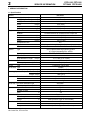
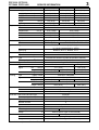
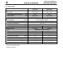
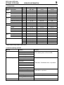
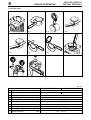
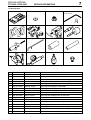
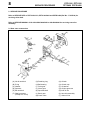
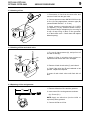
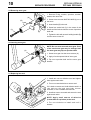
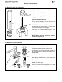
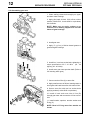
17-21C-00
PPF-2100 PPT-2100 PPT-2400 PPFD-2400
1
1
SERVICE DATA
POWER PRUNER
with new gear case
PPF-2100 PPT-2100
PPT-2400 PPFD-2400
INTRODUCTION
We are constantly working on technical
improvement of our products. For this reason,
technical data, equipment and design are subject to
change without notice. All specifications,
illustrations and directions in this SERVICE DATA
are based on the latest products information
available at the time of publication.
For further information to service these models,
please refer to ECHO SERVICE MANUAL Ord.No.
402-18.
CONTENTS
page
1 SERVICE INFORMATION .............................. 2
1-1 Specifications ............................................ 2,3
1-2 Technical data ............................................ 4
1-3 Torque limits ............................................... 5
1-4 Special repairing materials ......................... 5
1-5 Service limits .............................................. 6
1-6 Special tools ............................................... 7
2 SERVICE PROCEDURE ................................ 8
2-1 Gear case construction .............................. 8
2-2 Checking oil line ......................................... 9
2-3 Checking oil filter and check valve .............. 9
2-4 Replacing oil line and grommet .................. 9
2-5 Removing worm gear ................................. 10
2-6 Inserting worm gear ................................... 10
2-7 Replacing bar stud ..................................... 10
2-8 Replacing drive gear and bearing .............. 11
2-9 Replacing sprocket shaft gear ..................... 11
2-10Assembling gear case ................................. 12
17-21C-00
ISSUED: 200007
Reference No.
INDEX
2
PPF-2100 PPT-2100
PPT-2400 PPFD-2400
SERVICE INFORMATION
1 SERVICE INFORMATION
1-1 Specifications
Models
PPF-2100
Dimensions Length(collapsed)
Length(fully extended)
mm(in)
mm(in)
2365 (93.1)
N/A
Length(with extension)*
mm(in)
3288 (129.5)
Width
Height
mm(in)
mm(in)
230 (9.06)
221 (8.70)
kg(lb)
5.82 (12.8)
Dry weight**
Engine
Type
Rotation
cm3(in3)
mm(in)
mm(in)
Displacement
Bore
Stroke
Compression ratio
Diaphragm, horizontal-draught, with primer (purge pump)
ZAMA C1U-K52
CDI (Capacitor discharge ignition) system
in a single integrated piece w/ESG
BPMR7A, RCJ-7Y, BPM7A, CJ-7Y
Automatic rewind
Spark plug
Type
Rope diameter x length
Fuel
Clutch
Type
Tank capacity
Type
Drive shaft Type
Diameter - Length
Housing(Operation Rod)
mm(in)
cm3(U.S.fl.oz.)
mm(in)
OD - ID mm(in)
Length mm(in)
Gear case Reduction ratio
Gear tooth
Lubrication
Guide bar / Saw chain lubrication type
Tank capacity, oil cm3(U.S.fl.oz.)
Sprocket
Type
Number of teeth
Pitch
in
Guide bar Type
Called length
cm(in)
Gauge
in
Saw chain Number of drive links
pitch
in
Gauge
in
* Extension is an option.
OD: Outer Dia., ID: Inner Dia.
32.2 (1.268)
26.0 (1.024)
6.5
Carburetor Type
Model
Ignition
Type
Starter
KIORITZ, air-cooled, two-stroke, single cylinder
Counterclockwise as viewed from the output end
21.2 (1.294)
3.0 x 1000 (0.12 x 39.4)
Premixed two-stroke fuel (Refer to Operator's manual.)
420 (14.2)
Centrifugal, 2-shoe slide
Flexible
6.1 - 1854 (0.24 - 73.0)
25.4 - 23.6 (1.00 - 0.93)
1829 (72.0)
1.5
Spiral bevel, Spur
Lithium based grease
Automatic
225 (7.6)
Spur
6
3/8
Sprocket nose
25.4 (10)
0.043 (0.050 for Type 1E and Canada)
39
3/8
0.043 (0.050 for Type 1E and Canada)
PPF-2100 PPT-2100
PPT-2400 PPFD-2400
Models
PPT-2100
PPT-2400
PPFD-2400
mm(in)
mm(in)
2260 (89.0)
3410 (134.3)
2734 (107.6)
3884 (152.9)
2320 (91.3)
N/A
Length(with extension)*
mm(in)
5000 (196.9)
5468 (215.3)
3910 (153.9)
Width
mm(in)
230 (9.06)
230 (9.06)
220 (8.66)
Height
Dry weight
mm(in)
kg(lb)
221 (8.70)
7.27 (16.0)
221 (8.70)
7.85 (17.3)
230 (9.06)
6.95 (15.3)
Dimensions Length(collapsed)
Length(fully extended)
Engine
Type
KIORITZ, air-cooled, two-stroke, single cylinder
Rotation
Displacement
Bore
Stroke
cm3(in3)
mm(in)
mm(in)
Compression ratio
Starter
Clutch
Drive shaft Type
Upper
Housing
Lower
Type
Upper
34.0 (1.339)
26.0 (1.024)
6.3
ZAMA C1U-K52
WALBRO WT424B
CDI (Capacitor discharge ignition) system
in a single integrated piece w/ESG
BPMR7A, RCJ-7Y, BPM7A, CJ-7Y
Automatic rewind
Spark plug
Type
Type
Tank capacity
Type
32.2 (1.268)
26.0 (1.024)
Diaphragm, horizontal-draught, with primer (purge pump)
Model
Type
Rope diameter x length
Fuel
Counterclockwise as viewed from the output end
21.2 (1.294)
23.6 (1.440)
6.5
Carburetor Type
Ignition
3
SERVICE INFORMATION
mm(in)
cm3(U.S.fl.oz.)
OD
mm(in)
Length mm(in)
Length mm(in)
Upper / Lower
OD - ID
Length
OD - ID
Length
mm(in)
mm(in)
mm(in)
mm(in)
3.0 x 1000 (0.12 x 39.4)
Premixed two-stroke fuel (Refer to Operator's manual.)
420 (14.2)
Centrifugal, 2-shoe slide
Aluminum extrusion
15.1 (0.59)
1588 (62.5)
2026 (79.8)
1543 (60.75)
Aluminum / Fiberglass
Fiberglass
15.8 (0.62)
1760 (69.3)
N/A
34.6 - 32.1 (1.36 - 1.26)
1594 (62.8)
2032 (80.0)
356 (14.0)
Lower
46.5 - 38.9 (1.83 - 1.53)
1524 (60.0)
1491 (58.7)
Gear case Reduction ratio
1.5
Gear tooth
Spiral bevel, Spur
Lubrication
Lithium based grease
Guide bar / Saw chain lubrication type
Automatic
3
225 (7.6)
Tank capacity, oil cm (U.S.fl.oz.)
Sprocket
Type
Spur
Number of teeth
6
Pitch
in
3/8
Guide bar Type
Sprocket nose
Called length
in
10
12
Gauge
in
0.043 (0.050 for Type 1E and Canada)
Saw chain Number of drive links
39
44
pitch
in
3/8
Gauge
in
0.043 (0.050 for Type 1E and Canada)
*Extension is an option.
OD: Outer Dia., ID: Inner Dia.
4
PPF-2100 PPT-2100
PPT-2400 PPFD-2400
SERVICE INFORMATION
1-2 Technical data
Models
Engine
Idling speed
rpm
Engine speed at maximum power
Clutch-in speed
Compression pressure
Ignition system
Spark plug gap
rpm
rpm
2)
MPa(kgf/cm (psi)
mm(in)
PPF-2100
PPT-2100
PPT-2400
PPFD-2400
2500 - 3000
2500 - 3000
7500
3700 - 4100
0.85 (8.5) (121)
7500
3700 - 4100
0.75 (7.5) (107)
0.6 - 0.7 (0.024 - 0.028)
Minimum secondary voltage at 1000 rpm kV
Secondary coil resistance
Pole shoe air gaps
Ignition timing
Carburetor Model
Type
Supplier
Venturi Size
Throttle Bore
Idle speed screw initial setting
kΩ
mm(in)
1.3 - 1.8
0.3 - 0.4 (0.012 - 0.016)
°BTDC
( 33 ) 28
28
C1U-K52
WT424B
Diaphragm horizontal-draught
ZAMA
Walbro
H needle initial setting
mm(in)
mm(in)
turn in
turn back
L needle initial setting
Test Pressure, minimum
turn back
MPa(kgf/cm2)(psi)
Metering lever height
BTDC: Before top dead center.
H needle: High speed needle.
L needle: Idle needle.
15
mm(in)
18.5 (0.335)
12.7 ( 1/2 )
3-4
1 3/4
7.94 (0.313)
12.7 ( 1/2 )
3-4
3 1/4
1 3/4
0.05 (0.5) (7.0)
0.1 - 0.25
2 1/4
0.05 (0.5) (7.0)
1.65
PPF-2100 PPT-2100
PPT-2400 PPFD-2400
5
SERVICE INFORMATION
1-3 Torque limits
Descriptions
Size
kgf•cm
N•m
in•lbf
Starter
system
M 8
M 4*
80 - 100
22 - 28
8 - 10
2.2 - 2.8
70 - 90
19 - 24
M 4*
38 - 55
3.8 - 5.5
33 - 48
M 4*
38 - 55
3.8 - 5.5
33 - 48
Spark plug
Carburetor insulator
M14
M 5*
150 - 170
30 - 40
15 - 17
3-4
130 - 150
25 - 35
Carburetor
M 5
35 - 45
3.5 - 4.5
30 - 40
Throttle wire housing nut
Fuel tank
M 6
M 5*
6 - 10
27 - 32
0.6 - 1.0
2.7 - 3.2
5-9
23 - 28
Pawl carrier
Starter case
Ignition Ignition coil
system Fan cover
Fuel
system
Clutch
Clutch hub
M 8
180 - 200
18 - 20
160 - 175
Engine
Crankcase
Cylinder
M 5
M 5
75 - 85
75 - 85
7.5 - 8.5
7.5 - 8.5
65 - 75
65 - 75
Cylinder cover
M 4*
35 - 45
3.5 - 4.5
30 - 40
Muffler
Top guard
Housing
M 5
M 5*
M 4*
55 - 65
25 - 35
25 - 40
5.5 - 6.5
2.5 - 3.5
2.5 - 4.0
50 - 55
22 - 30
29 - 46
Oil tank
Auto-oiler
Regular bolt, nut, and screw
M 4*
M 4*
M 3
25 - 40
25 - 40
6 - 10
2.5 - 4.0
2.5 - 4.0
0.6 - 1.0
29 - 46
29 - 46
5-9
M 4
M 5
15 - 25
25 - 45
1.5 - 2.5
2.5 - 4.5
13 - 22
22 - 40
45 - 75
4.5 - 7.5
40 - 65
Gear
case
M 6
* Apply thread locking sealant. (See below.)
1-4 Special repairing materials
Material
Grease
Thread locking sealant
Adhesive
Liquid seal
Location
Drive shaft
Remarks
Gear case
Rewind spring
Starter center post
Starter case
Ignition coil
Fan cover
Carburetor insulators
Fuel tank
Lithium based grease or ECHO LUBETM
Cylinder cover
Top guard
Gear case housing
Oil tank
Auto-oiler
Oil pipe grommet
Bar stud
Bearing (PPFD-2400 shaft)
Gear case
Loctite #222, ThreeBond #1342, or equivalent
Loctite #242 or equivalent
Loctite #424 or equivalent
Loctite #609 or equivalent
Loctite #593, DOW #732 or equivalent
6
SERVICE INFORMATION
PPF-2100 PPT-2100
PPT-2400 PPFD-2400
1-5 Service limits
A
5K193
B
C
D
5K228
5K229
5K230
E
F
G
H
5K231
5K016
5K042
5K194
K
L
1
2
3
4
5
6
5K171
5K071
7
0
8
5
10
9
10
11
Description
A Cylinder bore
B Piston outer diameter
C Piston pin bore
D Piston ring groove
E Piston ring side clearance
F Piston pin outer diameter
G Piston ring width
H Piston ring end gap
K Crankshaft runout
L
Clutch drum bore
Min.
Max.
Max.
Max.
Min.
Min.
Max.
Max.
Max.
mm (in)
PPF-2100 PPT-2100
PPT-2400 PPFD-2400
When plating is worn and aluminum can be seen
32.10 (1.264)
33.90 (1.335)
8.030 (0.3161)
1.6 (0.063)
0.1 (0.004)
7.98 (0.3142)
1.45 (0.057)
0.5 (0.02)
0.05 (0.002)
51.5 (2.03)
PPF-2100 PPT-2100
PPT-2400 PPFD-2400
7
SERVICE INFORMATION
1-6 Special tools
1
2
3
4 : a = 4 mm
5 : a = 3 mm
a
6
7
8
9
10
11
12
13
14
15
16
17
Key
1
Part Number
Description
Tachometer
Used for:
Measuring engine speed
2
3
4
5
6
363018-00310
433019-12330
895610-79920
895612-79920
897701-06030
Washer
Flange nut
L-hex wrench (4 mm)
L-hex wrench (3 mm)
Bearing wedge
Installing crankcase oil seal of starter side
Removing magneto rotor (flywheel) Use key No.18 together
Removing and installing hex. socket bolts (M5)
Removing and installing hex. socket bolts (M4)
Removing ball bearings on crankshaft
7
8
9
10
11
12
13
14
15
16
17
897701-14732
897702-30131
897705-11520
897708-19835
897712-04630
897714-24330
897726-09130
897800-79931
897803-30130
897835-16131
900100-08008
Bearing tool
Piston pin tool
Bearing tool
Worm remover
2-pin wrench
Oil seal tool
Oil seal tool
Spark tester
Pressure tester
Pressure connector
Bolt
Removing and installing crankcase ball bearings
Removing and installing piston pin (Use 8 mm dia. adapter.)
Removing and installing con-rod small end needle bearing
Removing and installing worm for auto-oiler
Removing and installing pawl carrier
Installing crankcase oil seals
Removing clutch drum and installing drive gear ball bearing
Checking ignition system
Checking carburetor and crankcase leakages
Checking crankcase and cylinder leakages
Removing magneto rotor (flywheel) Use key No.3 together
8
PPF-2100 PPT-2100
PPT-2400 PPFD-2400
SERVICE PROCEDURE
2. SERVICE PROCEDURE
Refer to SERVICE DATA of PPF-2100/2110, PPT-2100/2400 and PPFD-2400 (Ref. No. 17-21B-00) for
servicing drive shaft.
Refer to SERVICE MANUAL of CS-3000/3050/3400/3450 or CS-4200/4400 for servicing auto-oiler
assembly.
2-1 Gear case construction
(A)
(T)
(B)
(E)
(S)
(R)
(Q)
(C)
(D)
(C)
(P)
(J)
(G)
(H)
(O)
(N)
(K)
(M)
(I)
(H)
(G)
(F)
(L)
(H)
(A)
(B)
(C)
(D)
(E)
(F)
Nut for stud bolt
E-ring
Washer
Sprocket
Bar stud bolt
Shaft connector
(Except PPF-2100)
(G) Retaining ring
(H) Ball bearing
(I) Drive gear
(J) Worm gear
(K) Sprocket shaft
(L) Bevel gear
(M) Check valve
(N) Oil tank
(O) Oil tank cap
(P) Oil strainer
(Q) Oil pipe grommet
(R) Inlet oil line
(S) Auto-oiler assembly
(T) Outlet oil line
PPF-2100 PPT-2100
PPT-2400 PPFD-2400
SERVICE PROCEDURE
9
2-2 Checking oil line
1. Disconnect oil line from the auto-oiler and
remove oil tank from the gear case.
2. Connect pressure tester #897803-30130 to the
oil line (A) using appropriate connector pipe (B)
(recommended outer dia. : 4 - 5 mm).
3. Apply pressure approximately 0.01 MPa
(0.1 kgf/cm2) (1.5 psi). Pressure should not drop.
If the pressure drops, leakage may be occurring at
oil cap, oil cap O-ring, oil tank, oil line, grommet,
or oil tank check valve. Check them and replace
defective part(s).
(B)
(A)
2-3 Checking oil filter and check valve
1. Pry out oil pipe grommet (A), and pull out oil
line and oil filter (B).
(C)
(A)
(D)
2. Wash oil filter in suitable clean solvent or
replace the filter with a new one if damaged.
(B)
3. Remove oil tank check valve (C), and clean it.
4. Check if the valve lips (D) are hardened or left
opened. Replace as required.
5. Insert oil tank check valve until flush with oil
tank.
2-4 Replacing oil line and grommet
(A)
1. Remove defective oil line and the grommet.
2. Insert new oil line to the grommet as shown.
(A): 50 mm (2 in)
NOTE: Apply an adhesive (Loctite #424 or
equivalent) at the grommet.
3. Connect oil filter to oil line.
10
SERVICE PROCEDURE
PPF-2100 PPT-2100
PPT-2400 PPFD-2400
2-5 Removing worm gear
(A)
1. Remove E-ring, washer, sprocket, another
washer, then auto-oiler.
2. Screw worm remover #897708-19835 (A) on to
the worm.
(B)
3. Insert handle (B) in the tool.
4. Screw hex socket bolt (C) in the center of the
handle until the bolt touches the center of sprocket
shaft end.
(C)
5. Tighten the bolt with wrench holding handle (B)
until the worm comes off.
2-6 Inserting worm gear
(A)
NOTE: Do not reuse removed worm gear. Bore
of the used worm gear may be enlarged and
the worm gear may slip on sprocket shaft.
1. Screw worm gear into the worm remover (A).
2. Apply oil to the tapered side of worm gear.
3. Tap on to sprocket shaft until the worm gear
bottoms.
2-7 Replacing bar stud
1. Install two nuts on defective stud and tighten
them against each other.
2. Turn nut counterclockwise to remove stud.
oc
60 tite
9
If it is hard to remove stud, hold defective stud in a
vise and tur n the gear case body counter
clockwise, or use a suitable stud remover.
3. Install two nuts to new stud and secure the nuts
against each other.
NOTE: Apply small amount of adhesive
(Loctite #609 or equivalent) to the stud.
4. Tur n nut clockwise to install stud until it
bottoms.
L
PPF-2100 PPT-2100
PPT-2400 PPFD-2400
SERVICE PROCEDURE
11
2-8 Replacing drive gear and bearing
1. Separate gear case and take out gear sets.
2. Remove retaining ring (A).
3. Set the bearing cage on a vise or equivalent.
4. Push out drive gear (B).
NOTE: Removed bearing may never be reused
since the cages are distorted.
5. Push in new bearing(s) using oil seal tool (C)
#897726-09130.
(C)
(A)
(B)
(D)
For PPT-2100/2400 and PPFD-2400: If shaft
connector (D) hit bottom inside of oil seal tool,
remove shaft connector and try again.
If not using oil seal tool, set bearing on a vise
supporting inner race and push in drive gear.
6. Install retaining ring.
NOTE: When replacing drive gear, always
replace bearings as a set.
2-9 Replacing sprocket shaft gear
1. Remove retaining ring (A) using plier.
2. Remove bearings on both sides by hand.
(B)
(C)
3. Hold bevel gear by hand as shown and tap on
the sprocket shaft to separate bevel gear from
sprocket shaft.
4. Install bevel gear (B) by hand on to sprocket
shaft aligning double D-slot (C) on the shaft and
gear.
5. Install bearing on to sprocket shaft and press
together with bevel gear.
(A)
6. Install sprocket side bearing and secure with
retaining ring.
12
SERVICE PROCEDURE
PPF-2100 PPT-2100
PPT-2400 PPFD-2400
2-10 Assembling gear case
1. Clean sealing channels thoroughly on upper
and lower case housings.
10 ic
S il a
Se
la
2. Apply thin bead of black 100% silicon rubber
sealant (DOW #732, Loctite #593 or equivalent)
into channels.
e
NOTE: Make sure to apply sealant on to
channels cut in bearing support area on both
halves of gear housings.
t
0%
on
e
nt
%
1 00 n
S i lic o
n
S e al a
3. Install gear sets.
4. Apply 17 g (6 oz) of lithium based grease to
gears and gear housings.
G r ea s e
5. Install four 3 mm hex socket bolts, tightening to
torque specification of 2.5 - 4.0 N•m (25 - 40
kgf•cm) (29 - 46 in•lbs).
6. Install worm gear onto sprocket shaft. (Refer to
2-6 Inserting worm gear.)
7. Connect outlet oil line (A) to auto-oiler.
8. Apply small amount of lithium based grease to
worm gear and install auto-oiler with outlet oil line.
(A)
9. Secure auto-oiler with two hex socket bolts
applying sealant (Loctite #242 or equivalent).
10. Install oil tank and route inlet oil line (B)
through gear case and connect the oil line to autooiler.
(B)
(C)
11. Install washer, sprocket, another washer and
E-ring (C).
NOTE: Bevel of E-ring must face washer as
shown.