1
Instructions for Use
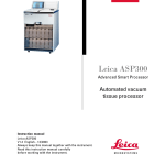
Leica ASP200 S Advanced Smart Processor
Vacuum
Tissue Processor
Leica ASP200 S, V 1.4 RevE, English – 03/2013
Order No.: 14 0480 80101, RevE
Always keep this manual with the instrument.
Read carefully before working with the instrument.
WARNING
The information, numerical data, notes and value
judgments contained in this manual represent
the current state of scientific knowledge and
state-of-the-art technology as we understand it
following thorough investigation in this field.
We are under no obligation to update the present
manual periodically and on an ongoing basis according to the latest technical developments, nor
to provide our customers with additional copies,
updates etc. of this manual.
For erroneous statements, drawings, technical
illustrations etc. contained in this manual we
exclude liability as far as permissible according to the national legal system applicable in
each individual case. In particular, no liability
whatsoever is accepted for any financial loss or
consequential damage caused by or related to
compliance with statements or other information
in this manual.
Statements, drawings, illustrations and other
information as regards contents or technical
details of the present Instructions for Use are not
to be considered as warranted characteristics of
our products.
These are determined only by the contract
provisions agreed between ourselves and our
customers.
Leica reserves the right to change technical
specifications as well as manufacturing processes without prior notice. Only in this way is it possible to continuously improve the technology and
manufacturing techniques used in our products.
This documentation is protected under copyright
laws. All copyrights to this documentation are
held by Leica Biosystems Nussloch GmbH.
Any reproduction of text and illustrations (or of
any parts thereof) by means of print, photocopy,
microfiche, web cam or other methods –
including any electronic systems and media requires express prior permission in writing by
Leica Biosystems Nussloch GmbH.
For the instrument serial number and year of
manufacture, please refer to the name plate at
the back of the instrument.
© Leica Biosystems Nussloch GmbH
Leica Biosystems Nussloch GmbH
Heidelberger Str. 17 - 19
D-69226 Nussloch
Germany
Phone: +49 6224 143-0
Fax:
+49 6224 143-268
Internet:http://www.LeicaBiosystems.com
Leica ASP200 S
3
Contents
1.
Important Information................................................................................................................ 6
1.1
1.2
1.3
1.4
Symbols in the text and their meanings..................................................................................... 6
Qualification of personnel............................................................................................................ 8
Intended use of instrument.......................................................................................................... 8
Instrument type.............................................................................................................................. 8
2.Safety............................................................................................................................................ 9
2.1 Safety notes.................................................................................................................................... 9
2.2Warnings......................................................................................................................................... 9
2.3 Safety features on the instrument............................................................................................ 13
3.
Instrument Components and Specifications........................................................................ 14
4.
Initial Operation........................................................................................................................ 24
3.1
3.2
3.3
3.4
3.5
3.6
3.6.1
4.1
4.1.1
4.2
4.2.1
4.2.2
4.3
4.4
4.5
4.6
4.7
4.8
4.9
4.10
Overview - instrument components......................................................................................... 14
Specific instrument options....................................................................................................... 16
Standard delivery - packing list................................................................................................ 17
Technical Data............................................................................................................................. 19
Compatible reagents................................................................................................................... 21
Recommended reagent handling.............................................................................................. 22
Cycle for changing reagents..................................................................................................... 23
Installation site requirements.................................................................................................... 24
Moving the instrument................................................................................................................ 24
Electrical connection.................................................................................................................. 25
Connecting the power supply.................................................................................................... 25
Connecting an uninterruptible power supply (UPS).............................................................. 26
Installing accessories................................................................................................................. 27
Making the data connections.................................................................................................... 29
Anti-reflection clip – Function................................................................................................... 30
Alarm functions............................................................................................................................ 31
Switching the instrument on...................................................................................................... 32
Touchscreen functions............................................................................................................... 34
Checklist for initial operation..................................................................................................... 35
Switching off the instrument..................................................................................................... 36
5.Operation.................................................................................................................................... 37
5.1
5.1.1
5.1.2
5.1.3 4
Setting up the instrument parameters..................................................................................... 37
System setup................................................................................................................................ 37
Access levels............................................................................................................................... 40
INSTALLATION menu................................................................................................................. 42
Instructions for Use V 1.4, RevE – 03/2013
Contents
5.1.4 Editing the reagent list................................................................................................................ 45
5.1.5 Viewing the program list............................................................................................................ 48
5.1.6 Adding and/or modifying programs.......................................................................................... 49
5.1.7Favorites........................................................................................................................................ 52
5.1.8 Configuring the stations............................................................................................................. 54
5.1.9 Reagent groups............................................................................................................................ 55
5.2 Reagent handling......................................................................................................................... 56
5.2.1 Draining/filling reagents (other than paraffin)........................................................................ 56
5.2.2 Replacing the paraffin................................................................................................................ 58
5.3 Running programs....................................................................................................................... 61
5.3.1 Editing a program that has been called up. ........................................................................... 62
5.3.2 Starting a program...................................................................................................................... 64
5.3.3 Opening the retort during a program interruption................................................................. 65
5.3.4 Retort emergency release......................................................................................................... 65
5.4 Reagent status............................................................................................................................. 67
5.5 System monitor............................................................................................................................ 68
5.6 The online help............................................................................................................................. 69
6.Troubleshooting........................................................................................................................ 70
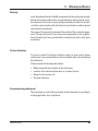
6.1General.......................................................................................................................................... 70
6.2 Power failure................................................................................................................................ 70
6.3Troubleshooting........................................................................................................................... 71
6.4 Typical fill or drain problems..................................................................................................... 72
7.
Cleaning and Maintenance..................................................................................................... 73
7.1
7.1.1
7.1.2
7.1.3
7.2
7.2.1
7.2.2
7.3
Clean programs............................................................................................................................ 73
Retort cleaning programs.......................................................................................................... 73
Paraffin cleaning......................................................................................................................... 75
Smart clean................................................................................................................................... 76
General cleaning steps............................................................................................................... 77
Daily cleaning and maintenance.............................................................................................. 79
Periodic cleaning and maintenance........................................................................................ 81
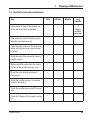
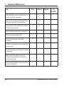
Checklist for preventive maintenance..................................................................................... 83
8. Warranty and Service.............................................................................................................. 85
Appendix 1............................................................................................................................................ 86
Notes on Specimen Preparation.......................................................................................................... 86
Leica ASP200 S
5
1. Important Information
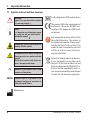
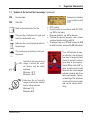
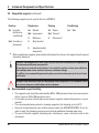
1.1 Symbols in the text and their meanings
Warnings
appear in a gray box and are marked
by a warning triangle .
Notes,
i.e. important user information appear
in a gray box and are marked by an –
information symbol
.
Inflammable solvents and reagents are
marked with this symbol.
Instrument surfaces which become hot
during operation are marked with this
symbol.
Avoid direct contact with these surfaces - they may cause burns.
(5)
Numbers in parentheses refer to item
numbers in illustrations.
ENTER
Function keys to be pressed on the
instrument touchscreen are written in
bold-print capital letters.
In vitro diagnostics (IVD) medical device
This product fulfills the requirements of
the Council's Directive 98/79/EC concerning in vitro diagnostics (IVD) medical devices.
Environmental protection symbol of the
China RoHS directive. The number in
the symbol indicates the "Environmentfriendly Use Period" of the product. The
symbol is used if a substance restricted
in China is used in excess of the maximum permitted limit.
Symbol for labeling electrical and electronic equipment in accordance with
Section 7 of the German Electrical and
Electronic Equipment Act (ElektroG). ElektroG is the law regarding the sale, return and environmentally sound disposal
of electrical and electronic equipment.
Manufacturer
6
Instructions for Use V 1.4, RevE – 03/2013
1. Important Information
1.1 Symbols in the text and their meanings (continued)
SN
Serial number
REF
Order No.
Observe the Instructions for Use
The package contents are fragile and
must be handled with care.
Indicates the correct upright position of
the package.
The package must be kept in a dry environment.
Indicates the temperature
range to which the medical device can be safely
exposed.
Minimum –29 °C
Maximum +50 °C
Indicates the air humidity
range to which the medical
can be safely exposed.
Minimum 10 %
Maximum 85 %
Leica ASP200 S
Example of labeling
in accordance with
IPPC.
• IPPC symbol
• Country code in accordance with ISO 3166,
e.g. DE for Germany
• Regional identifier, e.g. HE for Hessen
• Producer/treatment provider code, unique
assigned number starting with 49
• Treatment code, e.g. HT (heat treatment), MB
(methyl bromide), and possibly DB (debarked).
Tip-n-Tell indicator to monitor whether the shipment
has been transported and
stored in upright position
according to your requirements. With a pitch of 60 ° or
more, the blue quartz sand
flows into the arrow-shaped
indicator window and sticks
there permanently. Improper handling of the shipment
is immediately detectable
and can be proven definitively.
7
1. Important Information
1.2 Qualification of personnel
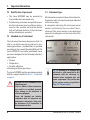
1.4 Instrument type
• The Leica ASP200 S may be operated by
trained laboratory personnel only.
• All laboratory personnel designated to operate this instrument must read these Instructions for Use carefully and must be familiar
with all technical features of the instrument
before attempting to operate it.
All information provided in these Instructions for
Use applies only to the instrument type indicated
on the cover page.
A nameplate indicating the instrument serial
number is attached to the rear side of the instrument. (The serial number is also displayed
above the loading door on the front side of the
instrument.)
1.3 Intended use of instrument
The instrument has been designed so that it is
safe to use by the operator as well as for processing specimens – provided that it is operated
according to the present Operating Manual. The
Leica ASP200 S is a modular automated tissue
processor designed for the following laboratory
applications:
• Fixation
• Dehydration
• Paraffin infiltration
of histological tissue specimens.
The Leica ASP200 S must be operated exclusively
with the reagents listed in Chap. 3.5 - "Compatible
reagents".
Any other use of the instrument is considered improper.
Failure to adhere to these instructions
may result in an accident, personal
injury, damage to the instrument or
accessory equipment.
Proper and intended use includes
compliance with all inspection and
maintenance instructions, along with
the observance of all instructions in
the Instructions for Use.
8
Fig. 1
Fig. 1 is provided as an example only
and shows a valid nameplate for this
instrument with the necessary information about instrument type and
power requirement. The precise data
for the various versions is specified in
Chap. 3.2 "Technical data".
Instructions for Use V 1.4, RevE – 03/2013
2. Safety
2.1 Safety notes
• The safety and caution notes in this chapter must be observed at all times.
• Be sure to read these notes even if you are already familiar with the operation and use of
other Leica products.
• The protective devices located on the instrument and the accessories must not be removed
or modified. Only qualified service personnel authorized by Leica may repair the instrument
and access its internal components.
Residual risks
• The instrument has been designed and constructed with the latest state-of-the-art technology and according to recognized standards and regulations with regard to safety technology.
Operating or handling the instrument incorrectly can place the user or other personnel at
risk of injury or can cause damage to the instrument or other property. The instrument may
be used only as intended and only if all of its safety features are in proper working condition.
Malfunctions which could impede safety must be remedied immediately.
• Only original spare parts and permitted original accessories may be used.
These Instructions for Use includes important
information related to the operating safety and
maintenance of the instrument.
The Instructions for Use are an important part of
the product, and must be read carefully prior to
startup and use and must always be kept near
the instrument.
These Instructions for Use must be appropriately supplemented as required
by the existing regulations on accident
prevention and environmental safety in
the operator‘s country.
This instrument has been built and tested in
accordance with the safety requirements for
electrical equipment for measurement, control,
and laboratory use.
To maintain this condition and ensure safe
operation, the user must observe all notes and
warnings contained in these Instructions for Use.
For current information about applicable standards, please refer to the
CE declaration for the instrument and
to our Internet site:
http://www.LeicaBiosystems.com
2.2Warnings
The safety devices installed in this instrument by the manufacturer only constitute the basis for
accident prevention. Operating the instrument safely is, above all, the responsibility of the owner,
as well as the designated personnel who operate, service or repair the instrument.
To ensure trouble-free operation of the instrument, be sure to comply with the following instructions and warnings.
Leica ASP200 S
9
2.Safety
2.2Warnings (continued)
Warnings – Markings on the instrument itself
Markings on the instrument showing the warning triangle indicate that the correct operating
instructions (as defined in these Instructions for Use) must be followed when operating or replacing the item marked. Failure to adhere to these instructions may result in an accident, personal injury, damage to the instrument or accessory equipment.
Some instrument surfaces become hot during operation. They are marked with this
warning label. Touching these surfaces may cause burns.
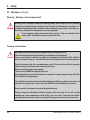
Transport and Installation
Once unpacked, the instrument may be transported only in an upright position.
Follow the unpacking instructions carefully to avoid damage to the instrument!
Prior to every transport in which it is possible for the instrument to be shaken, tilted, or lifted, it
must be cleaned for transport – otherwise the interior of the instrument can be severely damaged.
Plug the instrument only into a grounded power socket. Do not interfere with the grounding
function by using an extension cord without a ground wire.
Make sure to observe the voltage settings!
The set voltage CANNOT be changed by the user.
Severe damage may occur if the instrument is connected to a power supply voltage other than
that to which it was originally set.
The installation location must be well-ventilated; there should be no ignition sources there of
any kind. The chemicals to be used in the Leica ASP200 S are both flammable and noxious.
Do not operate the instrument in rooms with explosion hazard.
Extreme temperature fluctuations between storage facility and setup site as well as high
humidity may cause condensation to form. If this is the case, wait at least two hours before
switching on the instrument. Failure to comply with this may cause damage to the instrument.
10
Instructions for Use V 1.4, RevE – 03/2013
2. Safety
2.2Warnings (continued)
Warnings – Operating the instrument
The instrument may only be operated by trained laboratory personnel. It must only be operated for the purpose of its designated use and according to the instructions contained in these
Instructions for Use.
In an emergency, the instrument can be switched off while working with specimens via the
ON/STOP switch located on the side of the instrument.
Before opening the retort when an infiltration process is in progress, always press the PAUSE
button so that the retort is ventilated or vented.
The paraffin drain hose and the hose for remote filling/draining are cleaned with compressed
air after the filling or draining process.
Therefore, never remove the hoses before a filling or draining process has been completed.
After refilling/replacing reagent containers, close the container covers again tightly.
The reagent containers must be properly pushed home into the connection manifolds at the
rear inner wall of the reagent module.
Failure to plug the reagent containers into the manifold correctly will interrupt the infiltration
process and may also result in spilling of reagents.
Fixing solutions that contain mercury salts, acetic acid, or picric acid can cause corrosion on
metal components.
After each paraffin step a retort clean cycle must be run.
Material safety data sheets can be obtained from the supplier of the chemicals.
Alternatively, they can be downloaded from the following website:
http://www.msdsonline.com
Leica ASP200 S
11
2.Safety
2.2Warnings (continued)
Warnings – Handling reagents
Take care when handling solvents!
Always wear rubber gloves and safety goggles when handling the chemicals used in this
instrument.
Reagents used for tissue infiltration can be both toxic and/or flammable.
To prevent damage to the instrument, use only the reagents listed in Chap. 3.5!
Do not use acetone, benzene or trichlorethane!
Use caution when handling paraffin wax or removing baskets – molten paraffin is hot and may
cause burns.
Also, avoid personal contact with paraffin reservoirs and retort walls – they can be very hot as
well.
When disposing of spent reagents, observe the applicable local regulations and the waste
disposal regulations of the company/institution in which the instrument is being operated.
Do not clean reagent containers (bottles) in a dishwasher; the containers are NOT dishwasherproof.
Warnings – Cleaning and maintenance
Switch off the instrument each time before servicing and pull out the power plug.
Do not clean the instrument with solvents containing acetone or xylene. No liquid may be
spilled into the internal components of the instrument – neither during operation nor during
cleaning.
When using cleaners, please comply with the safety instructions of the manufacturer and the
laboratory safety regulations.
Check the condensate container at least once a week and, if necessary, drain it.
12
Instructions for Use V 1.4, RevE – 03/2013
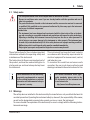
2. Safety
2.3 Safety features on the instrument
Overpressure protection
Overcurrent protection
Overheating protection
Over vacuum protection
Overcurrent protection
Leica ASP200 S
The Leica ASP200 tissue processor is equipped with numerous safety functions and with sophisticated software control mechanisms. These ensure
that the specimens remain undamaged in the event of a power failure or
other malfunction during the infiltration process and that the infiltration is
completed successfully.
• When power is off the air pump and air valves default to a safe condition
(retort vented, no pressure generation).
• If the pump is not stopped at the correct moment during the pressurization, the power supply is interrupted by a separate electronic circuit.
• In addition, there is a safety relief valve that vents all excess air pump
output to atmosphere.
• Overcurrent conditions are protected against by both the main fuse and
the separate heating power fuses.
An error is indicated and all heating is stopped by the microprocessor –
control if the instrument detects any of the following conditions:
• Abnormally high temperature (>75 °C)
• Contradictory results of the temperature sensors
• Failure of one or more heating power control components
• If the microprocessor fails to interrupt heating power, independent temperature limiting hardware circuits limit the temperature rise to a safe
level.
• If the temperature limiting circuits malfunction, an independent hardware thermal fuse circuit cuts power to the heating elements.
• The vacuum system is not capable of generating a dangerous vacuum
condition.
• Overcurrent conditions are protected against by both the main fuse and
the separate heating power fuses.
13
3. Instrument Components and Specifications
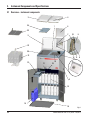
3.1 Overview – instrument components
4
3
1
24
6
22
7
5
10
9
23
20
21
13
12 11
8
19
17
18
2
15
14
16
14
Fig. 2
Instructions for Use V 1.4, RevE – 03/2013
3. Instrument Components and Specifications
Overview – instrument components
Instrument Components and Accessories
1 - Basic instrument – processor module
2 - Basic instrument – reagent module
3 - Wax bath lids
4 - Retort lid
5- Monitor
6 - Cover flap of the instrument console
7 - Instrument console with:
8 - Printer port
9 - Local alarm connection
10 - Remote alarm connection
11 - Disk drive
12 - Serial port
13 - Active carbon filter
14 - Condensate container
15 - Reagent containers (13 units)
16 - Drip tray
17 - Paraffin drain spout
18 - Remote drain connection
19- Retort
20 - Wax baths
21 - Cassette basket
22 - Lid for cassette basket
23 - Basket carrier
24 - Baffle plate
25 - Volume replacement body
Three wax baths and the retort comprise the
infiltration module.
The touchscreen and the electronic components
are there.
The cassettes are stored in two baskets (Fig. 2, 21)
each of which holds up to 84 cassettes with
dividing spiral or up to 100 cassettes without
dividing spiral.
The specimens are processed in the stainless
steel retort at the preselected pressure, vacuum,
and temperature conditions.
The reagent containers are located in the
reagent cabinet.
Leica ASP200 S
15
3. Instrument Components and Specifications
3.2 Specific instrument options
• Optionally usable Reagent Management System (RMS), displays service life and usage frequency of the individual reagents and enables automatic definition of the reagent sequence
– there is no more need to rearrange reagent containers. If one or more reagents within a
sequence are replaced, the RMS automatically uses the reagents in the correct sequence,
organized in ascending order of cleanliness.
• Liquid movement ("wave motion") during the process for better and continuous mixture of
the reagents.
• System for non-contact filling/draining of reagents – drains and fills the reagent container
using a hose connected to the infiltration module without the operator being exposed to
reagents in the process.
• Non-contact wax bath drainage.
• Optical level meter.
• Active paraffin cleaning program – removes solvent residue from the paraffin, lengthening
its service life.
• Magnetic stirrer – for gentle circulation of the reagents, thus ensuring a uniform reagent
temperature.
• Programmable end time for infiltration programs.
• 3-step drainage of the retort (adjustable) for reducing reagent displacement.
• Infiltration process at ambient pressure, or with pressure, vacuum or a combination of both.
• Four programmable cleaning programs. The cleaning programs automatically omit all steps
that are not necessary to complete the cleaning procedure.
16
Instructions for Use V 1.4, RevE – 03/2013
3. Instrument Components and Specifications
3.3 Standard delivery - packing list
To prevent damage to the instrument or specimens, only accessories and spare parts authorized by Leica may be used.
The standard equipment of the Leica ASP200 S includes the following parts:
1
Leica ASP200 S basic instrument
13 Reagent bottles, plastic (in the instrument)
1 Condensate container, plastic (in the instrument)
1 Collecting vessel (in the instrument)
1 3.5 " diskette, empty (affixed to the rear side of the console cover)
1 Accessory kit, consisting of:
1 Basket set ASP200 S, consisting of:
1 Basket handle ASP200 S
1 Basket carrier ASP200 S
2 Plastic baskets with integrated spacers
1 Stainless steel basket cover for the top basket
1 Stirrer
1 Volume replacement body
1 Reagent bottle, plastic
2 Set of adhesive bottle labels, 24 pcs. each
1 Funnel
2 Active carbon filter assembly
1 Filling/draining hose assembly
1 Paraffin drain hose
1 Paraffin scraper, plastic
1 Lubricant for valves and O-rings (Molykote 111, 100 gr)
1 Connecting cable - power supply
1 Maintenance kit (2 spare covers, 9 O-rings)
1 Baffle plate
1 Single-head wrench, size 27
1 Allen key, size 3.0
Leica ASP200 S
Part No.
14 0480 37121
14 0480 37122
14 0476 37350
14 0476 35915
14 0480 43728
14 0480 43577
14 0476 34713
14 0480 43578
14 0476 43569
14 0476 43362
14 0476 43630
14 0480 37127
14 0480 37121
14 0200 43464
14 0476 43631
14 0476 34150
14 0476 34716
14 0476 34721
14 0476 35923
14 0336 35460
14 0411 34604
14 0476 35921
14 0476 34770
14 0330 50891
14 0222 04138
17
3. Instrument Components and Specifications
3.3 Standard delivery – packing list (continued)
1
1
1
1
1
1
1 Remote alarm connection, 6.3 mm
1 Cleaning tools for prism
1 Microfiber cloth for prism
Power cable for Germany
Power cable for UK ST-BU F-5 A
Power cable for Brazil 10 A, straight
Power cable for the USA/Canada/Japan (for voltage variant 100-120 V)
ASP200 S German/English Instructions for Use (+ language CD)
Language CD, with ASP200 S demo program
Part No.
14 6844 01005
14 0495 47955
14 0495 47736
14 0411 13558
14 0411 27822
14 0411 47869
14 0411 13559
14 0480 80001
14 0480 80200
Please check all delivered parts against the packing list and against your order to verify
whether the delivery is complete! Should you find any discrepancies, please contact your Leica sales office without delay.
18
Instructions for Use V 1.4, RevE – 03/2013
3. Instrument Components and Specifications
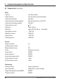
3.4 Technical Data
Nominal supply voltages:
Nominal frequency:
Main fuses:
Nominal power:
Dimensions, (L x W x H), in mm:
Empty weight, unpacked:
Weight, packed:
Operating temperature range:
Relative humidity:
IEC 1010 classification:
Altitude:
Local/remote alarm relay:
Paraffin reservoirs
Number of containers:
Capacity:
Melting time:
Temperature:
Temperature accuracy:
Leica ASP200 S
Two factory-preset voltages (not user-adjustable):
100 to 120 V
or
230 to 240 V
50 to 60 Hz
2 melting fuses, 20 x 5 mm, UL-approved
• for 100 to 120 V F 10 A 250 VAC
• for 230 to 240 V F 5 A 250 VAC
1000 VA
595 x 680 x 1325
approx. 160 kg
220 kg
15 °C to 35 °C
10 % to 80 % non-condensing
Protection class 1
Pollution degree 2
Overvoltage installation category II:
• 800 V impulse (120 V systems)
• 1500 V impulse (240 V systems)
2500 m maximum
30 V DC, maximum 2 A
2 terminals:
Each with isolated switching contact (operable both
as normally-open and normally-closed circuit)
3
4.3 l per container
approx. 10 h
40 to 65 °C
+ 1 K
19
3. Instrument Components and Specifications
3.4 Technical data (continued)
Retort
Capacity:
Reagent volume:
Temperature (paraffin):
Temperature (processing reagents):
Temperature (cleaning reagents):
Temperature accuracy:
Filling time:
Drain time:
Impregnation vacuum:
Infiltration pressure:
Filling vacuum:
Draining pressure:
max. 200 cassettes
3.5 l with volume replacement body
40 to 65 °C
Ambient temperature or 35 to 55 °C
50 to 65 °C
+ 1 K
approx. 90 sec
approx. 80, 120, 140 sec (selectable)
-70 kPa (g)
35 kPa (g)
-70 kPa (g)
35 kPa (g)
General
Reagent container:
Cleaning solution bottles:
Maximum bottle volume:
Printer:
Pretest check:
Fluid level sensor:
Recirculation (pump in/out):
(a) Time before 1st cycle:
(b) Time between cycles:
10
3
4.0 l
Optional Accessories
ON/OFF
ON/OFF
ON/OFF
16 min
20 min
System setup
Password status:
Type of password:
Reagent management system (RMS):
Software interlock:
Supervisor/Operator
alphanumeric, freely selectable
ON/OFF
ON/OFF
20
Instructions for Use V 1.4, RevE – 03/2013
3. Instrument Components and Specifications
3.4 Technical data (continued)
Hardware and Software:
• Large color LCD touchscreen.
• User-friendly, intelligent software.
• 3.5" disk drive and printer port.
• Alarm system with two remote alarm sockets.
• Password-protected instrument supervisor mode.
• Built-in multiple specimen protection system.
Capacities:
• 15 programs that consist of up to 10 reagent and 3 paraffin processing steps each.
• Time per program step: 0 to 99 h, 59 min.
• Delay time: max. 7 days
• Up to 200 cassettes can be processed simultaneously.
• 4 programmable cleaning programs for the retort.
• 1 paraffin cleaning program
• 10 reagent containers.
• 3 paraffin reservoirs.
• 3 containers for cleaning solutions
• 1 condensate container
• Reagent temperature selectable from 35 °C to 55 °C or room temperature.
• Paraffin temperature selectable from 40 °C to 65 °C.
• Choice of three retort drain rates of 80, 120 or 140 seconds.
• Up to 100 reagent names in memory.
3.5 Compatible reagents
Use of the ASP200 S is permitted with the reagents specified in Chap. 3.5 only. These reagents
must be validated before use, i.e. tissue processing with patient tissue for diagnostics, by the
laboratory itself according to the local or regional accreditation requirements. Reagents other
than those listed here may cause severe damage to the components of the instrument. Acetone,
benzene, chloroform and trichlorethane must NOT be used!
Leica ASP200 S
21
3. Instrument Components and Specifications
3.5 Compatible reagents (continued)
The following reagents may be used in the Leica ASP200 S:
Fixatives
1st
Dehydration
Formalin
(buffered or
unbuffered)
2nd Formalin replacement
1st
Ethanol
2nd Isopropanol
3.
Methanol
4.
Butyl alcohol
Clearing
1st
Paraffinizing
Xylene
1st
Wax
2nd Toluene*
3.
Chloroform*
Industrial methylated spirits
* Before using these reagents, please obtain information from Leica or the supplier about required
preventive measures.
5.
Fixatives containing mercuric salts, acetic or picric acid will corrode metallic components in
the instrument and shorten instrument life.
If you choose to work with such fixatives, it is essential to perform a clean cycle which contains multiple water rinses each time after use, to minimize damage.
In addition, we recommend frequent and regular preventive maintenance by the Leica Technical Service.
Reagents other than those listed here may damage some components of the instrument. Do not
use acetone, benzene or trichlorethane in the instrument.
3.6 Recommended reagent handling
• The reagents used should be replaced after 600 to 1200 specimens have been processed or
after 6 cycles of 100 to 200 specimens each.
• For formalin, process alcohol and process xylene reagents, ambient temperature is recommended.
• The recommended temperature for cleaning reagents in the cleaning cycle is 65 °C.
• Only zinc formalin based on zinc sulfates may be used in the ASP200 S/ASP300 S. If zinc formalin is used, the cleaning program must include an additional cleaning water step.
• The use of formalin reagents containing zinc chloride can cause corrosion in and on the
instrument.
22
Instructions for Use V 1.4, RevE – 03/2013
3. Instrument Components and Specifications
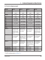
3.6.1Cycle for changing reagents
Reagent
Formalin
Formalin
70 %
80 %
95 %
95 %
100 %
100 %
Xylene
Xylene
Paraffin 1
Week 1
Week 2
Week 4
At least 3 times a
week
At least 3 times a
week
Daily
Once a week
Once a week
At least 3 times a
week
At least 3 times a
week
Daily
Once a week
---
At least 3 times a
week
At least 3 times a
week
Daily
Once a week
Once a week
At least 3 times a
week
At least 3 times a
week
Daily
Once a week
---
--Once a week
--Once a week
--Run paraffin cleaning program* daily.
Replace the paraffin after 6 cleaning
cycles.
Run the paraffin
cleaning program*
twice a week.
Once a week
--Once a week
--Once a week
Run the paraffin
cleaning program*
once a week.
--Once a week
--Once a week
--Run the paraffin
cleaning program*
twice a week.
Run the paraffin
cleaning program*
once a week.
Once a week
--Once a week
--Once a week
Run paraffin cleaning program* daily.
Replace the paraffin after 6 cleaning
cycles.
Run the paraffin
cleaning program*
twice a week.
Paraffin 3
Run the paraffin
cleaning program*
once a week.
Run paraffin cleaning program* daily.
Replace the paraffin after 6 cleaning
cycles.
Run the paraffin
cleaning program*
twice a week.
Cleaning xylene
Cleaning alcohol
Cleaning Water
Once a week
Once a week
Once a week
Once a week
Once a week
Once a week
Paraffin 2
Week 3
Run paraffin cleaning program* daily.
Replace the paraffin after 6 cleaning
cycles.
Once a week
Once a week
Once a week
Run the paraffin
cleaning program*
once a week.
Once a week
Once a week
Once a week
* Paraffin cleaning program, see Chap. 7.1.2
Leica ASP200 S
23
4. Initial Operation
4.1 Installation site requirements
• The instrument requires an installation area of
approx. 650 x 700 mm with vibration-free floor.
• Room temperature consistently between
+15 °C and +35 °C.
• Relative air humidity maximum 80 %, noncondensing.
• Avoid vibrations, direct sunlight and heavy
variations in temperature.
The chemicals to be used in the Leica
ASP200 S are both flammable and noxious. The installation site for the Leica
ASP200 S must be well ventilated, and
there must be no ignition sources of
any kind in the area. Never operate the
instrument in rooms with an explosion
hazard.
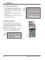
4.1.1Moving the instrument
After unpacking the instrument (see Unpacking instructions on the outside of the transport
crate), handle it only by the handles marked with
‘ ‘ to move it to its final location.
When operating the instrument, the brakes on
the instrument casters (24) must be engaged.
The instrument must be set up so that
the power switch on the rear side
of the instrument (Fig. 4, 42) is easily
accessible at any time.
24
24
Instructions for Use V 1.4, RevE – 03/2013
4. Instrument Setup
4.2 Electrical connection
Notice!
Observe the following instructions
carefully to prevent damage to the
instrument (refer also to Chap. 2.2
"Warnings – Transport and installation").
Severe damage may occur if the instrument is connected to a power supply voltage other than that to which it
was originally set.
The power supply voltage for the
instrument is factory preset and
CANNOT be altered by the user.
• Check the voltage label (Fig. 3) on the rear of
the instrument to ensure that the instrument
delivered is set to the correct voltage range.
Fig. 3
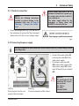
4.2.1Connecting the power supply
Once the instrument has been switched on, the main switch (ON/OFF) (5) should always remain
in the ON position.
41
• Connect the power cable (37)
to the input socket (41) of the
main power supply.
• The jumper cable provided
(38) connects the output of the
main power supply (43) to the
input of the electronics module
(40).
37
42
40
43
38
Left Fig.
Electrical ports on the rear
panel of the instrument.
Leica ASP200 S
Fig. 4
Right Fig.
Correct connection of the cables.
Important!
The specification for the
connection (40) is specified as follows:
100 - 120 V or
230 - 240 V,
maximum 200 VA.
25
4. Initial Operation
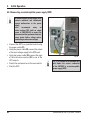
4.2.2Connecting an uninterruptible power supply (UPS)
An uninterruptible power supply (UPS)
protects machines and instruments
against malfunctions in the power
supply.
Leica
recommends
using
an
active tracking UPS (with an output
power of 1000-1500 VA) to protect the
instrument and the specimens from temporary power failure, voltage spikes,
undervoltages and excess voltages.
• Connect the ASP to a grounded socket using
the power cable (37).
• Using the jumper cable (38), connect the output
of the main voltage supply to the UPS input.
• Using the jumper cable (38) connect the input
of the electronics section (40) to one of the
UPS outputs.
• Switch the instrument on at the main switch.
• Start the UPS.
26
38a
38
37
40
Fig. 4a
Fig. 4a is provided as an example only
and shows the correct connection
of the ASP200 S to an uninterruptible
power supply (UPS).
Instructions for Use V 1.4, RevE – 03/2013
4. Instrument Setup
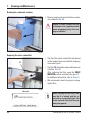
4.3 Installing accessories
13
• Move the instrument to its final setup location.
Active carbon filter
• Unpack the active carbon filter (13) and insert
it (see Fig. 5).
When doing so, make sure that the filter is
inserted with the correct side up.Note the
direction of the
label (29) on the
front of the filter the arrow must be
pointing upwards.
18
29
Fig. 5
Remote fill / drain hose
• Connect the supplied remote fill/drain hose to
the remote drain connection on the front of the
instrument (refer Fig. 6).
28
18
• Important!
When inserting the hose into the drain opening
(Fig. 5/6, 18), the connecting device (28) of the
hose must engage with a clearly audible click.
If it is possible to set up the bulk container for filling and draining in the
immediate vicinity of the instrument,
the hose can be shortened so that it is
easier to handle.
When shortening the hose, you can cut
a V-shaped notch into the hose end to
attain better flow.
Fig. 6
Leica ASP200 S
27
4. Initial Operation
4.3 Installing accessories (continued)
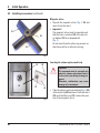
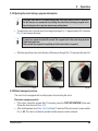
Magnetic stirrer
• Unpack the magnetic stirrer (Fig. 7, 30) and
insert it into the retort.
• Important!
The magnetic stirrer must be inserted such
that the outer curvature (32) of the two stirrer blades (31) faces downwards!
(Fig. 7)
Do not insert them the other way around, as
then there will be no effective stirring.
31
30
32
Fig. 7
19
25
Inserting the volume replacement body
26
Important!
The instrument must be operated only
when the volume replacement body is
in the retort (even during cleaning programs).
Otherwise, malfunctions may cause
damage to the instrument.
27
25
Fig. 8
28
• Take the volume replacement body (Fig. 8, 25)
at the metal clip (26) and insert it into the retort
(19) such that the bore (27) is above the position of the magnetic stirrer.
Instructions for Use V 1.4, RevE – 03/2013
4. Instrument Setup
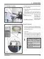
4.4 Making the data connections
Printer (optional)
• Swing the door of the instrument console (6)
upwards.
• Connect the printer to the printer port (8) using
a Centronics standard cable.
(Fig. 9)
• Your Leica dealer can recommend a suitable
printer.
• If compliance with the electromagnetic interference standards is of fundamental importance, a specially shielded printer cable must
be used.
10
9
8
11
12
6
Other terminals
• For data transfer and storage, the instrument
console has a regular 1.44 MB floppy drive
(11) for 3.5" diskettes and a serial (RS 232)
interface (12).
Fig. 9
Leica ASP200 S
29
4. Initial Operation
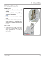
4.5 Anti-reflection clip – Function
The anti-reflection clip (Order no. 14 0476 44135) prevents any reflections that might otherwise
be emitted from the specimen basket (3, order no. 14 0476 34193) and that could affect the level
sensor in the retort, thus causing malfunctions.
Installing the clip
The anti-reflection clips are intended for
installation on the specimen basket to prevent
reflections of the level sensor.
1
4
3
2a
Fig. 10
• Insert the left lug (2a) of the anti-reflection clip (1)
into the seventh hole (from the left) of the lower oval
openings (Fig. 10).
• Snap the right lug (Fig. 11, 2b) into the seventh hole
(from the right) with gentle pressure.
When inserting or removing the metal baskets
into/from the retort, always do so carefully so
that they do not touch or become caught on
the retort wall.
Changing the clip
1
4
2b
Fig. 11
4
5
• Once the clip is installed, the handle (4) of the specimen basket cannot be removed, as otherwise the clip
will be bent.
• To remove or replace a clip, all parts that are inside
the basket (e.g. spiral insert and separating walls)
must be removed from the basket.
• Suitable tool (screwdriver 5, Fig. 12).
Once bent, clips may no longer be used and
must be disposed of. In this case, install a new
clip from the standard scope of delivery.
Fig. 12
30
Instructions for Use V 1.4, RevE – 03/2013
4. Instrument Setup
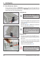
4.6 Alarm functions
The Leica ASP200 S is equipped with 3 different
alarm functions:
Instrument alarm
This instrument alarm is generated from within
the instrument itself for all alarm messages.
Local alarm
This alarm is external to the Leica ASP200 S, e.g.
in the office of the instrument operator.
The local alarm is used when the instrument
cannot continue with the current program or
operation because of a problem.
Connect the alarm system (optional)
If required, connect the local or remote alarm
system to the appropriate sockets (34) (Ø 6.3 mm)
to the jacks provided for this purpose (Fig. 9, 9 + 10).
Local alarm: socket (9)
Remote alarm: socket (10)
35
36
33
34
Leica ASP200 S
Fig. 13
Remote alarm
This alarm is also external to the Leica ASP200 S.
If installed, it might typically be connected to a
remote dialer that sends an automated phone
message to the person responsible for afterhours problems.
The remote alarm is only generated when the
instrument cannot continue with an infiltration
program.
Note that if installed, the remote alarm
will still operate even if the local
alarm is not installed.
Both, local and remote alarm options,
are relays that are voltage-isolated
from the rest of the instrument. When
an error condition occurs, the relevant
alarm circuit closes.
The remote alarm device connected
to the instrument must be rated at less
than 2 amp.
A maximum voltage of 30 V DC may be
present.
Each alarm is connected to the plug (34) as follows
(see Fig. 13):
Shared terminal:
Tip (36)
connection inside
Normally open connection:
First neck (35)
connection outside
Normally Closed Contact:
Connection:
Second neck (33)
Threaded connection
31
4. Initial Operation
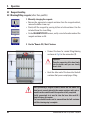
4.7 Switching the instrument on
The instrument MUST be connected to a grounded power socket.
For additional electrical fuse protection, we recommend connecting the Leica ASP200 S to a
socket with a residual current circuit breaker.
• C
onnect the power cable to the power socket. If applicable, switch on the switch for
the power socket.
• T o switch on the instrument, press in the ON/OFF switch on the rear panel of the
instrument (Fig. 4, 42) (ON).
• Switch on the ON/STOP switch on the right of the instrument (ON).
The ON/OFF switch and the side ON/STOP switch should remain switched on at all times to
keep the heater running for the wax baths.
The ON/STOP switch can be used in emergencies to stop the instrument during while a procedure is in progress.
Fig. 14
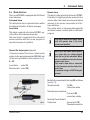
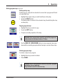
• After being switched on, the instrument will take
a few minutes to initialize. See opposite for corresponding touchscreen display (Fig. 14).
• If the retort is not locked, a signal tone sounds for
approx. 10 sec. during initialization of the instrument.
It is not possible to lock the retort during this time.
• If the retort is locked, no signal tone sounds.
A signal tone sounds for approx. 10 seconds (waiting time) when attempting to open the retort. The
retort cannot be opened during this time.
• After that, the FAVORITES screen will be displayed
(Fig. 15).
Screen saver
• A screen saver will turn off the screen display if no
key has been pressed for a (user-programmable)
time. Press any part of the touchscreen to restore
the screen.
After having been restored, the on-screen functions will be nonoperational for a few seconds to
avoid accidental activation of any keys.
Fig. 15
32
Instructions for Use V 1.4, RevE – 03/2013
4. Instrument Setup
1
2
6
3
7
4
8
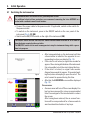
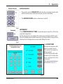
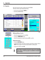
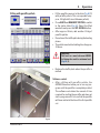
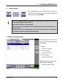
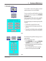
SYSTEM DIAGNOSTICS menu
If TOUCH HERE ... is touched during
initialization (Fig. 14) and the password for supervisor mode is entered, the SYSTEM DIAGNOSTICS
menu (Fig. 16) opens. This menu
provides access to basic instrument settings.
Notice!
Only experienced operators may
adjust the settings, since incorrect
use of the functions can result in
serious malfunctions.
5
Fig. 16
The following functions can be selected:
1 -Access for service technicians only.
2 -Displays the INSTALLATION menu.
3 -Aborts the current program.
4 -Aborts the current program and deletes the
current allocation of reagents to bottles and
retort.
5 - Deletes all reagents and resets programs and
instrument status (all lists will be empty).
6 -Saves the current instrument status.
7 -Displays the results log.
8 -Restarts the instrument.
To exit this menu, the device must be restarted.
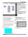
press RESTART APPLICATION.
To reinitialize the instrument, press YES to confirm the query "ARE YOU SURE YOU WANT TO ..."
(Fig. 17).
Queries such as this are always made
before important steps that are irreversible.
This allows the operator to undo
changes caused by accidental key
strokes.
• The initialization process starts again with the
screen shown in Fig. 14.
Fig. 17
Leica ASP200 S
33
4. Initial Operation
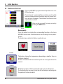
4.8 Touchscreen functions
The Leica ASP200 S is programmed and operated via a color
LCD touchscreen.
The instrument's control software contains an online help
feature including detailed information about all screen functions and error messages. The software functions are also
explained here in detail.
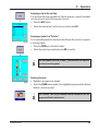
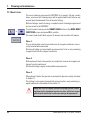
Help can be accessed from any screen by
pressing the HELP button.
Fig. 18
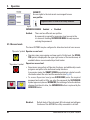
Button symbols
Press the button to activate the corresponding function on the Leica
ASP200 S touchscreen. All buttons have a uniform design for easy identification.
The buttons may contain text labels or graphical icons.
Enabled
The buttons change their appearance depending on whether they are
enabled or disabled.
A button is disabled if the function that it performs is not applicable at the
moment.
Disabled
Disabled icons have a thinner border than active ones as shown here.
If a disabled button is pressed, a help text will be displayed, explaining why
this particular button is disabled.
34
Instructions for Use V 1.4, RevE – 03/2013
4. Instrument Setup
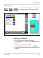
4.9 Checklist for initial operation
When the instrument is prepared to the point where it can be switched on, the menus listed
below have to be opened and the corresponding parameters configured.
For detailed instructions about the individual parameters, refer to the online help.
Screen display → Press button
→
→
→
→
→
→
→
→
→
→
→
or
→
→
→
→
Parameter selection
Set warning values for the age of the carbon
filter and the operating hours of the pressure
air pump.
Enter the instrument name and select the language.
Optionally, set up the printer.
Here, configure all the parameters as required,
particularly the wax bath temperature.
Check that the date and time are correct.
Enter the desired reagents and the threshold
values for the CHANGE REAGENT warning.
→
Assign a reagent to each station (bottle).
Fill the reagent containers.
Remote filling (SMART SCREENS)
Manual filling (REAGENT STATUS)
Create the required programs.
Both infiltration and cleaning programs can be
copied and modified.
→
Fig. 19
Leica ASP200 S
Assign your favorite programs to the Favorites
menu and, if desired, assign the end time and a
symbol for these programs.
35
4. Initial Operation
4.10 Switching off the instrument
If the instrument must be completely switched off or disconnected from the
power supply, please proceed as follows:
• Press MENU to switch to the MENU FUNCTIONS window.
• Press the EXIT APPLICATION button there.
A message appears stating that all data has been stored and the system is
being shut down.
Fig. 20
Once all data has been stored, the following message appears:
Fig. 21
You can now switch off the instrument with the ON/STOP switch on the
right of the instrument and with the ON/OFF switch on the rear panel of the
instrument (Fig. 4, 42).
Pressing the RESTART key restarts the instrument.
Notice!
The instrument is allowed to be switched off completely in this
way only. Otherwise, severe damage to the instrument's hardware
and loss of data can occur.
36
Instructions for Use V 1.4, RevE – 03/2013
5. Operation
5.1 Setting up the instrument parameters
→
From the start screen, press MENU to switch to the MENU FUNCTIONS
window, and press the MORE button there.
Fig. 23
Fig. 22
In the
MORE MENU FUNCTIONS
press
SYSTEM SETUP
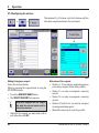
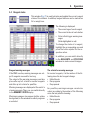
5.1.1System setup
The
SYSTEM SETUP
screen is divided up into five
selection fields:
• Program options
• Display/Buzzer
• Date/time
• Security
Fig. 24
Leica ASP200 S
• Instrument
37
5.Operation
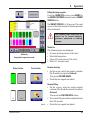
Fig. 25
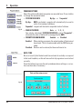
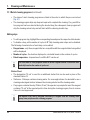
PROGRAM OPTIONS
Select the options with which programs are executed here. Press a button
to change the associated value.
• STATION SEQUENCE: By Age or Sequential
By Age -RMS is activated, reagents will automatically be used in
order of increasing cleanliness.
Sequential - reagents will be used in sequential order of stations.
• WAX BATH ORDER:
Auto or 1. ; 2. ; 3.
Can only be activated if STATION SEQUENCE is set to "Sequential" otherwise the order of baths will be managed by the RMS.
• PROMPT FOR NUM BLOCKS:
Enabled or Disabled
Enabled-When starting a program, the actual number of blocks must
be entered. This is recommended with the RMS being enabled.
Disabled - Number can be entered, but does not have to be.
DATE / TIME
Be sure to verify that the date and time entered do actually correspond
to the local time/date, as this will ensure that all programs are carried out
correctly.
Press the buttons to access the entry windows where settings or corrections can be made, if necessary.
Date and time setup screen
Fig. 26
Fig. 27
38
Instructions for Use V 1.4, RevE – 03/2013
5. Operation
DISPLAY/BUZZER:
• The number next to DISPLAY OFF indicates the remaining time (in min)
until the screen saver (after the last user action) is activated.
• The BUZZER VOLUME can be set between 1 and 10.
Fig. 28
INSTRUMENT
Press PARAFFIN BATH SET TEMP. to open the input screen (Fig. 30) for the
wax bath temperature.
Set the temperature according to the value required by the paraffin used.
Select the highest permissible temperature for the paraffin to ensure that a
minimum loss of temperature occurs when filling the retort.
Fig. 29
The RUN OPTIONS
displays the options with
which a program starts.
The options set apply for
ALL programs!
A printer option will be displayed only if a printer has
been configured for the
instrument.
The individual options are
described in Chap. 5.3.1.
Paraffin temperature and
run options screen
Fig. 30
Leica ASP200 S
39
5.Operation
SECURITY
Access rights to the instrument are managed here as
user profiles.
Supervisor mode is disabled in factory condition.
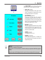
Fig. 31
SUPERVISOR MODE: Enabled or Disabled
Enabled-There are two different user profiles.
A password is required for supervisor level access to the
in- strument. Enabling SUPERVISOR MODE already requires
entering the password.
5.1.2Access levels
The Leica ASP200 S may be configured to allow two levels of user access.
"Operator" symbol Operator access level:
• Operators may run programs and view results. On this level, the OPERATOR symbol is displayed in the upper right corner of the touchscreen; all
enabled buttons are surrounded by a black border.
"Supervisor" symbol
→
Supervisor access level:
• Supervisors may perform all Operator functions, and additionally create
programs and perform the instrument setup functions.
In supervisor mode, the SMART SCREEN menu displays a status bar with
information about the retort and the wax baths (see Fig. 55)
• To access Supervisor level, press SUPERVISOR, enter the required
password and confirm. After you enter the password, the SUPERVISOR
symbol appears in place of OPERATOR, the outlining of all active buttons
changes from black to blue, the SUPERVISOR button is replaced by the
OPERATOR button.
Disabled -Default state of the instrument. All instrument and software
functions of the ASP200 S are fully accessible to all staff.
40
Instructions for Use V 1.4, RevE – 03/2013
5. Operation
LOCK MODE:Enabled or Disabled
In the Leica ASP200 S, there is a lock mode to
protect against operation by unauthorized persons.
Enabled:
The LOCK key is active in the menu functions.
A password is required for activation. If LOCK is
pressed, no keys can be enabled until the agreed
password is entered.
Disabled:
All functions are accessible as long as the
screen saver is active.
Fig. 32
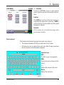
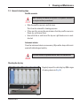
Entry keyboard
The keyboard is displayed any time text needs to be entered.
• The keyboard headline (1) tells you what kind of text to enter.
• 30 characters can be entered into each entry field, though sometimes
not all characters entered can be displayed.
Important keys
Shift:
To shift to upper case symbols.
AltGr:
Permits the entry of special characters.
<-- :
Deletes the previous character.
Delete:
Deletes the entire line.
1
Fig. 33
Leica ASP200 S
41
5.Operation
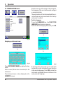
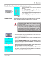
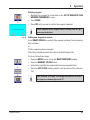
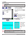
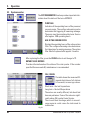
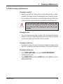
Use this menu to set the name of the instrument,
the language of the user interface and configure
a connected printer.
The serial number of the instrument and the current software version are entered at the factory
and cannot be edited.
5.1.3 INSTALLATION menu
→
→
Select a language
Press the LANGUAGE key, the SELECT THE
LANGUAGE selection menu appears.
Select the desired language there and press OK.
↓
Fig. 34
Assigning an instrument name
↓
↓
Fig. 35
Press INSTRUMENT NAME: to display the keyboard.
Enter a name (20 characters maximum) for the
instrument.
The instrument name is also displayed on the
FAVORITES screen.
42
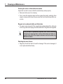
Fig. 36
A message box will prompt you to restart the
instrument in order to display the user interface
in the selected language. Press YES to restart the
instrument and display the user interface in the
newly selected language.
Instructions for Use V 1.4, RevE – 03/2013
5. Operation
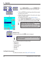
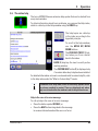
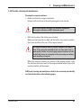
Setting the altitude of the installation location (in meters above sea level)
This is important as it affects the actual pressure in
the retort.
Press SITE ELEVATION (meters), enter the value in
the number field and press OK.
→
This parameter (in meters) must be entered to ensure
that the ASP200 S makes the appropriate corrections
when calculating the proper pressure or vacuum.
Fig. 37
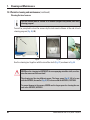
Upgrading software
New versions of the ASP200 S operating software are distributed on diskettes. These upgrade packages normally include 2 to 3 diskettes.
Do not attempt a software upgrade if you do not have all diskettes
of a package available.
Read the documentation in the upgrade package to find out how
to carry out the upgrade, as the included documentation may still
contain version-specific additional information, and to find out if
new/modified procedures, parameters or data are present that
have to be loaded or modified for the new software version to run.
1. First make a backup copy of the instrument's current data. To do so, you
need an empty, formatted diskette.
2. Insert the disk marked "Disk 1" (or similar) of the software upgrade into
the disk drive.
3. Press the UPGRADE SOFTWARE button. This is followed by two security
prompts that must both be answered with YES / OK. Afterwards, follow
the instructions on the screen.
When prompted, insert the disk labeled "Disk 2" into the disk drive. Follow
the same procedure for the other disks (if present).
4. After the update process is complete, the instrument software carries
out a restart – the screen shuts off and then restarts as if the instrument
had been switched off and switched on again.
↓
↓
Fig. 38
Leica ASP200 S
43
5.Operation
Configuring a printer
On the INSTALLATION screen press PRINTER TYPE to
display the list of the printers that can be connected.
→
→
• The Leica ASP200 S works with any printers that are compatible with commercial PCs.
• Connect the printer provided to the printer port using a
Centronics standard cable.
(For additional information, refer to Chap. 4.4, Fig. 9)
• In the SELECT THE PRINTER TYPE window, highlight the
printer that is connected to the instrument and press OK.
↓
If the printer driver you connected is not listed, try a
similar printer of the same manufacturer.
If this approach does not work, call Leica Technical
Service to have the required printer driver installed.
↓
Fig. 39
Printing run logs
Printing is possible when the PRINT symbol is displayed.
The printer icon is displayed only after a printer has been configured for the instrument.
The following lists and protocols can be printed:
• Reagent list
• Stations list
• Reagent status list
• All programs
• Run log
• Error log
Installing the laboratory help
For additional information, refer to Chap. 5.6 "The online help"
44
Instructions for Use V 1.4, RevE – 03/2013
5. Operation
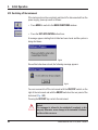
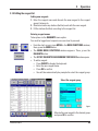
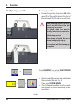
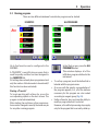
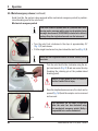
5.1.4Editing the reagent list
Adding new reagents
1. Enter the reagent name and allocate the new reagent to the reagent
group it belongs to.
2. Determine how many stations (bottles) work with the new reagent.
3. Fill the stations (bottles) according to the reagent list.
→
Entering reagent names
Takes place via the REAGENTS menu option.
You must be logged on at supervisor access level to proceed.
• From the start screen, press MENU in the MENU FUNCTIONS window;
there, press the MORE button.
• The MORE MENU FUNCTIONS window appears. There, press the
REAGENTS button.
• The SET UP REAGENTS AND WARNING THRESHOLDS window opens.
• To add a reagent:
• Press INSERT to display the keyboard.
• Enter the new reagent name.
• Press OK to confirm.
• You will then automatically be prompted to select the reagent group:
Select the reagent group
Fig. 41
Fig. 40
Leica ASP200 S
Allocate the new reagent to the desired group
and press OK to confirm.
45
5.Operation
Allocation of reagents to the correct reagent group is the basis for compatibility monitoring.
Allocation to the wrong reagent group can lead to reagent cross contamination.
Changeable parameters
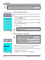
Entering / modifying reagent thresholds
If warning thresholds are required for a certain reagent, enter them as follows:
• Highlight the reagent to be modified, either by pressing the reagent name
or using the UP/DOWN buttons.
• Press the header of the parameter to be changed; the corresponding
entry screen appears.
• Enter a new threshold value or - if no warning is desired - press CLEAR
to remove the threshold altogether.
• Press OK to confirm.
The respective threshold value applies for all reagent stations containing the same reagent.
Fig. 42
Changing reagent names or reagent groups
If a reagent is already used in a program, it can neither be renamed
nor can it be allocated to another reagent group!
The corresponding symbols will be disabled (i.e. they will not be
surrounded by a blue border).
If a reagent is renamed, all stations and programs linked to that reagent need to be reedited as well!
• Highlight the reagent the name or group of which you wish to change.
• Press the corresponding button symbol in the headline.
• In the entry window (or via the keyboard), enter the new reagent group
allocation / the new reagent name.
• Press OK to save the new reagent group / reagent name.
Fig. 43
46
Instructions for Use V 1.4, RevE – 03/2013
5. Operation
Deleting reagents
• Highlight the reagent to be deleted in the SET UP REAGENTS AND
WARNING THRESHOLDS screen.
• Press CLEAR.
• Press YES in the screen to confirm the reagent is deleted.
↓
Please remember that a reagent which is already used in a program cannot be deleted.
Fig. 44
↓
↓
Leica ASP200 S
Adding new reagents to stations
Go to SMART SCREEN to remote-fill the reagent container from an external
bulk container
or
fill the reagent container manually.
After filling a bottle manually the bottle must be defined as full.
To do so, follow these steps:
• Press the MENU icon to call up the MENU FUNCTIONS window.
• Press the REAGENT STATUS button.
• In the table, highlight the reagent that has been manually filled.
• Press the SET AS FULL button symbol to set the status of the station to
"full".
Upon activation of the RMS, all warning thresholds for the selected reagent are automatically reset to "0".
47
5.Operation
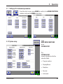
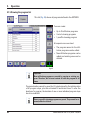
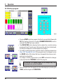
5.1.5Viewing the program list
→
This list (Fig. 45) shows all programs defined in the ASP200 S.
You can create:
• Up to 15 infiltration programs
• 3 retort cleaning programs
• 1 paraffin cleaning program
At supervisor access level:
• The program names for the infiltration programs can be edited.
• New infiltration programs can be
added and existing ones can be
deleted.
Fig. 45
Important!
New infiltration programs are created by copying an existing program. Therefore, the list must contain at least one program at all
times.
Program duration cannot be specified. It is determined by the total duration
of all program steps, plus the estimated fill and drain times. To alter the
duration of a program, the duration of one or more individual program steps
has to be modified.
Retort or paraffin cleaning programs are preset. They cannot be renamed, added or deleted.
48
Instructions for Use V 1.4, RevE – 03/2013
5. Operation
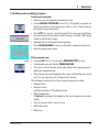
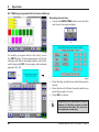
5.1.6Adding and/or modifying programs
Creating a new program
• Make sure you are logged on at supervisor level.
• In the VIEW/EDIT PROGRAMS screen (Fig. 45) highlight a program as
similar as possible to the program you wish to create. (This minimizes
the number of operating steps).
• Press COPY to copy the selected program. The new program will have
the same name as the program copied, however, the figure "(2)" will be
added to indicate the change.
• Highlight the line containing the new program.
• Press PROGRAM NAME at the top of the table to display the keyboard.
• Enter the new program name.
Fig. 46
Leica ASP200 S
Editing program steps
• Pressing EDIT (in Fig. 45) calls up the PROGRAM STEPS screen.
• In the headline you will find the PROGRAM NAME.
• The colors on the left border of the table indicate the reagent groups to
which the reagents belong.
• The program steps are displayed in the order in which they are carried
out. For each program, up to 13 steps can be defined.
The following characteristics of each program step can be edited:
• Reagent name.
• Duration of step
(with the exception of fill and drain steps).
• Retort temperature
(if "Ambient" is selected, the display for the retort temperature remains
empty).
• Type of pressure and/or vacuum cycle
• Retort drain time.
• Delay step.
49
5.Operation
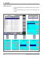
Editing program steps
• To edit a step, highlight the corresponding line and press the respective
headline.
• In the entry windows that pop up, enter / select the program step
settings.
↓
↓
↓
↓
↓
Fig. 47
50
Instructions for Use V 1.4, RevE – 03/2013
5. Operation
Editing program steps (continued)
Setting a delay step
A delay step is a step that is extended to ensure that a program will finish
at a specified time.
• Highlight the program step you wish to define as delay step.
• Touch the DELAY button.
The delay symbol is moved to the selected step, thus defining the step
as delay step.
Copying program steps
• Highlight the step you wish to copy.
• Touch the COPY button.
• If required, modify properties of the step.
Remember that a program step cannot be copied if the program already contains the maximum number of 13 steps.
• Use the MOVE UP / MOVE DOWN buttons to move program steps up or
down within an existing program without having to recreate those steps.
Deleting program steps
To delete a step from a program:
• Highlight the step you wish to delete.
• Press CLEAR.
Remember that it is not possible to delete a step from a program
containing only one single step.
Programs must consist of at least one step.
Leica ASP200 S
51
5.Operation
5.1.7Favorites
Up to five favorites can be configured in the ASP200 S.
Favorites can be programmed so that they:
• end "as soon as possible" (ASAP) or
• end at a predefined time.
↓
Fig. 48
Adding/modifying a Favorite
• Select the program line to be modified.
• Touch the PROGRAMS button.
• Select the program you want and press OK to confirm.
↓
Setting the end time
• Press the END TIME button.
• In the input window, specify the end time using 24-hour notation. Select
ASAP if the program is to be terminated without a waiting time.
• Confirm the end time with OK.
Fig. 49
52
If an end time is assigned to a Favorite, the delay step is prolonged
by the program so that the program is terminated at exactly the
preselected time.
Instructions for Use V 1.4, RevE – 03/2013
5. Operation
Assigning a day for the end time
If an end time has been assigned to a Favorite program, a specific weekday
can also be set on which the program is to end.
• Press the DAY button.
• Select the desired day from the list and confirm with OK.
↓
Fig. 50
Assigning a symbol to a "Favorite"
A corresponding symbol is displayed, which helps the operator recognize
a certain program.
• Press the ICON key in the table header.
• Select the symbol you want and press OK to confirm.
↓
The first symbol in the list is empty – you can select this option if
you do not want any symbol.
Fig. 51
Deleting a Favorite
• Highlight a program to be deleted.
• Touch the CLEAR button symbol. The highlighted program will be deleted
without a security prompt.
The "Favorite" will only be removed from the FAVORITES list, the
program itself will not be deleted.
Leica ASP200 S
53
5.Operation
5.1.8Configuring the stations
→
→
This window (Fig. 52) shows a list of all stations with the
allocated reagents defined in the instrument.
↓
Fig. 52
Adding/changing a reagent
Select the desired station.
Either by pressing the reagent name or using the
UP/DOWN buttons.
• Touch the REAGENT NAME button.
• The SELECT REAGENT field appears.
Only those reagents that are compatible with the selected station will be
offered for selection.
Allocation of the reagents
• Stations 1 – 10 can only be assigned specimen
processing reagents (other than paraffin).
• Station 11 can only be assigned a cleaning
solvent.
• Station 12 can only be assigned a cleaning
alcohol.
• Stations 13 and 13-ext. can only be assigned
cleaning water/detergents.
• Wax baths may only be used for paraffin.
• Highlight the reagent you want and confirm
your selection with OK.
54
Instructions for Use V 1.4, RevE – 03/2013
5. Operation
5.1.9Reagent groups
→
→
In this window (Fig. 53), the colors used in the graphical
program display for each reagent group are displayed.
↓
Fig. 53
Changing the color of a reagent group
• Highlight the line containing the reagent to be modified.
• Press the COLOR button in the table header; the SELECT COLOR window
appears.
• Select the color you want and confirm with OK.
• To exit the display without changing any colors, select CANCEL.
• The newly configured color will now be used on all stations to represent
the reagent.
Leica ASP200 S
55
5.Operation
5.2 Reagent handling
5.2.1Draining/filling reagents (other than paraffin)
↓
↓
1. Manually changing the reagents
• Remove the appropriate reagent container from the reagent cabinet,
remove the bottle screw cap.
• Drain/refill the reagent by pouring to/from a bulk container. Use the
included funnel for clean filling.
• On the REAGENT STATUS screen, verify correct allocation and set the
reagent container as full.
2. Use the "Remote Fill / Drain" features
• Connect the hose for remote filling/draining
as shown in Fig. 6 to the connection (7).
7
Important!
Press the connection of the hose firmly
into the holder until you can clearly
hear it click.
• Hook the other end of the hose into the bulk
container that you are emptying or filling.
Fig. 54
While performing a reagent fill/drain, ensure that the remote fill/
drain hose is securely placed in the remote container and is not removed from the container until the operation is fully completed
Finally, pressurized air is used to clear the hose after each fill /
drain so that no dirt remains.
The hose should therefore not be removed from the bulk container
until this cleaning step is complete.
56
Instructions for Use V 1.4, RevE – 03/2013
5. Operation
Filling/draining reagents
From the FAVORITES screen, press MENU. In
the MENU FUNCTIONS window, tap the SMART
SCREEN button.
→
The SMART SCREEN (Fig. 55) pops up. The smart
screen is the initial screen for manual operation
of the instrument.
The following steps should only be
carried out by trained laboratory
personnel, experienced in handling
reagents.
Status bar
The following values are displayed.
• Pressure and temperature of the retort
• Wax bath temperature
• Value of the level sensor of the retort
• Retort lid - closed or open
Status bar,
displayed in supervisor mode.
Fig. 55
Select station
Remote draining
• On the screen, select the reagent container
(No. 3) and the receptacle (External).
Then press STATION DRAIN.
• Check that no reagent has leaked.
Press button
Fig. 56
Leica ASP200 S
Remote filling
• On the screen, select an empty reagent
container (No. 3) and the external receptacle
(External).
Then press the STATION REFILL button.
• The remote filling should be completed in less
than 170 seconds.
• Check that no reagent has leaked.
57
5.Operation
5.2.2Replacing the paraffin
Draining the paraffin
• Connect the paraffin drain hose (36) to the
spout (17) of the paraffin drain at the front of
the instrument (Fig. 57) and into a catch tank.
17
When connecting the hose, be sure to
press it onto the O-rings of the drain
opening as far as it will go.
The paraffin drain hose must be
securely hooked into the external receptacle and remain there through the
entire drainage process.
When drainage is finished, the hose is
cleaned automatically using air.
Do not remove the hose from the external receptacle until this cleaning step
is complete.
36
Fig. 57
From FAVORITES, call up the SMART SCREEN
screen. (see previous chapter)
→
+
• Select the paraffin reservoir to be emptied and
the receptacle (External, Fig. 58).
Then, press STATION DRAIN....
• This is followed by multiple security prompts
that you have to confirm individually in order
to continue.
→
Fig. 58
58
Instructions for Use V 1.4, RevE – 03/2013
5. Operation
• Fill the paraffin reservoir to the brim (Fig. 60, 1)
with paraffin pellets. This corresponds to approx. 3.5 kg/bath (Leica Histowax pellets).
• Press BACK and REAGENT STATUS to switch
to the status table (Fig. 59). Select the filled
wax bath and press the SET AS FULL button.
• After approx. 90 min, add another 0.5 kg of
paraffin pellets.
• Do not insert the baffle plate during the heating
phase.
• The pellets need a total melting time of approx.
10 hours.
Filling with paraffin pellets
→
→
Important!
The level in a wax bath must NEVER
fall below the mark for minimum level
(Fig. 60, 2).
Fig. 59
• Replace the baffle plate when the paraffin is
melted.
1
Software control
• After refilling with paraffin pellets, the
ASP200 S does not allow you to run any programs until the paraffin is completely melted.
The software calculates the amount of time
required for melting the paraffin and does not
start a program until it is sure that the paraffin
will have melted at the time of the first paraffin
cut.
2
Fig. 60
Leica ASP200 S
59
5.Operation
Filling with liquid paraffin
The temperature of filled liquid paraffin must not be greater than 70 °C to prevent damage to the
thermal fuse.
→
• If filling with already melted paraffin, the liquid
level must not exceed the MAX level mark (see
Fig. 60, 1) in the paraffin reservoir.
• After a paraffin reservoir is filled with paraffin, it must be marked as full in the REAGENT
STATUS table.
→
Fig. 61
Software control
If the instrument has been filled
with liquid paraffin, the instrument's
internal calculation of the melting
time can be disabled.
To do so, in supervisor mode, open the
SERVICE FUNCTIONS (Fig. 61) window.
Press PARAFFIN MELTING.
↓
→ →
A safety prompt appears that you have to
confirm with YES.
In the time window,
enter the desired delay time and confirm
with OK.
Fig. 62
Change the delay time only if you are absolutely sure that the entered time is correct.
If the instrument attempts to run a paraffin step with paraffin that is not completely melted,
substantial faults and malfunctions may result.
60
Instructions for Use V 1.4, RevE – 03/2013
5. Operation
5.3 Running programs
There are two different windows from which a program can be started:
ALL PROGRAMS
FAVORITES
Fig. 63
Fig. 64
Up to five favorites can be configured in the
ASP200 S.
A "FAVORITE" is an infiltration program that is
used frequently and thus has been assigned to
the FAVORITES list.
All settings have already been programmed and
only the number of blocks needs to be entered (if
this function has been activated).
In the Start screen, press the ALL
PROGRAMS button.
This window displays all of the
infiltration programs defined in the
instrument.
Starting a "Favorite"
To begin working with a Favorite, press the
corresponding symbol on the start screen. The
program is started immediately.
After starting, the end time or other program options can be changed in exactly the same way as
for any other running program.
Leica ASP200 S
• To call up a program, touch the button that is
labeled with the program name.
• A screen with the graphic representation of
the program appears; in it, all of the stations
necessary for this program are color coded
according to reagent group (Fig. 65).
• Unlike a Favorite, here you have the ability to
modify a program before it is started.
However, all modified processing steps apply
only for the program that is currently called up.
61
5.Operation
5.3.1Editing a program that has been called up.
Resetting the end time:
• Touch the FINISH TIME button and reset the
end time in the input window.
↓
Fig. 65
To modify a program before the start, press
the EDIT button. A message appears that the
changes will affect running programs only. After
confirming with YES, the program edit window
appears (Fig. 66).
→
↓
Fig. 67
• Enter the day on which you want the program
to end.
• Enter the time (in 24-hour format) at which you
want the program to end.
• Press OK to confirm.
Programs can be started up to 6 days in
advance. So that the program is ended
at the defined date/time, the delay step
is lengthened accordingly.
Fig. 66
62
Instructions for Use V 1.4, RevE – 03/2013
5. Operation
The RUN OPTIONS function displays the options
with which the current program is started.
• LEVEL TEST enabled:
The lower level sensor in the retort is activated. The program is stopped with an error
message if the level is not reached.
↓
• WAVE MOTION activated:
During each infiltration step, the reagent is
periodically pumped from the bottle to the retort and back to achieve a more evenly mixed
blend. The first pump step begins after 16 min,
afterwards regularly after 12 min.
• PRE-TEST activated:
After the program is started, the retort is filled
and drained with the first reagent in the infiltration program (to test whether all lines and
valves are unobstructed).
• STIRRER activated:
The magnetic stirrer is on.
• PRINTER, if activated:
At the end of the program, a complete run
log covering the entire program execution is
output at the printer.
Fig. 68
Important!
The options set apply for ALL programs!
All run options can be deactivated or activated according to requirements while the program is
running.
The printer option will be displayed only if a printer has been configured for the instrument.
Leica ASP200 S
63
5.Operation
5.3.2Starting a program
↓
Fig. 70
Fig. 69
→
• Pressing START starts the program. Confirm the prompt that follows with
OK. The number of blocks to be edited (NUMBER OF BLOCKS) must be
entered if the RMS has been enabled.
• The FINISH TIME button displays the time when the currently running
program will end. If events occur that cause the end time to be delayed,
the end time display here will be updated accordingly.
• To modify a running program or open the retort to reload specimens (see
Chap. 5.3.3 "Opening the retort"), the program has to be stopped - press
the PAUSE button. All buttons that have changeable functions are activated and can be edited.
To change or delete program steps, press EDIT and make the changes
in the input window. CONTINUE restarts the program.
The end time of a running program can be changed only if the
delay step has not yet been completed.
→
64
• You can switch from the graphical to the table display by touching the
TABLE, and back again with GRAPHICAL.
Instructions for Use V 1.4, RevE – 03/2013
5. Operation
5.3.3Opening the retort during a program interruption
The signal tone and the 10-second waiting time occur each time the retort is unlocked!
For this reason, we recommend only locking the retort before starting a program or before cleaning in order to prevent unnecessary waiting times.
• To unlock the retort, turn the lever for locking/unlocking (Fig. 71) approximately 45° clockwise
(Fig. 72) and release the lever.
A signal tone sounds for about 10 seconds. The reagent level in the retort drops by about
10 mm during this time.
This prevents the reagents from spilling out of the retort when it is opened.
• After the signal tone stops, turn the lever all the way to the right (Fig. 73) and open the retort lid.
Approx. 45°
Fig. 71
Fig. 72
Fig. 73
5.3.4Retort emergency release
The retort lock is equipped with a safety system for unlocking the retort.
Electronic emergency unlock
• If the retort cannot be opened after 10 seconds, press the "EXIT APPLICATION" button and
follow the instructions in Chap. 4.10.
• After shutting down (see Chap. 4.10, Fig. 20 and 21) switch off the instrument's power switch
(Fig. 4, 42). The retort can then be opened and the samples can be removed.
Leica ASP200 S
65
5.Operation
5.3.4Retort emergency release (continued)
Aside from this, the system is also equipped with a mechanical emergency unlock (a predetermined breaking point in the retort lock).
Mechanical emergency unlock
If the retort cannot be opened while in a powered-down state,
the stop can be overcome and the retort can be unlocked using
the single-head wrench (14 0330 50891) included in the delivery
package. Keep the single-head wrench near the instrument!
Approx. 45°
1
• Turn the retort lock clockwise to the stop at approximately 45 °
(Fig. 74, 1) and release.
• Put the single-head wrench in place below the retort lock (Fig. 75, 2).
Ensure that the single-head wrench is seated securely on the
retort lock.
• Turn the retort lock further clockwise using the single-head wrench (Fig. 75, 3) and overcome the stop
(breaking the retaining pin at the predetermined
breaking point).
3
2
Fig. 74
Fig. 75
Approx. 45°
4
Notice! A large amount of force is needed to
do this. Caution! Risk of injury.
• Once the stop has been overcome, the retort can be
opened (Fig. 76, 4) and the samples can be removed
and secured.
The instrument can no longer be operated
after the retort has been unlocked using
the mechanical emergency unlock. Notify a
responsible Leica service technician!
Fig. 76
66
Instructions for Use V 1.4, RevE – 03/2013
5. Operation
5.4 Reagent status
→
This window (Fig. 77) is used to display and update the current reagent
status of the stations. In addition, reagent stations can be marked as
full or empty here.
The following is displayed:
• The current age of each reagent
• The current status of each station
• Criteria that trigger warning messages
(fields highlighted in red)
To change the status of a reagent,
highlight the corresponding row and
press the button symbol for the respective action.
In addition, you can switch directly
to the REAGENTS and STATIONS
windows to make current changes.
Fig. 77
Reagent warning messages
If the RMS is active, warning messages are output if reagents are used for too long.
The output of the warning messages can take
place after up to 3 criteria for normal reagents
and after up to 6 criteria for paraffins.
Warning messages are displayed at the end of a
cleaning program. Then, you can switch directly
to the REAGENT STATUS display.
Warning messages also appear (with a yellow
background) in the windows in which programs
are started.
Leica ASP200 S
The criteria for warning messages
For normal reagents, it is the number of the following since the last reagent change:
• Edited blocks
• Run programs
• Days passed
For paraffins, warning messages can also be
output according to the number of the following
since the last paraffin cleaning:
• Edited blocks
• Run programs
• Days passed
67
5.Operation
5.5 System monitor
→
→
The SYSTEM MONITOR function provides important information about the status of the Leica ASP200 S.
PUMP AGE:
Indication of the operating hours of the pressure/
vacuum pump. The configured warning value
determines the triggering of a warning message.
The pump must be maintained by Leica Service
after approx. 1000 operating hours.
AGE OF THE CARBON FILTER:
Displays the operating hours of the active carbon
filter. The configured warning value determines
the triggering of a warning message. The carbon
filter must be replaced after approx. 3 months.
Fig. 78
After replacing the filter, press the CLEAR button to set the age to "0".
ROTARY VALVE RETRIES:
Provides information about the status of the rotary valve. If the number
specified there exceeds 50, maintenance is recommended.
FILL / DRAIN:
The table shows the measured filling and drain times of all stations
(in seconds) as average values.
Fig. 79
68
Short-term = the last 5 operations
Long-term = the last 20 operations
The values are usually different, but should not
have any extremes. If one of the values is significantly above 250, contact Leica Service.
There could be a blockage, which in a worstcase scenario could cause the instrument to
malfunction.
Instructions for Use V 1.4, RevE – 03/2013
5. Operation
5.6 The online help
The Leica ASP200 S has an extensive help system that can be started from
every main window.
To obtain information about basic problems, you can use the Help index,
which is called up in the Help window using the INDEX key.
The help topics are called up
in the index according to the
hyperlink principle.
To scroll in the help window,
use the MOVE UP/ MOVE
DOWN buttons.
The PREVIOUS TOPIC (1) button takes you from a detail
back to the index.
2
1
3
Fig. 80
BACK (2) displays the most recently active
working window.
The CUSTOM HELP button (3) is displayed only
if a custom laboratory help has been installed.
For detailed information on how to create and install a custom help file, refer
to the help index under the "What is Custom Help?" header.
In addition to the help index, there are other help options which
are always provided in context. These are displayed only when
help is accessed within the window in which the problem occurs.
Help in the case of an error message
To call up help in the case of an error message:
• Press the button symbol DETAILS, or
• Press the HELP button integrated in the message
to receive information about the source of error.
Leica ASP200 S
69
6.Troubleshooting
6.1General
The Leica ASP200 S is equipped with a cutting-edge fault detection and
troubleshooting system.
When detecting a malfunction, the instrument provides the operator with
detailed error messages and corresponding steps to take via the screen.
For all error states, the instrument takes corrective measures to
protect the specimens, except in such cases where continued
functioning of the instrument would be possible only under hazardous operating conditions.
→
• All processes are recorded in detail in the "Run Log."
To inspect the processes, the Run Log file can be opened by pressing
the MENU and RUN LOG symbols.
6.2 Power failure
Power failure during an infiltration program
• If a power failure occurs during an ongoing infiltration program, the
Leica ASP200 S calculates the power failure duration into the total duration of the step taking place; in other words, the respective step is not
lengthened due to the power failure.
• If the power failure continues for longer than the remaining duration of
the step during which it occurred, the Leica ASP200 S does not shorten
the following steps.
• If, on account of a power failure, the paraffin temperature is reduced to
the point that the paraffin is no longer suitable for continuing the ongoing program, the Leica ASP200 S builds in a delay time sufficient to bring
the paraffin back to a suitable operating temperature before the paraffin
step.
Power failure during a retort or paraffin cleaning program
• If a retort or paraffin cleaning program is running during a power failure,
the total program duration is lengthened by the duration of the power
failure. This is to make sure that the cleaning results are not impaired.
70
Instructions for Use V 1.4, RevE – 03/2013
6. Troubleshooting
6.3Troubleshooting
If a problem occurs in the Leica ASP200 S, take the following steps to diagnose the problem:
→
• Check for error messages indicating the nature of the problem.
• If an error message is displayed, press the Help button on the message
for any information relating to the cause.
• Check the Run Log for any messages that indicate the nature of the failure. If the failure occurred during a program run, check the Run Log for
an indication of whether the failure occurred during the fill, processing
or drain cycles, and the reagent container in use at the time.
Use the SMART SCREEN functions to individually test operations
such as fill, drain, pressurizing and evacuation operations.
Power failures
If there is evidence of power to the instrument:
• Verify that the power plug is plugged into the socket and that the socket
is switched ON.
• Check whether the bridge cable is plugged in properly.
• Verify that the power switches on the rear of the instrument (adjacent to
the power lead) and on the side of the instrument are both switched ON.
• Messages indicating that there has been a partial power failure indicate
that power has been lost to the heaters, but not to the main control electronics. Carry out the above steps to identify the nature of the problem.
If you cannot identify the problem by carrying out the above listed
steps, call Leica Technical Service.
Leica ASP200 S
71
6.Troubleshooting
6.4 Typical fill or drain problems
Fill and drain problems may be due to several causes:
1. There is insufficient reagent
• Verify that the fill level of the reagent containers and the paraffin
reservoirs is sufficient.
2. Insufficient pressure or vacuum
The instrument is unable to create sufficient vacuum (for a fill) or pressure (for a drain) in the retort.
• Verify that the reagent container in question is correctly inserted in
the reagent cabinet.
• Verify that all reagent containers are fully pushed home into their
sockets.
• Check whether there is some debris under the retort lid seal causing a leak.
3. There is a blockage in the air or reagent lines
Blockages in the reagent lines are typically caused by paraffin or tissue debris. If there is reagent in the retort that cannot be drained, try to
remove the blockage as follows:
• Heat the retort to the maximum possible temperature (consistent
with the reagent currently in the retort, if any). Leave the retort at
this temperature for at least 15 minutes.
• While the retort is at maximum temperature, attempt to fill or drain.
• If there is no reagent in the retort:
Run the extended retort cleaning program. Use the maximum settings for number of clean cycles and temperature (consistent with
the type of reagents/solvents used in the clean program).
If you cannot eliminate the problem by carrying out the above listed steps, call Leica Technical Service before attempting to run any
further programs.
72
Instructions for Use V 1.4, RevE – 03/2013
7. Cleaning and Maintenance
7.1 Clean programs
→
→
The cleaning programs are at the end of the list of all programs (Fig. 45). To display a clean program, highlight the
respective line and press EDIT.
Three retort cleaning programs and a paraffin cleaning program are defined in the ASP200 S.
Clean programs cannot be copied or deleted.
Replacement schedule for cleaning reagents:
The cleaning reagents (cleaning xylene and cleaning alcohol) must be replaced weekly (refer
to Chapter 3.6.1).
If fatty tissue, bloody tissue, biopsy sponges or the like are processed, both the reagents and
the cleaning reagents must be replaced more frequently.
7.1.1Retort cleaning programs
A cleaning program comprises a
minimum of three and a maximum
of four steps:
1.Solvent
1 step from station 11
2. Cleaning alcohol
1 step from station 12
3. Cleaning water
1 step from station 13
Optional between steps 2 and 3:
Cleaning water/detergent
1 step from station 13-ext.
Fig. 81
Leica ASP200 S
73
7. Cleaning and Maintenance
7.1.1Retort cleaning programs (continued)
• The steps of retort cleaning programs are listed in the order in which they are carried out
(Fig. 81).
• The cleaning program skips any steps not required to complete the cleaning. If, e.g. an infiltration program has been aborted during the alcohol step, the subsequent clean program will
skip the cleaning solvent step and will start with the cleaning alcohol step.
Editing steps
• To edit a program step, highlight the corresponding line and press the respective table header.
• To disable a step, set the number of cycles to "0". Only cleaning water steps can be disabled.
The following characteristics of each step can be edited:
• Reagent name - only those reagents that are compatible with the reagent station being edited
will be displayed.
• Number of cycles - the duration displayed is calculated based on the number of cycles.
• Retort temperature - temperatures from 50 to 65 °C can be set.
The finish times of clean programs cannot be edited. Program duration is calculated automatically based on the number of cycles set.
Station 13-ext
• The designation "13-ext" is used for an additional station that can be used in place of the
standard station 13.
• Station no. 13 always contains cleaning water. For some applications it is desirable to use a
cleaning water/agent mixture between the cleaning alcohol and the cleaning water.
• If a program contains the step "Station 13-ext", the operator is prompted to insert the reagent
container "13-ext" at the required point in time during the cleaning program, then to remove
it once it is no longer used.
The station 13-ext can be assigned exclusively to reagents from the cleaning water
group. It may only be used for cleaning programs.
74
Instructions for Use V 1.4, RevE – 03/2013
7. Cleaning and Maintenance
7.1.2Paraffin cleaning
It is possible to clean used paraffin of solvent
residues (xylene) in the Leica ASP200 S.
↓
To do so, select the paraffin bath for which the
paraffin should be cleaned in the CLEANING
PROGRAMS menu.
If the last reagent in the retort is not compatible
with paraffin, carry out a retort cleaning first.
↓
The following steps are taken during the paraffin
cleaning:
• The paraffin is pumped into the retort.
• There it is heated to the highest possible temperature.
• The retort is put under vacuum, causing the
solvent vapors to be drawn out of the paraffin.
Fig. 82
→
The duration of the paraffin cleaning process is
programmable.
To do so, follow these steps:
• In the PROGRAMS menu, select the PARAFFIN
CLEANING line and press the EDIT button.
• In the entry window, specify the duration for
the cleaning program.
The recommended time frame is one hour.
• Confirm the time specification with OK.
→
Fig. 83
Leica ASP200 S
75
7. Cleaning and maintenance
7.1.3Smart clean
→
The smart cleaning prepares the ASP200 S for transport. During a smart
clean, a series of air cleaning steps will be applied which will remove any
excess liquid (condensate) from all internal tubing.
Before starting a smart cleaning, a complete retort cleaning program must
be carried out in the ASP200 S.
To start a smart clean, press the SMART CLEAN button on the MORE MENU
FUNCTIONS screen and press OK to confirm.
The smart clean itself takes approx. 15 minutes and consists of 3 phases:
Phase 1:
Prior to starting the smart clean make sure all reagent containers are correctly inserted and connected.
All internal tubing is cleaned with compressed air to force any remaining
reagents back into the reagent containers.
Phase 2:
Before phase 2 starts, the operator is prompted to remove all reagent containers from the instrument.
All internal tubing is again cleaned with compressed air.
Phase 3:
When phase 3 starts, the operator is prompted to place an empty container
in station 11.
The tubing is once again cleaned with pressurized air; any remaining reagent residues are forced back into station 11.
Empty and clean all reagent containers thoroughly before reinserting them into the instrument to make sure there will be no reagent
spills from the bottles that could cause damage during transport.
76
Instructions for Use V 1.4, RevE – 03/2013
7. Cleaning and Maintenance
7.2 General cleaning steps
Paraffin reservoirs
Work carefully! Be careful as the walls of the paraffin reservoirs
are very hot and may cause burns!
• Wipe the paraffin reservoirs and lids clean.
The lid can be removed for cleaning purposes.
• If they are dirty, remove the wax strainers from the paraffin reservoirs.
Clean, dry, and reinsert them.
• Ensure that the air vent hole at the top rear right hand corner is unobstructed.
Instrument exterior
Clean the instrument exterior as necessary. Wipe with a damp cloth moistened with mild detergent and dry.
Do not use solvents on painted surfaces and/or the touchscreen!
Checking the drip tray
Regularly inspect the collecting tray (16) for signs
of leaking chemicals (Fig. 84).
16
Fig. 84
Leica ASP200 S
77
7. Cleaning and Maintenance
Draining the condensate container
• Remove, empty, and reinsert the blue condensate container (Fig. 85).
Dispose of waste solvents with care
according to local regulations and the
waste management policy of the company or institution.
14
Fig. 85
Replacing the active carbon filter
• The life of the active carbon filter will depend
on the reagent types used and the frequency
of vacuum cycles.
• The filter (13) should be replaced at least every
3 months. (Fig. 86)
After replacing the filter, open the SMART
MONITOR menu to reset the filter age to "0".
For additional information, refer to Chap. 5.5
• We recommend a smart clean prior to changing the filter.
13
Fig. 86
Filter label
78
When inserting the new filter, make
sure that it is inserted with the correct side up, as specified on the label
on the front side of the filter.The arrow
must point upwards.
Instructions for Use V 1.4, RevE – 03/2013
7. Cleaning and Maintenance
7.2.1Daily cleaning and maintenance
Cleaning the retort lid
• Remove wax from the inside of the retort lid with the plastic scraper
provided. Thoroughly remove all wax deposits from around the lid seal.
• For convenience, the lid may be removed during cleaning. Lift the lid to
a vertical position, release the hinge lock and pull the lid toward you.
Only use the plastic scraper provided when cleaning the retort
lid and seal to avoid damage to the retort lid seal and to the PTFE
coating on the retort lid. Do not damage the edges of the seal with
the scraper.
Cleaning the retort
• The retort may be wiped clean using a cloth moistened with solvent
(xylene or alcohol) or mild detergent. In particular, make sure that the
air vent holes at the top front of the retort are not dirty.
Cleaning the retort sieve
• Use alcohol or xylene to clean the strainer located at the bottom of the
retort. For convenience, the sieve may be taken out to remove all solid dirt.
Cleaning the touchscreen
• On the MENU FUNCTIONS screen press CLEAN TOUCHSCREEN.
• Clean the touchscreen.
• Press ENABLE EXIT to enable the BACK button. Press BACK to return to
MENU FUNCTIONS.
Leica ASP200 S
79
7. Cleaning and Maintenance
Cleaning the surface of the infiltration module
Important in order to ensure that the seals always seal properly.
• Remove both covers for cleaning.
• First, clean the stainless steel surface using the plastic spatulas, then
wipe to remove all dirt particles around the retort and the paraffin reservoirs.
Reagent and condensate bottle seal lubrication
• To ensure easy removal of the reagent and condensate bottles, lubricate
the O-ring seals on the plug-in nozzles with the O-ring lubricant supplied.
This procedure is particularly important with bottles containing
chloroform. O-rings that have not been lubricated swell when exposed to chloroform. The reagent containers can then become very
difficult to remove.
Checking the retort lid seal
• Regularly check the retort lid seal for damage. If the seal is damaged, it
must replaced without delay.
80
Instructions for Use V 1.4, RevE – 03/2013
7. Cleaning and Maintenance
7.2.2Periodic cleaning and maintenance
Cleaning the reagent containers
• Empty and clean the reagent containers.
Using a bottle brush and a laboratory detergent in warm water.
Never clean reagent containers in an automatic dishwasher.
The reagent containers are NOT dishwasher-proof!
• Refill and reconnect the bottles once cleaned.
Make sure the bottle lids are tight and the bottles are properly seated in
their home position at the rear of the reagent module.
The reagent containers must be properly engaged in the home position in the connection manifolds at the rear inner wall of the reagent module. Failure to correctly plug reagent containers into the
manifold will cause an interruption to the processing run and may
result in spilling of reagents.
While the reagent containers are outside of the reagent module, wipe
the stainless steel inner walls of the reagent module with a damp cloth
moistened with a mild detergent.
Additional cleaning and maintenance tasks to be carried out periodically
are listed in the table on the following pages.
Leica ASP200 S
81
7. Cleaning and Maintenance
7.2.2Periodic cleaning and maintenance (continued)
Cleaning the level sensors
The level sensors must be cleaned of all residues (reagents and paraffin) after every
cleaning program!
You will be prompted to clean the sensors by the instrument software at the end of each
cleaning program (Fig. 88, 44).
45
44
46
47
Fig. 87
Fig. 88
Fig. 89
Use the cleaning tool together with the microfiber cloth (Fig. 87) as shown in Fig. 89.
NEVER use the cleaning tool WITHOUT the accompanying microfiber cloth, as otherwise the sensors will be scratched!
The cleaning tool has two different spoons. The larger spoon (Fig. 87, 46) is for use
with the ASP6025, the smaller (Fig. 87, 47) is for use with the ASP200 S / ASP300 S.
To prevent damage to the sensors, NEVER use the larger spoon for cleaning the sensors in the ASP200 S / ASP300 S.
82
Instructions for Use V 1.4, RevE – 03/2013
7. Cleaning and Maintenance
7.3 Checklist for preventive maintenance
Step
Daily
Lubricate the O-rings of the reagent container and check them for damage.
Monthly
every
3 months
*
* During remote filling
and draining
After exiting the retort cleaning program,
wipe the retort and cover dry.
Clean the outer surfaces of the instrument
with a soft cloth and a very small amount
of xylene.
Check the retort filter screen for tissue or
paraffin residue.
Remove paraffin residue from the interior
surface of the paraffin reservoir cover
Check the retort lid seal and clean it
if necessary.
Check the paraffin reservoir lid seal and
clean it if necessary.
Check the paraffin level and refill if necessary.
Check the fill levels of the reagent containers.
Leica ASP200 S
Weekly
83
7. Cleaning and Maintenance
Step
Daily
Weekly
Check the filter screens of the paraffin reservoirs and clean if necessary.
Check the air circulation opening of the paraffin reservoirs and clean if necessary.
Check and empty the condensate container.
Clean the inlet openings.
Monthly
Check the status of the active carbon filter.
Replace the active carbon filter.
Check the level sensors and clean if
necessary.
Check the electrical ports on the rear side of
the instrument.
Clean the reagent containers from the inside
if necessary.
Make sure that the shutter caps of the
reagent containers and the O-rings fit correctly and are tight.
Check that the reagent containers are fitted
securely in the ports.
84
All
3 months
Instructions for Use V 1.4, RevE – 03/2013
8. Warranty and Service
Warranty
Leica Biosystems Nussloch GmbH guarantees that the contractual product
delivered has been subjected to a comprehensive quality control procedure based on the Leica in-house testing standards, and that the product
is faultless and complies with all technical specifications and/or agreed
characteristics warranted.
The scope of the warranty is based on the content of the concluded agreement. The warranty terms of your Leica sales organization or the organization from which you have purchased the contractual product shall apply
exclusively.
Service information
If you are in need of technical customer support or spare parts, please
contact your Leica representative or the Leica dealer where you purchased
the instrument.
Please provide the following information:
•
•
•
•
Model name and serial number of the instrument.
Location of the instrument and name of a contact person.
Reason for the service call.
The date of delivery.
Decommissioning and disposal
The instrument or parts of the instrument must be disposed of according to
existing applicable, local regulations.
Leica ASP200 S
85
Appendix 1
Notes on Specimen Preparation
• Cut the tissue samples that are to be embedded to a size that fits the type of tissue and
embedding cassette being used.
• Use a sharp and clean knife in order to prevent the transmission of contaminants and to
avoid damaging the tissue samples.
Leica recommends:
• Using sponges to affix small tissue samples for processing or packing them in filter
paper.
• Packing small biopsies into Leica CellSafe biopsy capsules, biopsy sponges or biopsy
bags.
Insufficiently prepared specimens can lead to the intrusion of artifacts into important
instrument components and thus cause damage.
86
Instructions for Use V 1.4, RevE – 03/2013
www.LeicaBiosystems.com
Leica Biosystems Nussloch GmbH
Heidelberger Straße 17-19
D- 69226 Nussloch
Phone:+49 6224 - 143 0
Fax: +49 6224 - 143 268
Web:www.LeicaBiosystems.com