1
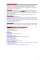
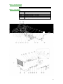
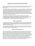
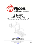
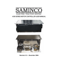
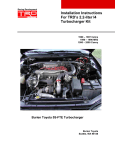
2008
2
This kit is identical to the famous kits we produced in the 80's and 90's, which,
when fitted to the new Capri's would make 200bhp.
Producing power at high speed is relatively easy, but the aim of the development
programme was to build an engine which would also produce a high level of torque
from very low speed. The key to achieving this is the exhaust manifold and Turbo
Technics design expertise has produced a technically advanced pulse separation
configuration, using a single turbo. In conjunction with the carefully matched Garrett
T3 turbocharger, excellent low speed response is achieved, with minimal turbo lag.
The resulting engine not only gives exhilarating performance, but does so in a totally
fuss-free manner, with no perceptible transition to "boost" conditions. Economy is
virtually unaffected, and an effective intercooler in conjunction with a carefully
integrated system ensures a very high degree of reliability, for which Turbo Technics
have established a trend-setting reputation.
The kit uses the standard compression ratio and runs with standard transmission and
consists of a T3 turbocharger, manifold, intercooler, vacuum capsule, fuel
enrichment air cone block, oil feed and return pipes, cross pipe and a down pipe from
the turbo as well as all the pipe work and clips to plumb everything in. The only part
not included from the original kit is the complete exhaust system - see figure 13 in
drawings.
The Turbo system can be fitted in a few days by any competent DIY-er and does not
need to be carried out by specialists. However, it is important that the engine is in
good mechanical condition before the kit is installed, especially if it has covered highmileage.
Engine Power Output.
Maximum power = 200BHP (149Kw) @ 5,500rpm
Maximum torque = 247 Lbf-Ft (320Nm) @ 3,800rpm
Typical Performance Figures
Capri
0-60 MPH
0-100 MPH
Max speed
200BHP
6.5 seconds
14.8 seconds
143 MPH on the standard final drive
The cost of the kit is £2500 + VAT. Your order will be taken with a 20% deposit.
3
CAPRI 2.8i TURBO
Service Bulletin
INTRODUCTION
The special edition Capri 2.8i Turbo follows the same turbo system layout as employed
previously by Turbo Technics on this model, and is similar to that used on the XR4i, XR4x4
and Granada models.
The turbo system is based on the use of a single Garrett AiResearch T3 turbocharger
mounted on the left side, with an air/air intercooler cooling the charge air prior to entering the
engine. The basic engine remains standard.
Harder suspension location bushes are employed at key points, together with upgraded front
brake pads. 4-pot front callipers and ventilated discs are available as an optional extra.
MODELS COVERED
Turbo system types: F9 - Turbo Technics 200 BHP (service details identical to f26)
ROUTINE SERVICING
Service intervals - 6,000 miles or 6 months.
12.000 mile (or 12 month) service -as Ford requirements, plus blow off the exterior of the
intercooler with an air line. Check all pipes for tightness.
6.000 mile (or 6 months) service -as Ford requirements, plus change spark plugs.
SPARK PLUG TYPE
NGK - BCP6ES, gap 0.75mm.
IGNITION TIMING
12° B.T.D.C @ 900 rpm -vacuum disconnected.
NOTE: On no account should the engine be run under load with the vacuum pipe
disconnected.
IDLE CO SETTING
1- 1.5% with the engine thoroughly warmed. Idle speed 900 rpm
ENGINE OIL
The use of synthetic or semi-synthetic oil is recommended for turbocharged engines Turbo
Technics approves the use of Shell Gemini in the Capri Turbo.
FURTHER SERVICE NOTES
ENGINE
F9. The engine is unmodified except for the distributor advance capsule.
TURBOCHARGER
No servicing is required for the turbocharger. In the event of a turbocharger failure, it must be
removed complete and replaced by a factory reconditioned unit. Only the pressure-controlling
wastegate actuator can be replaced as a service item... Do not attempt to dismantle the
turbocharger as this will almost certainly cause damage.
BOOST PRESSURE CHECK
Connect a suitable pressure gauge to the Inlet plenum at the multi-connection offtake. Run
the vehicle on the road in 3rd gear at 3,000 rev/min using full throttle. Hold steady speed for a
few seconds by braking with the left foot, and read the boost pressure. Repeat at 1,750
rev./min.
Pressures should be:
1,750 rpm: 3,000 rpm:
F9 0.25 bars (3.6 lbf/in2) min 0.40/0.45 bars (5.8/6.5 lbf/in2)
4
ACTUATOR REPLACEMENT
Check the actuator for free movement and diaphragm integrity by pressurising up to but not
beyond the working pressure. There should be no leakage. To replace an actuator, fit the new
unit and adjust the screwed rod-end so that it must be pulled out approximately 2mm to fit
over the pin on the arm. Road test, as described above, and adjust the pressure as
necessary; shorten the rod (1 turn at a time maximum) to increase boost, and lengthen to
reduce. Lock the nut, and refit the E-clip.
FUEL SYSTEM
The fuel system is standard, except that a profile block is fitted to the air metering cone.
However, the system is balanced to give matched flows from each injector. Injectors must
always be kept in their respective positions, and if any component of the system is changed a
flow check must be made.
With the air flap at full lift, the flow from each injector must be within 200/220 c.c./min.
IGNITION SYSTEM
The ignition system is standard except:
1. A vacuum advance/pressure retard capsule is fitted to the distributor. Retard should be
8/10° C.A. at 0.40 bars pressure at all speeds. Free movement of the base-plate should be
checked.
2. An over-boost pressure switch is fitted in the inlet plenum to interrupt the ignition feed in the
event of turbocharger control system failure.
3. Silicone ignition leads are fitted.
EXHAUST SYSTEM
The standard exhaust system is retained for the main run, including the two main expansion
boxes, cut 520mm in front of these boxes, and a 2-section front pipe and Y-piece connects.
FAULT DIAGNOSIS - SYMPTOMS AND POSSIBLE CAUSE
LOW POWER
1.0 Check vehicle servicing:
Particularly check spark plugs, filters, valve clearances
2.0 Check boost pressure:
2.1 Low pressure at 1,750 rpm:
air leak
exhaust leak
intake blockage
throttle not opening weak mixture on load
damaged turbo
turbo wastegate not closing
2.2 Correct pressure at 1,750 rpm, but low pressure at 3,000 rpm:
wastegate actuator incorrectly set
3.0 Check ignition timing:
With vacuum disconnected:
Idle timing should be 12° B.T.D.C
Timing at 3,000 rpm should be 17/21° B.T.D.C.
4.0 Check fuel/air mixture:
Check injector flows as above
Check full-throttle CO on a rolling road -should be 3 - 5% between 3,000 rpm and 5,000 rpm
5.0 Check engine condition:
Normal condition check as described in the Ford service manual.
5
MISFIRING
1.0 Check vehicle servicing:
Check spark plugs - type and condition Check H.T leads -continuity and insulation Check H.T
firing voltages
2.0 Check turbo boost at 3,000 rpm:
Over-boosting will cause intermittent cutting of the ignition supply.
DETONATION
1.0 Check fuel:
96 RON octane (4 star) minimum - NO LUBRICATING ADDITIVES
2.0 Check ignition timing:
With vacuum disconnected:
Idle timing should be 12° B.T.D.C.
Timing at 3,000 rpm should be 17/21° B.T.D.C.
Check for smooth advance action
3.0 Check ignition timing retard:
0.40 bars pressure on the distributor capsule should give 8/10° C.A. retard,
Check for smooth action
4.0 Check for over-boosting:
Boost pressure at 3,000 rpm too high
incorrect actuator setting
leaking actuator pressure pipe
perforated actuator diaphragm
sticking wastegate
5.0 Incorrect valve function:
Check valve seat condition
Check valve clearances.
Check cam timing
6.0 Oil pull-over:
Check compressor inlet and rocker cover vents for excessive oil flow
HIGH FUEL CONSUMPTION
1.0 Check part throttle CO:
CO at high idle (2,000- 3,000 rpm) should drop to below 0.50%. This with the vehicle
stationary.
On rolling road test, steady CO readings should be less than 1% at off-boost conditions.
2.0 Check ignition timing:
Particularly check the function of the vacuum advance capsule.
3.0 Check engine conditions:
HIGH OIL CONSUMPTION
1.0 Oil smoke on full power: excessive ring wear damaged pistons damaged bores
2.0 Oil smoke on over-run: poor valve guide condition damaged stem seals.
3.0 Oil smoke at idle: damaged turbo seals
4.0 engine oil leaks: damaged pistons/bores blocked breather.
6
Parts List
Item
1
2
3
4
5
6
7
8
9
10
11
12
13
14
15
16
17
18
19
20
21
22
23
24
25
26
27
28
29
30
31
32
33
34
35
36
37
38
39
40
41
42
43
44
45
46
47
47
48
49
50
51
52
Part No
TT076
1892-50
1250-51
S5025-1
S5025-1
BM1030S
S5006
NM10SP
1286-1
1286-2
1271
1272
1043-12
NM08PH
6063
1756
1763
SGL 50-70
SGL 50-70
1601-100
1764
6056
SGL 50-70
1261
6055
SGL 60-80
1191-1
1579-360
6028
1290
1221-3
S5024
PWM10C
S5034-1
6047
DW002
S5022-2
1277-0
1905
1276
6010
SGL 20-32
BM0825
SWM08
1906-2
6060
1297
DHB 224
DHB 220
DHB 216
DHB 316
1366
Description
Turbocharger assembly
Compressor inlet assembly
Exhaust manifold assembly
Stud
Stud
Bolt
Nut
Nut
Exhaust cross-pipe - left bank
Exhaust cross-pipe - right bank
Clamp flange - Ford original part
Exhaust front pipe
Exhaust centre pipe – NOT SUPPLIED IN KIT
Exhaust clamp flange
Locking nut - high temperature
U-clamp
Intercooler assembly
Air pipe - turbo to front panel
Hose clip
Hose clip
Bulkhead connection
Pipe - front panel to intercooler
Convoluted hose connection
Hose clip
Pipe - air inlet
Elbow – rubber
Hose clip
Pipe - air meter outlet
Convoluted hose
Over-boost switch
Heat shield - plug lead
Oil feed pipe
Banjo adapter
Washer – copper
Banjo
Adapter
Washer – Dowty
Banjo bolt
Oil drain pipe
Oil drain connection
Oil drain stub
Hose – silicon
Hose clip
Bolt
Washer
Breather diverter valve
One way valve
Restrictor
Ignition lead
Ignition lead
Ignition lead
Coil lead
Vacuum capsule
service
as pair
7
Brakes - Standard Calliper
6244
Brake pads Mintex
Brakes - 4 Pot Calliper
6243
6209
6206
6207
6208
1907
Brake pad
Brake disc
Calliper assembly – left side
Calliper assembly – right side
Spacer washer (2 per side)
Brake pipe
8
9
Breather System Diagram
Breather System operation
On Boost
Valve 6060 closes. Engine breathes via valve A053 to air metering unit and hence to engine.
On Over-Run
Valve A053 closes. Engine breathes via by pass, through valve 6060 to plenum chamber.
Note: 3/8" hose from plenum chamber to valve 6060 must be secured with clips. Valve A053
is tie-wrapped to the brake pipes on the bulkhead.
Detailed below are the Miofiltre Valve and Fuel Enrichment (Profile) Block
10
CAPRI V6 2.8i TURBO
The exclusive performance system developed by Turbo Technics
From the same stable as the well-renowned XR3i, the V6 turbo system employs the same
design principles, and engineering expertise to produce a superbly balanced performance.
Producing power at high speed is relatively easy, but the aim of the development programme
was to build an engine which would also produce a high level of torque from very low speed.
The key to achieving this is the exhaust manifold, and Turbo Technics design expertise has
produced a technically advanced pulse separation configuration, using a single turbo. In
conjunction with the carefully matched Garrett T3 turbocharger, excellent low speed response
is achieved, with minimum "turbo lag".
The resulting engine not only gives an already good vehicle exhilarating performance, but
does so in a totally fuss-free manner, with no perceptible transition to "boost" conditions.
Economy is virtually unaffected, and intercooling coupled with a carefully integrated system
ensures a very high degree of reliability, for which Turbo Technics have established a
trendsetting reputation.
The 200 bhp turbo engine uses standard compression ratio, and runs with standard
transmission. The turbo system can be fitted in a few days at either Turbo Technics
Northampton or Aldershot facilities, and whilst careful servicing is required, this does not need
to be carried out by specialists.
Warranty for a period of 12 months an all Turbo Technics components is included.
Engine Power Output
Typical Performance Figures
Maximum Power
0 - 60 mph ~ 6.5 seconds
200 bhp (149Kw) @ 5,500 rpm
0 - 100 mph ~ 14.8 seconds
Maximum Torque
Maximum Speed ~ 143 mph
247lbs-ft (320Nm) @ 3,800 rpm
Technical Specifications
Turbocharger
•
Turbo Technics assembled Garrett T3 with integral wastegate pressure control. The
turbo is mounted on the nearside with a link pipe carrying gas across from the off-side
manifold.
Exhaust Manifold
•
Multi-branch manifold designed for pulse separation, cast in high nickel iron.
Air Supply
•
Air supply is through the standard filter to the compressor, then cooled by a front
mounted intercooler before passing to the standard inlet manifold.
Fuel System
•
The standard injection system is retained with minor modification.
11
Ignition
•
The standard high energy electronic ignition is retained, with a modified characteristic
incorporating a vacuum advance / pressure retard capsule. Wide heat-range spark
plugs are employed, with silicone high tension leads.
Lubrication
•
An oil supply is taken from the main engine feed via Aeroquip pipe to the turbo,
returning to the sump.
Cooling
•
The standard radiator is retained.
Service
•
Apart from different spark plugs and ignition timing, servicing is unaltered.
12