1
G1
STEERING COLUMN-----------------REMOVAL AND INSTALLATION-STEERING COLUMN(INTERMEDIATE
SHAFT) ------------------------------REMOVAL AND INSTALLATION--
STEERING
G11
G11
G17
G17
G1-1
1 STEERING COLUMN
1-1 REMOVAL AND INSTALLATION
CAUTION
Refer to the OPERATING INSTRUCTIONS.
Refer to Page A1-41.
1-1-1 ARTICLES TO BE PREPARED
Tool
Drill,Tap
1-1-2 OPERATION BEFORE REMOVAL
1. Set the IG SW to "LOCK", disconnect the negative terminal of the battery and wait for at least 90
seconds.
2. Remove the steering wheel pad Ay.
Refer to TERIOS SERVICE MANUAL
3. Remove the steering wheel Ay.
Refer to TERIOS SERVICE MANUAL
4. Remove the instrument panel finish lower panel S/A.
Refer to TERIOS SERVICE MANUAL
5. Remove the No.1 instrument panel under cover.
Refer to TERIOS SERVICE MANUAL
6. Remove the instrument cluster finish panel S/A.
Refer to TERIOS SERVICE MANUAL
G1-2
1-1-3 REMOVAL AND INSTALLATION PROCEDURES
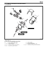
(1) Components
~g
c
h
b
e
S
f
a
S
i
S
d
B
N
T:22.6&4.9 {230&49}
T:22.6&4.9 {230&49}
~B
T:29.4&4.9 {300&49}
J13C5024S33
: Non-reusable parts
Unit: Nm{kgfcm}
(2) Removal and installation procedures
1
2
3
4
5
a
b
c
d
e
Cover, steering column, LWR
Cover, steering column, UPR
Cable S/A, spiral
Column Ay, electric power steering
Cylinder Ay, ignition SW lock
6
7
8
9
f
g
h
i
SW Ay, ignition
Bolt, steering lock set
Housing, steering column, UPR
Bracket Ay, steering column UPR W/SW
G1-3
1-1-4 POINTS OF REMOVAL
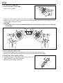
(1) Cover, steering column, LWR
1. Remove the 3 screws.
S
S
M31C7010T10
2. Press the center portion (above the claw) of the upper steering column cover in the direction indicated by the arrow so that it will not move. In the meantime, release the lower steering column
cover's claw to remove the cover.
CAUTION
If the lower cover is removed without holding the upper cover, the upper cover's claw may
be damaged.
LH
RH
J13C5001S16
(2) Cover, steering column, UPR
1. Unlock the tilt mechanism's operating lever. Fully lower the steering column Ay.
2. Remove the upper steering column cover, and then lock the operating lever again.
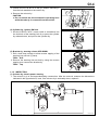
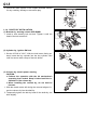
(3) Column Ay, electric power steering
1. Put match marks on the fitting section of the column Ay
and the shaft Ay, and remove the bolts.
2. Disconnect the harness connectors.
J13C5002T10
G1-4
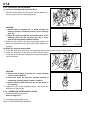
3. Loosen the nut as far as it will go, without removing it
from the bolt attached to the column Ay.
4. Remove the column Ay.
CAUTION
Do not unlock the tilt mechanism's operating lever
while the tube Ay is removed from the vehicle.
J12C5555ET10
(4) Cylinder Ay, ignition SW lock
1. Set the IG SW to "ACC", insert a stick or screwdriver into
the lock hole of the steering lock Ay to press the cylinder
Ay release button, and pull out the cylinder Ay.
J13C5003T10
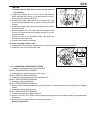
(5) Bracket Ay, steering column UPR W/SW
1. Drill a hole deep enough to allow reverse tapping of the
steering lock set bolt (1 place).
TOOL: Drill
2. Remove the steering lock set bolt by using the reverse
tapping, then remove the bracket Ay.
TOOL: Tap
J13C5004T10
1-1-5 INSPECTION
(1) Column Ay, electric power steering
1. The column Ay is of an impact-absorbing construction. After the removal, measure the dimensions
indicated in the figure below and, if the column Ay is noticeably short, replace it.
A
J13C5005S16
SPECIFIED VALUE: 435.7 mm
G1-5
2. Check the resin capsule of the impact absorber section
for any cracking, damage or excessive play.
J13C5006T10
1-1-6 POINTS OF INSTALLATION
(1) Bracket Ay, steering column UPR W/SW
1. Install a new steering lock set bolt. Tighten it until the
head of the bolt comes off.
J13C5007T10
(2) Cylinder Ay, ignition SW lock
1. Set the IG SW to "ACC". With the lock button facing upward, insert the key cylinder into the key cylinder case
until it is secure with a snap of the lock button.
J13C5008T10
(3) Column Ay, electric power steering
CAUTION
Perform the operation with the tilt mechanism's
operating lever locked. Keep it locked until the installation of the column Ay.
When installing the column Ay, do not hold its
harness.
1. With the match marks left during the removal aligned, insert the column Ay into the shaft Ay.
2. Temporarily tighten the bolt by hand till the shaft Ay can
slide slightly.
J13C5002T10
G1-6
CAUTION
Ensure that the bolt does not run on the notch of
the shaft Ay.
3. Temporarily tighten the nut of the lower side bracket,
which attaches the column Ay, to the stud bolt of the instrument panel reinforcement S/A.
4. Suspend the lower side bracket of the column Ay from
the temporarily tightened nut, in order to hold the bracket
in place.
5. Temporarily tighten the upper side bracket of the column
Ay with the bolts.
6. Securely tighten the nut on the lower side bracket of the
column Ay, and then securely tighten the bolt on the upper side bracket.
7. Tighten the bolt to the specified torque, and install the
shaft Ay into the column Ay.
8. Connect the harness connectors.
(4) Cover, steering column, UPR
1. Unlock the tilt mechanism's operating lever, and then fully lower the steering column Ay.
2. Install the cover to it by fitting the claw.
J12C5555ET10
J12C5556ET10
1-1-7 OPERATION AFTER INSTALLATION
1. Install the instrument cluster finish panel S/A.
Refer to TERIOS SERVICE MANUAL
2. Install the No.1 instrument panel under cover.
Refer to TERIOS SERVICE MANUAL
3. Install the instrument panel finish lower panel S/A.
Refer to TERIOS SERVICE MANUAL
4. Install the steering wheel S/A.
Refer to TERIOS SERVICE MANUAL
5. Ensure that the steering wheel S/A and the tires are in a position where the vehicle will move straight
ahead.
6. Install the steering wheel pad Ay.
Refer to TERIOS SERVICE MANUAL
7. Connect the battery's negative terminal.
8. Set the IG SW to "ON". Ensure that the airbag warning lamp turns off after lighting for approximately
6 seconds.
9. Perform the zero-point correction of the torque sensor.
Refer to Page G2-33.
G1-7
2 STEERING COLUMN(INTERMEDIATE SHAFT)
2-1 REMOVAL AND INSTALLATION
2-1-1 OPERATION BEFORE REMOVAL
1. Remove the engine under cover.
Refer to TERIOS SERVICE MANUAL
2. Remove the steering column Ay.
Refer to Page G1-1.
2-1-2 REMOVAL AND INSTALLATION PROCEDURES
(1) Components
~B T:29.4&4.9 {300&49}
a
~B T:29.4&4.9 {300&49}
b
~B T:35.0&5.6 {357&57}
J13C5009S33
: Non-reusable parts
Unit: Nm{kgfcm}
(2) Removal and installation procedures
1
2
a Shaft Ay, steering intermediate
b Joint Ay, steering shaft universal, No.2
G1-8
2-1-3 POINTS OF REMOVAL
(1) Shaft Ay, steering intermediate
1. Put match marks on the fitting section between the joint
Ay and the shaft Ay, and remove the bolts.
J13C5010T10
(2) Joint Ay, steering shaft universal, No.2
1. Put match marks on the fitting section between the steering gear Ay and the joint Ay, and remove the bolts.
J13C5011T10
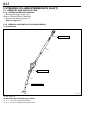
2-1-4 INSPECTION
(1) Shaft Ay, steering intermediate
1. The shaft Ay is of an impact-absorbing construction. After the removal, measure the dimensions indicated in the figure below and, if the joint Ay is noticeably short, replace it.
A
J13C5012S16
SPECIFIED VALUE: 405 mm
G1-9
2-1-5 POINTS OF INSTALLATION
(1) Joint Ay, steering shaft universal, No.2
1. With the match marks left during the removal aligned, insert the joint Ay into the steering gear Ay.
J13C5011T10
CAUTION
Ensure that no grease etc. is stuck around the
steering pinion's serrated section of the steering
gear Ay.
Insert the joint Ay until the serrated section of the
steering pinion of the steering gear Ay is completed insertely (Until it makes contact).
2. Install the joint Ay into the gear Ay,steering, tighten the
bolt to the specified torque after temporarily tightening it
by hand.
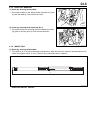
(2) Shaft Ay, steering intermediate
1. Insert the shaft Ay into the hole of the steering column hole shield from the vehicle interior.
2. Insert the shaft Ay into the joint Ay after with the match
marks left during the removal aligned, temporarily tighten
the bolt by hand.
J13C5033T10
J13C5010T10
CAUTION
Ensure that no there is grease etc. on the serrated
section of the shaft Ay.
Insert the shaft Ay until the serrated section is
completely inserted (Until it makes contact).
Ensure that the bolt does not run on the notch of
the shaft Ay.
3. Tighten the bolt to the specified torque, and install the
shaft Ay into the joint Ay.
2-1-6 OPERATION AFTER INSTALLATION
1. Install the steering column Ay.
Refer to Page G1-1.
2. Install the engine under cover.
Refer to TERIOS SERVICE MANUAL
J13C5034T10