1
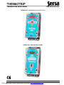
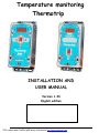
Temperature monitoring
Thermotrip
INSTALLATION AND
USER MANUAL
Version 1.24
English edition
PDF created with FinePrint pdfFactory trial version http://www.fineprint.com
THERMOTRIP
TEMPERATURE MONITORING
SSA 202001X & B
THERMOTRIP SSA202001X for four-wheel drive
THERMOTRIP SSA202001B for BUGGY
202099-2
PDF created with FinePrint pdfFactory trial version http://www.fineprint.com
Page2 of 16
THERMOTRIP
TEMPERATURE MONITORING
SSA 202001X & B
CONTENTS
1
PRESENTATION..............................................................................................................................................................................................................4
Adjustment keys .....................................................................................................................................................................................................5
Display ....................................................................................................................................................................................................................5
Presentation of the mimic-diagram panels .............................................................................................................................................................5
EQUIPMENTS SUPPLIED...............................................................................................................................................................................................6
INSTALLATION ................................................................................................................................................................................................................8
3.1
Preparation .............................................................................................................................................................................................................8
3.2
Wiring of the sensors ..............................................................................................................................................................................................8
3.3
Allocation of channels SSA202001X ( 4-WHEEL DRIVE VERSION) ....................................................................................................................9
3.4
Allocation of channels SSA202001B (BUGGY VERSION) ..................................................................................................................................10
3.5
Power supply wiring..............................................................................................................................................................................................11
3.6
Alarm Output Wiring .............................................................................................................................................................................................11
CONFIGURATION .........................................................................................................................................................................................................12
4.1
Modification alarm temperature thresholds ..........................................................................................................................................................12
OPERATION ..................................................................................................................................................................................................................12
5.1
Alarms and faults ..................................................................................................................................................................................................12
5.2
Maximum temperatures reached..........................................................................................................................................................................12
CONFIGURATION by WinMonitor................................................................................................................................................................................13
6.1
Installation of WinMonitor....................................................................................................................................................................................13
CHARACTERISTICS......................................................................................................................................................................................................16
7.1
Inputs / outputs .....................................................................................................................................................................................................16
7.2
Accuracy ...............................................................................................................................................................................................................16
7.3
Display ..................................................................................................................................................................................................................16
7.4
Case......................................................................................................................................................................................................................16
ENVIRONMENT .............................................................................................................................................................................................................16
ORDER CODES.............................................................................................................................................................................................................16
1.1
1.2
1.3
2
3
4
5
6
7
8
9
202099-2
PDF created with FinePrint pdfFactory trial version http://www.fineprint.com
Page3 of 16
THERMOTRIP
TEMPERATURE MONITORING
1
SSA 202001X & B
PRESENTATION
Two types of THERMOTRIP are available:
q Version 202001X for four-wheel drive vehicle.
q Version 202001B for Buggy.
The THERMOTRIP takes the form of an independent case grouping together the functions of:
• Measurement of water temperatures engine and radiator.
• Measurement of oil temperature engine, gearbox and transfer.
• Measurement of exhaust temperature.
• Measurement axles temperature.
• Measurement of shock-absorber temperature.
• display of temperatures and alarms.
• Programming of temperature alarm threshold.
• Recording and reading of temperature maxima.
• Dialogue with a PC for configuration and reading of maxima.
The mimic-diagram type front panel makes reading of the various points of measurement easier. It incorporates two independent displays:
one to indicate the temperature of the selected input, the other to indicate the number of the cylinder selected. The selection of the other
inputs is indicated by an orange-coloured indicator lamp placed at the various points of the mimic diagram. Four keys enable the selection
of the input which is to be displayed and the setting of the operating parameters of the THERMOTRIP.
The 202001X has 24 inputs for type K thermocouples, divided into 2 groups:
• 16 inputs with a temperature range from 50°C to 250°C.
• 8 inputs with a temperature range from 50°C to 1000°C (exhausts).
The 202001B has 22 inputs for type K thermocouples, divided into 2 groups:
• 14 inputs with a temperature range from 50°C to 250°C..
• 8 inputs with a temperature range from 50°C to 1000°C (exhausts).
The 50-1000°C sensors are to be ordered separately ( see 9
ORDER CODES)
Each measurement is associated with a set-point value between 50 and 250°C (or 50 and 1000°C, depending on the input concerned).
The number of inputs used and the associated set point values are programmable by an external PC via the serial link, or directly by the
keys on the front panel.
The measurement inputs and the power supply are connected to the rear panel of the module.
Pull-out tension clamp connectors allow each input to be individually connected to its sensor via the compensated cable supplied. The
other end of the cable is fitted with a compensated connector (female) for connection to the sensor.
202099-2
PDF created with FinePrint pdfFactory trial version http://www.fineprint.com
Page4 of 16
THERMOTRIP
TEMPERATURE MONITORING
1.1
SSA 202001X & B
Adjustment keys
A brightness adjustment key allows access to four display modes:
1. No display (except in case of alarm: high brightness display)
2. Low brightness display (night time)
3. Medium brightness display (normal)
4. High brightness display (in full sunshine)
Two up and down keys enable:
1. Scrolling of the measurement inputs
2. To increase or decrease the alarm threshold value of temperature in mode PROGRAMMING ( see 4
CONFIGURATION ).
The programming key allows access to the alarm temperature threshold-setting menu.
This key also allows the recorded maximum temperatures to be read and erased.
1.2
Display
Two displays are used to display the value of temperature:
and the number of the cylinder selected:
The other measurement inputs are associated with an orange-coloured indicator lamp positioned on the components of the vehicle.
1.3
Presentation of the mimic-diagram panels
4 adjustment /
programming
keys
Display of
temperatures
Display of
cylinder number
(1 to 8)
Indicators lamps
allotted to inputs
(each white patch)
Alarm
indicators
Version 4x4
Version Buggy
Connector for
connection to PC
202099-2
PDF created with FinePrint pdfFactory trial version http://www.fineprint.com
Page5 of 16
THERMOTRIP
TEMPERATURE MONITORING
2
SSA 202001X & B
EQUIPMENTS SUPPLIED
All elements necessary for installation of the THERMOTRIP on the vehicle are contained in the valise. In it can be found:
Ø
The THERMOTRIP case
Ø
10 measurement sensors:
- 8 sensors (250°C) for gluing; length 90cm. Reference : 202002
-
2 thimble sensors ∅8mm (250°C) ; length 90cm. Reference : 202003
Each sensor is equipped with a compensated connector with locating pin enabling the whole thing to be disconnected quickly.
Ø
10 compensated connectors for thermocouple (female). Reference : 202004
Ø
1 reel of 25m of compensated cable for thermocouple K. Reference : 202006
202099-2
PDF created with FinePrint pdfFactory trial version http://www.fineprint.com
Page6 of 16
THERMOTRIP
TEMPERATURE MONITORING
SSA 202001X & B
Ø
10 - 2-pin pull-out connectors (sensor inputs). Reference : 202005
Ø
1 – 3-pin pull-out connector (power supply).
Ø
Screwdriver for insertion/extraction of the cables in the pull-out tension clamp connectors. Reference : 202007
Ø
One serial link cable (circular connector à 9 pin SUBD connector); length 2m. Reference : 202008
Ø
“WinMonitor” configuration / monitoring software for pour Windows 9X, 2000, Me, XP or NT4.x. Reference : 202009
Ø
The present instructions in English. Reference : 202099-2
OPTION
-
4 sensors (1000°C) to fix on the exhausts; length of sensor 30cm; length of cable 1.5m. Reference : 202011
Connection
Compensated
connectors
Exhaust
Sensor
Compensation
cable
Collars
THERMOTRIP end
High-temperature collars
202099-2
PDF created with FinePrint pdfFactory trial version http://www.fineprint.com
Page7 of 16
THERMOTRIP
TEMPERATURE MONITORING
3
SSA 202001X & B
INSTALLATION
3.1
Preparation
The first stage of the installation consists in defining the place where the THERMOTRIP will be fixed. For preference choose a place which
is protected from dust, from water and from very large variations of light. The fixation of the monitor must be by at least three fixation
points.
The second stage consists in passing through sufficient compensation cable for the number of sensors to be connected. For this purpose,
use the reel of cable supplied with the equipment.
Use only the compensation cable supplied with the outfit. to avoid wear on the cables, it is preferable t cover them with a protective
sheath.
Since the power supply is polarized, a cable with two wires of different colours is strongly recommended.
3.2
Wiring of the sensors
CAUTION: The compensation cable is a POLARISED CABLE, it is therefore necessary to observe the polarities of connection as follows:
Watertight seal
Polarity of connectors and cable
Green (+)
White (-)
5mm
15mm
Direction of winding the
wires around the screws
Screwed
cover
Positive terminal
White (-)
Green (+)
Compensated connectors
Compensation cable
Pull-out connector
Once the compensated cable are installed in the vehicle, it remains only to install a compensated connector (sensor end) and a pull-out
connector (THERMOTRIP end), observing the indicated polarities. After this connect each cable to the THERMOTRIP observing the
input number allotted to each sensor. The insertion tool supplied will be used to connect the wires of the compensated cable to the pull-out
connector. For this purposes, strip the wires without damaging them, insert the blade of the screwdriver into the upper slot of the connector
(see figure below), then exert a slight pressure on the connector clamp and insert the corresponding wire into it. Release the pressure on
the clamp while holding the wire in position. Pull gently on the wire to ensure that it is properly gripped in the clamp. Repeat the procedure
for the second wire of the compensation cable.
Connection
Compensated
connectors
Compensation
cable
Collars
THERMOTRIP end
Sensor
High-temperature adhesive
Component to be monitored
Remove the connector mask situated on the back of the THERMOTRIP.
Then connect each sensor to the THERMOTRIP observing the input number allocated to each sensor (indication on the bottom panel of
the device). The figures on the following page summarize the allocation of each measurement channel with respect to its input connector.
202099-2
PDF created with FinePrint pdfFactory trial version http://www.fineprint.com
Page8 of 16
THERMOTRIP
TEMPERATURE MONITORING
3.3
SSA 202001X & B
Allocation of channels SSA202001X ( 4-WHEEL DRIVE VERSION)
E24
E23
+12V Alarm 0V
E12
E11
E13
E22
E14
E1 à 8
E20
E21
E19
E18
E10
E15
E9
Input N°
E1 to E8
E9
E10
E11
E12
E13
Allocation
Exhausts 1 to 8
Sh. absorber Rear Left Lwr
Sh. absorber Rear Left Upr
Sh. absorber Front Left Lwr
Sh. absorber Front Left Upr
Sh. absorber Front Right Upr
Input N°
E14
E15
E16
E17
E18
E19
Allocation
Sh. absorber Front Right Lwr
Sh. absorber Rear Right Upr
Sh. absorber Rear Right Lwr
Rear axle
Transfer box
Gearbox
E17
Input N°
E20
E21
E22
E23
E24
202099-2
PDF created with FinePrint pdfFactory trial version http://www.fineprint.com
E16
Allocation
Engine oil
Engine water
Front axle
Radiator water
Option
Page9 of 16
THERMOTRIP
TEMPERATURE MONITORING
3.4
SSA 202001X & B
Allocation of channels SSA202001B (BUGGY VERSION)
E21
E20
E12
E11
+12V Alarm 0V
E13
E14
E19
E1 à 8
E18
E10
E9
Input N°
E1 to E8
E9
E10
E11
E12
E13
Allocation
Exhausts 1 to 8
Sh. absorber Rear Left Lower
Sh. absorber Rear Left Upper
Sh. absorber Front Left Lower
Sh. absorber Front Left Upper
Sh. absorber Front right Upper
Input N°
E14
E15
E16
E17
E18
E19
Allocation
Sh. absorber Front right Lower
Sh. absorber Rear right Upper
Sh. absorber Rear right Lower
Rear axle/ Gearbox
Engine oil
Engine water
E15
E16
E17
Input N°
E20
E21
E22
E23
E24
202099-2
PDF created with FinePrint pdfFactory trial version http://www.fineprint.com
Allocation
Radiator water
Option
Unused
Unused
Unused
Page10 of 16
THERMOTRIP
TEMPERATURE MONITORING
SSA 202001X & B
3.5
Power supply wiring
Start by connecting the power supply of the module, observing the polarities (a cable made up of different coloured wires is preferable). The
THERMOTRIP is not equipped with an on/off switch. Even if the display is not in operation, the system continues to operate with reduced consumption,
we therefore recommend that you should connect the 12 V supply of the system to a +12V after contact )(+Neiman) or to a circuit-breaker dedicated to
electronic apparatus.
If the power supply is no longer present on the THERMOTRIP, the configuration parameters and the maxima are retained in non-volatile memory.
As soon as the power supply is connected, all the indicator lamps light for 3 to 4 seconds to check correct operation. Then carry on with the configuration
of each input (see chapter 4 CONFIGURATION).
3.6
Alarm Output Wiring
The Alarm Output is used to supply large variety of equipment for which the consumption doesn’t exceed 2 Amps at 12Vdc (24 Watts).
If the power of the equipment to be supplied exceeds 2 Amps, an additional relay is necessary (see wiring with additional relay section) .
In case of short circuit, the Alarm output is self protected with auto-reset function.
Direct wiring (equipment < 24W max) :
Power Supply Connector
+12V +Alarm 0V
Cable section must be ≥ 0,75mm²
Equipment < 21W
+
Battery
Wiring with additional relay ( equipment >24W) :
Relay
+
Equipment >21W
-
Battery
202099-2
PDF created with FinePrint pdfFactory trial version http://www.fineprint.com
Page11 of 16
THERMOTRIP
TEMPERATURE MONITORING
4
SSA 202001X & B
CONFIGURATION
4.1
Modification alarm temperature thresholds
The modifications of set points are carried out directly by means of the front panel keys of the THERMOTRIP , or via the “WinMonitor” software supplied
(refer to chapter 6 CONFIGURATION by WinMonitor).
With the THERMOTRIP under power, select the channel to be modified using the up-down keys, then press the key Prg (Programming).
The indicator corresponding to the previously displayed input flashes. The temperature displayed now corresponds to the value of alarm threshold above
which an alarm will be displayed.
Use the up and down keys to scroll to the temperature value which you wish to allocate to this input. The maximum value programmable for an exhaust
measurement input is 1000°C ; and 250°C for the other inputs. The minimum value of the threshold is 50°C.
If the value 50 has been reached and if the down key is pressed once more, the display indicates OFF. In this case, the selected input (orange indicator
flashing) is no longer programmed: this means that no measurement will be taken into account nor displayed on this input. To take account of this input
again, press the up key once or more times until 50 appears, or the threshold value that you want.
To move to the threshold value of the next input, press the programming key once..
Repeat the adjustment using the up and down keys as seen above.
To leave programming mode, it is only necessary to wait for a few seconds, then the indicator or the display of the selected input stops flashing and the
temperature display now indicates the real temperature of the input concerned.
5
OPERATION
It is possible to consult the temperatures by pressing he + or - keys. The LED of the input visualized de glows steadily.
If an exhaust temperature exceeds 1000°C, the first digit of the display is A for 1000°C, then B for 1100°C, etc.
For example :
indicates a température of 1053°C and
indicates a température of 1135°C.
5.1
Alarms and faults
When an input is on alarm (set point exceeded) :
The display moves into high brightness mode (the brightness adjustment key no longer allows the display to be totally extinguished.
The 2 “brake lights” of the mimic diagram flash.
The LED of the defective input lights.
An alarm or a fault is always indicated by the flashing of the of the temperature display
.
If the value indicated is a number, it corresponds to a temperature exceeding the alarm temperature value previously programmed.
If the display indicates
, this means a thermocouple fault (broken wire or disconnection of the thermocouple ).
CAUTION: if an input is configured (threshold value different from OFF) and no sensor is connected to this input, the input is considered to be in fault.
If second fault occurs, the faults will be automatically displayed one after the other with a pause between faults.
If an exhaust fault is indicated, the cylinder number(s) scroll on the engine display
.
5.2
Maximum temperatures reached
A long pressure on the Prg key allows access to reading the maxima. All displays and indicators flash. The key allows passage from a channel to the
following channel. A further long pressure has the effect of setting all the maxima values to 0-.
On the other hand, if no key is operated for 5 seconds in this mode, the maxima values are retained in memory.
202099-2
PDF created with FinePrint pdfFactory trial version http://www.fineprint.com
Page12 of 16
THERMOTRIP
TEMPERATURE MONITORING
6
SSA 202001X & B
CONFIGURATION by WinMonitor
Minimum configuration required to install and use the WinMonitor software:
Ø
Ø
Ø
Ø
Ø
Ø
6.1
PC PENTIUM I 166MHz minimum
16 Mo of RAM
10Mo of hard disk free
Video board 2Mo minimum
VGA screen 800x600
Windows™ 95, 98, 2000, Me, XP or NT4.X installed
Installation of WinMonitor
1.
Insert the WinMonitor CDROM.
2.
3.
Choose the directory which suits your equipment (4-wheel drive version 4x4 or Buggy version).
In the selected directory, double-click on the file SETUP.EXE.
4.
Follow the instructions of the installation software.
At the end of the installation, the directory SERSA is created by default (or the position you have chosen), containing the WinMonitor software.
Double-click on WinMonitor.exe to start the application.
The first time the software is opened a window opens which enables the software to choose the communication port used for the dialogue with the
THERMOTRIP.
202099-2
PDF created with FinePrint pdfFactory trial version http://www.fineprint.com
Page13 of 16
THERMOTRIP
TEMPERATURE MONITORING
SSA 202001X & B
The second window offers 3 choices:
1.
2.
3.
Reading and setting of set points
Retrieval of measurements
Exit from application
By clicking on the button “Set points reading and setting ” the following window is reached.
Each measurement channel is associated to a temperature value and to a tick-box indicating whether the channel is in service or not.
Fill in the various boxes corresponding to each sensor used, then click on the button “Set points Programming ” to download the values into the
THERMOTRIP memory.
202099-2
PDF created with FinePrint pdfFactory trial version http://www.fineprint.com
Page14 of 16
THERMOTRIP
TEMPERATURE MONITORING
SSA 202001X & B
Retrieval of measurements
This window resembles the previous one, except that the values displayed are those memorized in the non-volatile memory of the THERMOTRIP .
The window “Reference of the stage” is reserved for the commentary which will be recorded at the same time as the maxima data, in the file savemax.txt
(same directory as the application). To save the measurements following on from the measurements already contained in the file: click on the button
“Save measurements”.
Once this operation has been successfully carried out, it is possible to erase the maxima in memory by clicking on the button “Erase memory”.
This will make it possible to take into account new values of maxima.
202099-2
PDF created with FinePrint pdfFactory trial version http://www.fineprint.com
Page15 of 16
THERMOTRIP
TEMPERATURE MONITORING
7
7.1
•
•
•
•
7.2
SSA 202001X & B
CHARACTERISTICS
Inputs / outputs
16 Inputs thermocouple K for measurements of temperature up to 250°C .
8 Inputs thermocouple K for measurements of temperature up to 1000°C (Exhausts).
2 power supply wires 12VDC protected against inversions of polarity. Operating range: 10VDC to 16VDC.
1 RS232C connection for connection to a PC.
Accuracy
• For Inputs 50..250°C : ±1°C
• For Inputs 50..1000°C : ±4°C
• For temperatures lower than 50°C, the values displayed are given for information.
7.3
•
•
•
•
•
7.4
•
•
•
•
8
•
•
•
•
9
Display
3 – 7-segment red displays for the temperature.
1 7-segments red display for the cylinder number (1 to 8)
10 orange LED indicators to show the measurement point displayed.
2 red LED indicators to indicate that a set point has been exceeded.
1 orange LED indicator to show that a thermocouple is cut off or disconnected.
Case
Material: Cast aluminium.
Dimensions of monitor: Width 80mm, Height 150mm, Depth 75mm.
Weight: 800g.
Fixation: by 4 oblong holes 10x4mm pitches 50 and 165 mm
ENVIRONMENT
Operating temperature: -20°C to +65°C.
Humidity : 90 % RH not condensed.
Consumption on standby: < 0.1W at 14.4Vcc
Maximum consumption: < 0.4W at 14.4Vcc
ORDER CODES
Two types of version are available:
KIT 202001X for 4-wheel drive pour vehicle
KIT 202001B for Buggy.
Each containing:
2X ref.: 202002 : 4 temperature sensors for gluing (0-250°C).
1X ref.: 202003 : 2 temperature sensors with thimble (0-250°C).
2X ref.: 202004 : 5 female compensated connectors for thermocouple K.
2X ref.: 202005 : 5 pull-out connectors for sensors + 1 power supply connector.
1X ref.: 202006 : 1 reel of 25m of compensated cable for thermocouple K.
1X ref.: 202007 : 1 insertion / extraction screwdriver for pull-out connector.
1X ref.: 202008 : 1 PC connection cable 2m, supplementary.
1X ref.: 202009 : 1 WinMonitor software.
1X ref.: 202010 : 1 transport valise for the outfit.
1X ref.: 202099-2 : the present technical note.
On option :
ref.: 202011 : 1 temperature sensor (0-1000°C) for fixation to exhaust by adhesive (not supplied).
All references can be separately ordered: please contact your contact assistant for further details.
202099-2
PDF created with FinePrint pdfFactory trial version http://www.fineprint.com
Page16 of 16