1
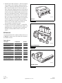
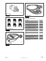
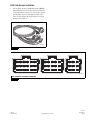
TP-1388
Issued 09-13
Technical Bulletin
Electronically Controlled Air
Suspension (ECAS) Retrofit Kit
Installation Instructions for
Meritor WABCO 6S/6M ATC Brake
Systems
Issued
1TP-1388
Technical
09-13
Bulletin
Hazard Alert Messages
ECAS Overview
Read and observe all Warning and Caution hazard alert messages in
this publication. They provide information that can help prevent
serious personal injury, damage to components, or both.
The Meritor WABCO ECAS is an electrically controlled air suspension
system designed to enhance the performance of the vehicle’s air
suspension when equipped with a Meritor WABCO 6S/6M ATC
brake system. The ECAS maintains an accurate leveling of the
chassis height through the use of height sensors, electronic control
unit (ECU) and solenoid valves. Because of the variety of suspension
types and vehicle features, a particular set of parameters was
developed for each vehicle type. These parameters determine some
of the features and characteristics for the ECAS configuration. In the
event of a malfunction in the system, the ECAS indicator lamp will
alert the driver and the suspension will retain the existing air
pressure in the air suspension bellows. Several of the features
provided by ECAS include the following.
WARNING
To prevent serious eye injury, always wear safe eye protection
when you perform vehicle maintenance or service.
Park the vehicle on a level surface. Block the wheels to
prevent the vehicle from moving. Support the vehicle with
safety stands. Do not work under a vehicle supported only by
jacks. Jacks can slip and fall over. Serious personal injury and
damage to components can result.
Release all air from the air systems before you remove any
components. Pressurized air can cause serious personal
injury. Refer to the vehicle manufacturer’s service manual for
instructions.
How to Obtain Additional Maintenance,
Service and Product Information
Refer to Maintenance Manual MM-1315, Electronically Controlled
Air Suspension (ECAS) for Buses and Trucks with CAN II (SAE 1939);
and User Guide SP-1372, Electronically Controlled Air Suspension
(ECAS) Driver Tips. If you have any questions about the material
covered in this publication, or for more information about the Meritor
WABCO product line, please contact the OnTrac Customer Service
Center at 866-OnTrac1 (668-7221) or visit our website:
meritorwabco.com
How to Obtain Parts and Kits
Contact Meritor’s Commercial Vehicle Aftermarket at
888-725-9355.
TOOLBOX™ Software
This procedure requires TOOLBOX™ Software version 11.0 or
higher. To download this software, visit meritorwabco.com.
앫 Automatic Level Control — The ECAS continually monitors the
vehicle’s height (axle-to-frame distances) through the ECU and
the use of height and pressure sensors. When the height
deviates from the preset nominal level, a correction is made
quickly, exhausting or pressurizing the air suspension bellows by
actuating solenoid valves. The ECAS will maintain the nominal
vehicle level regardless of the number of passengers boarding or
unloading. There are pre-selected restrictions for when the
height corrections can be made.
앫 Driver-Controlled Level Adjustment — Other than the nominal
vehicle level, there can be additional levels selected by the driver
to raise the vehicle for rough surfaces or lower vehicle height.
These levels can be selected by switches on the vehicle dash
panel. The driver can also return the vehicle to the nominal level
(Recovery). There are pre-selected restrictions for when the
height changes can be made.
앫 Automatic Traction Help Load Transfer — When wheel slippage
is detected by the vehicle’s ABS (due to slippery road surface
conditions), a signal from the ABS triggers the ECAS system. The
ECAS can transfer weight from the non-drive axle (tag) to the
vehicle’s drive axle by changing air pressures in the rear axles air
suspension bellows. By transferring pressure from the tag axle to
the drive axle air bellows, additional weight is transferred to the
drive axle, increasing drive wheel traction. This function may also
be initiated by the driver activating a switch on the vehicle dash
panel. There are pre-selected restrictions for when the traction
help can be activated and how much weight can be transferred.
The ECAS will continue to hold the transferred load until the
preset speed limit has been met, which is 25 mph. If the load
transfer is active, all chassis height control functions are
suspended until the load transfer has ended.
Figure 1
4010354a
ECAS ECU
Figure 1
Figure 2
앫 Inclination Level Control (Pressure Equality) — The ECAS ECU
can adjust pressures in all air suspension bellows together or in
individual air bellows. This allows the ECAS to compensate for
inclinations caused by unbalanced loads or uneven road
surfaces.
Kit Parts List
Locate and verify that the kit is complete and that you have access
to TOOLBOX™ Software version 11.0 or higher prior to beginning
the installation of this kit.
Table A: Kit Parts
Description
Part Number
Quantity
ECAS ECU
S400 850 920 0
1
ECAS Cab Harness
S400 850 916 0
1
ECAS Frame Harness
S400 850 918 0
1
ECAS Solenoid Valves
S472 880 073 0
2
Distance Sensor
S441 050 100 0
1
ECAS Sensor Lever
S441 050 718 2
1
ECAS Sensor Linkage
S433 401 003 0
1
Pressure Sensors
S441 044 106 0
2
M22 Fitting Adapters 1/2”
S400 851 002 4
6
ECAS Valve Bracket
S400 850 055 4
2
4010357a
ECAS SOLENOID VALVES
Figure 2
Figure 3
4010363a
DISTANCE SENSOR
Figure 3
TP-1388
Issued 09-13
Page 2
Copyright Meritor, Inc., 2013
(16579)
Printed in USA
Figure 4
Figure 7
4010860a
4010898a
PRESSURE SENSOR
Figure 4
ECAS CAB HARNESS
Figure 7
Figure 5
Table B: Additional Items Required
4010861a
M22 FITTING ADAPTERS 1/2”
Figure 5
Description
Quantity
Various quick connect fittings for the air lines
As needed
Street T Fittings (1/4″)
2
Valve Mounting Nuts (5/16″)
4
Valve Mounting Bolts (2-1/2-inch, 5/16″)
4
Bracket Mounting Nuts (5/8″)
4
Bracket Mounting Bolts (2-inch, 5/8″)
4
Additional Air Line
As needed
Incandescent Amber Light – DO NOT USE LED
Lights
1
Incandescent Red Light – DO NOT USE LED
Lights
1
Three-Position Momentary Switch
1
Two-Position Momentary Switch
1
J1939 Y Connector
1
J1939 Connectors
3
Figure 6
4010895a
ECAS FRAME HARNESS
Figure 6
(16579)
Printed in USA
Copyright Meritor, Inc., 2013
TP-1388
Issued 09-13
Page 3
Procedures
Leveling Valve Installation (Must Be Mounted
on the Drive Axle)
Valve and Bracket Installation
1.
Wear safe eye protection. Park the vehicle on a level surface.
Block the wheels to prevent the vehicle from moving.
2.
Lower and exhaust all air from the suspension system.
3.
Determine the valve mounting location. Verify the valve has
correct clearance from the suspension and ensure it is
positioned so the valve’s exhaust silencer is NOT pointing
upward. NOTE: The mounting brackets are not pre-drilled so
they can be used for any mounting location. Figure 8.
1.
Verify the nominal ride height and measurement location
per OEM specifications. This information will be used to
set the electronic height sensor as well as calibrate the
system.
2.
Connect the leveling valve to the drive axle of the tractor. In
most cases, the existing pneumatic air valve bracket can be
used to mount the electronic height sensor. Figure 9.
Figure 9
Figure 8
SENSOR
MOUNTING
BRACKET
SILENCER
NOTE: Brackets are not pre-drilled.
4010893a
NOTE: The sensor
must be installed
with the mounting
bolts above the
sensor housing.
Figure 8
4.
Position the brackets to the frame at the chosen mounting
location. Drill out the frame and brackets as required.
5.
Remove the existing metric fittings from the ECAS valve and
replace them with the M22 fitting adapters, part number
S400 851 002 0, provided in the kit.
6.
Install the quick connect fitting to port 11, which is the air
supply port to the valve.
7.
Install quick connect fittings to the adapters on port 22 and 23.
These ports allow the air to travel to and from the bellows.
TP-1388
Issued 09-13
Page 4
4010894a
Figure 9
3.
Connect the rod ends using a 1/4″ (6.35 mm) smooth or
threaded rod. Verify that the height sensor can reach full travel
without contacting the frame or wiring.
4.
Loosely tighten the connection. Final tightening will be made
with air in the bellows.
Copyright Meritor, Inc., 2013
(16579)
Printed in USA
Air Supply Fitting and Bellow Fittings
Installation
1.
6.
Remove the air line and fitting from both passenger side air
bags. Figure 10.
Verify the air lines for the bellows are connected to the
corresponding valve, Tag or Drive. The bellows on the Tag must
be connected to the valve designated as the Tag axle, curbside
to port 22 and street side to port 23. Figure 12.
Figure 12
Figure 10
SUPPLY
LINE
AIR
SUSPENSION
BELLOW
DRIVE
AXLE
TAG
AXLE
AIR SUPPLY
TANK
4010864a
4006870a
Figure 10
2.
Figure 12
Replace the fittings with 1/4" (6.35 mm) street T fittings.
Figure 11.
7.
Once all of the connections have been made, secure the air
lines in place.
ECAS Frame Harness Installation
Figure 11
1.
4010863a
Untie the ECAS frame harness bundle (part number
S400 850 918 0) and stretch it out on the floor. Note that one
end has a 23-pin female Deutsch connector and the other has
five separate connectors. Secure the harness by taping the
bundle every 24-30″ (610-762 mm). This will assist in routing
and securing the harness for final installation. Figure 13. For a
wiring diagram, refer to Figure 14.
Figure 13
Figure 11
3.
Once the T fittings are in place, install the pressure sensors so
they are on top of the T fittings.
Suspension Air Line Installation
1.
Locate and trace the air supply source to the suspension.
2.
Deactivate the manual air suspension dump switch.
Deactivation of the manual air suspension dump switch may be
made here or at the dash lever in the cab. Contact the
manufacturer or OEM for correct disabling procedures.
3.
Replace the air lines for the rear suspension, if necessary.
4.
Ensure the air supply line runs from the supply tank fitting to
port 11 on both valves.
5.
Make sure the air lines for the bellows are connected to the
corresponding valve, Tag or Drive. The bellows on the drive
must be connected to the valve designated as the drive axle,
curbside to port 22 and street side to port 23.
(16579)
Printed in USA
4010895a
Figure 13
Copyright Meritor, Inc., 2013
TP-1388
Issued 09-13
Page 5
Figure 14
SOLENOID VALVE
CABLE
DRIVE AXLE
2
S1
A
B
C
D
E
F
G
H
I
J
K
L
M
N
O
P
Q
R
S
T
U
V
W
X
1
3
4 SKT
SOLENOID VALVE
CABLE
TAG AXLE
2
1
DRIVE PRESSURE SENSOR/TAG PRESSURE SENSOR
DRIVE MODULATOR/TAG MODULATOR
HEIGHT SENSOR – LEFT SIDE
DRIVE PRESSURE SENSOR – LEFT
DRIVE PRESSURE SENSOR/TAG PRESSURE SENSOR/HEIGHT SENSOR
DRIVE MODULATOR
DRIVE MODULATOR
TAG MODULATOR
3
4 SKT
PRESSURE SENSOR
CABLE
DRIVE AXLE
1
2
3
4 SKT
TAG PRESSURE SENSOR-LEFT
TAG MODULATOR
PRESSURE SENSOR
CABLE
TAG AXLE
BULKHEAD
COMM.
1
3
2
1
4
3
2
4 SKT
HEIGHT SENSOR
CABLE
DRIVE AXLE
1
LOOKING INTO THE
HARNESS CONNECTOR
2
2 SKT
4010897a
ECAS FRAME WIRING DIAGRAM
Figure 14
2.
3.
Locate the entry point for the Deutsch connector at the front of
the cab. Secure the retaining nut from the pass through
connector for reuse. Note: The retaining nut is not included in
the kit. The unit may have a blank on the passenger side that
may be used or installation may require use of the existing
Deutsch connector location. This will require re-pinning of the
existing OEM connector. These pins may be installed in the
ECAS CAN II Deutsch connector as there are 13 vacant pin
outs that can be used.
Route the harness to the corresponding valve and pressure
sensor, making sure to allow for correct installation of Deutsch
connector. Verify all connections prior to securing the harness.
TP-1388
Issued 09-13
Page 6
4.
Make the following connections with the wiring harness as
labeled.
앫 Pressure sensor cable drive axle with a 90-degree
connector
앫 Solenoid valve cable drive axle with a straight connector
앫 Height sensor cable drive axle with a straight connector
앫 Pressure sensor cable tag axle with a 90-degree connector
앫 Solenoid valve cable tag axle with a straight connector
Copyright Meritor, Inc., 2013
(16579)
Printed in USA
ECAS Cab Harness Installation
1.
Untie the ECAS cab harness bundle (part number S400 850
916 0) and stretch it out on the floor. Note that one end has a
23-pin male Deutsch connector. The other has three separate
pre-pinned ECU connectors and a blunt cut wiring section.
Figure 15. Refer to Figure 16 for pin locations. For a wiring
diagram, refer to Figure 17.
Figure 15
4010898a
Figure 15
Figure 16
X1
X2
X3
16
13
10
7
4
1
13
10
7
4
1
7
4
1
17
14
11
8
5
2
14
11
8
5
2
8
5
2
18
15
12
9
6
3
15
12
9
6
3
9
6
3
4010865a
VIEW LOOKING INTO THE HARNESS CONNECTOR
Figure 16
(16579)
Printed in USA
Copyright Meritor, Inc., 2013
TP-1388
Issued 09-13
Page 7
Table C: X-1 ECU 18-Pin Connector
Table D: X-2 ECU 15-Pin Connector
Pin
Location
Description
Component/Pin
Location
Pin
Location Description
Deutsch
Component/Pin
Connector Location
1
J1939 Low Twisted Pair
Blunt Cut — 1939 Low
1
PressSens
L
3
J1939 High Twisted Pair
Blunt Cut — 1939 High
Power to Pressure
Sensors Drive and Tag
4
LiftAxleSW
NOT USED
4
Valves
M
6
Traction Switch
Blunt Cut — Connect to
Traction Switch/Manual
Load Transfer
Power to Solenoid
Valves Drive and Tag
5
Height SEN
N
Signal to ECU from
Height Sensor
6
DrivePres
O
Signal to ECU from
Drive Pressure Sensor
7
SensGnd
P
Blunt Cut — Connect to
Fused Power Source/
Location per OEM
Ground to Pressure
Sensor Drive/Tag/
Height Sensor
10
2/2DValve
Q
Blunt Cut — Connect to
Ground Source/Verify
Location per OEM
Ground from ECU to
Drive Solenoid 2/2
Valve
11
3/2DValve
R
Ground from ECU to
Drive Solenoid 3/2
Valve
14
2/2TValve
S
Ground from ECU to
Tag Solenoid 2/2 Valve
7
10
12
Battery +
Ignition +
Ground –
Blunt Cut — Connect to
Fused Power Source/
Location per OEM
13
RaiserLowSW+
Blunt Cut — Connect to
Switch
14
RideHeightLP AMBER
Blunt Cut — Connected
to Lamp/Ignition Power
Source per OEM
17
RaiseLow SW
Blunt Cut — Connected
to Switch
TP-1388
Issued 09-13
Page 8
Table E: X-3 ECU 9-Pin Connector
Pin
Location Description
Deutsch
Component/Pin
Connector Location
3
TagPres
V
Signal to ECU from Tag
Pressure Sensor
6
3/2TValve
W
Ground from ECU to
Tag Solenoid 3/2 Valve
7
SafetyLP RED
Blunt Cut —
Connected to Lamp/
Ignition Power Source
per OEM
9
LiftAxleLP
NOT USED
Copyright Meritor, Inc., 2013
(16579)
Printed in USA
Figure 17
3
6
9
2
5
8
1
2
3
4
5
6
7
8
9
10
11
12
13
14
15
16
17
A
15
18
12
14
17
11
13
16
10
X1
7
4
1
X1
3
6
12
15
9
2
5
8
11
14
7
10
13
X2
4
1
X2
WIRE LENGTH = 10 FT.,
UNLESS OTHERWISE SPECIFIED
J1939 LOW
TWISTED PAIR
J1939 HIGH
TRACTION SW
BATTERY +
12 V
15A
IGNITION +
IGN
P1
5A
A
B
POWER
C
Pin 17 to Pin 13
IGN*
D
Amber – non LED
will raise. Pin 17
PIN
E
13
to ground will lower. F
RAISE LOW SW
G
H
J
K
1
PRESS SENS POWER
DRIVE PRESSURE SENSOR/TAG PRESSURE SENSOR L
2
DRIVE MODULATOR/TAG MODULATOR M
VALVE POWER
3
HEIGHT SENS
HEIGHT SENSOR LEFT N
4
DRIVE PRESSURE SENSOR LEFT O
DRIVE PRES
5
DRIVE PRESSURE SENSOR/TAG PRESSURE SENSOR/HEIGHT SENSOR P
6
DRIVE MODULATOR Q
7
DRIVE MODULATOR R
SENS GRND
8
TAG MODULATOR S
9
T
10 2/2D VALVE
U
11 3/2D VALVE
TAG PRESSURE SENSOR LEFT V
A
TAG MODULATOR W
14 2/2T VALVE
15
GROUND –
RA/LOSW-POSR
WARNING LP
6
9
3
5
8
2
4
7
X3
1
X3
1
2
3 TAG PRES
4
5
6 3/2 T VALVE
7
8 SAFETY LP
A
*Power source must be
separate from ECU ign
power source (X1-10).
IGN*
Red – non LED
SWITCH KIT (400 891 006 0) — ECAS CAB WIRING DIAGRAM — VIEW LOOKING INTO THE HARNESS CONNECTOR
4010896a
ECAS CAB WIRING DIAGRAM — VIEW LOOKING INTO THE HARNESS CONNECTOR
Figure 17
2.
앫 Incandescent red lamp — Non LED
Obtain and refer to the following location information provided
by the OEM.
앫 Three-position momentary switch
앫 Ignition power supply
앫 Two-position momentary switch
앫 Battery power supply
앫 J1939 Y connector
앫 Ground
앫 J1939 connectors
앫 J1939 HI and LOW connection
3.
앫 Fuse tap
Have the following parts ready to complete the cab harness
installation.
4.
Determine the switch, lamp and ECAS ECU mounting locations
in the cab.
앫 Incandescent amber lamp — Non LED
(16579)
Printed in USA
Copyright Meritor, Inc., 2013
TP-1388
Issued 09-13
Page 9
5.
6.
Create access to the ECU mounting location, power sources
and indicator light location. These will vary depending on the
manufacturer of the tractor. Contact the OEM for specific
locations. You may need to remove the dash panel, glove box
and lower dash covers to create access. Refer to the vehicle
manufacturer’s recommended procedures for removal.
Locate the Deutsch connector on the inside of the cab
bulkhead. Secure the retaining nut from the pass through
connector for reuse. Note: This is not included in the kit. The
unit may have a blank on the passenger side that may be used
or installation may require use of the existing Deutsch
connector location. This will require re-pinning of the existing
OEM connector. These pins may be installed in the ECAS CAN II
Deutsch connector as there are 13 vacant pin outs that can be
used.
Check Suspension Lifting and Lowering/
Calibration
1.
After verifying all connections, build air in the system to verify
correct component installation.
2.
With accessory power on, connect the TOOLBOX™ Software
11.0 and select ECAS CAN II (TRUCK AND BUS).
3.
Select diagnostic port 3 (CANII bus front and truck) and verify
communication with the ECAS ECU information in the upper left
corner.
4.
Click “Lifting and Lowering” (6th button from left side). When
the warning screen appears, click “OK”.
5.
Activate “Rear axle” and “Lifting axle” by clicking both “Middle”
buttons and lower the frame totally by clicking “Vent”.
7.
Route the harness, verifying correct reach to switches, lamps,
ECU and the Deutsch connector.
6.
8.
Once the location and routing have been determined, make the
correct modifications to the dash panel to accommodate and
install the following.
Check the current level and pressure screen to make sure the
values move in the correct direction and are within
approximately 2.9 psi (20 kPa) of each other.
7.
Click the “Middle” button of the “lifting axle” so only the rear
axle is activated.
앫 Three-position momentary switch
8.
Raise the frame by clicking “Charge”.
앫 Two-position momentary switch
9.
Check that the air bags at the rear axle are full and the air bags
at the lifting axle are empty.
앫 Red incandescent lamp — X3, pin 8
9.
앫 Amber incandescent lamp — X1, pin 14
10. Lower the ride height again.
NOTE: You must use incandescent indicator lights.
11. Click both “Middle” buttons so the lifting axle is activated.
NOTE: Indicator light (X1-14 and X3-8) ignition power source
must be separate from ECU ignition power source (X1-10).
12. Raise the frame by clicking “Charge”.
Deactivate the manual air suspension dump valve in the cab.
Refer to the valve manufacturer or OEM information for correct
procedures.
10. Once the lamps and switches are installed, make the
appropriate connections according to the diagram.
NOTE: Use the J1939 Y connector and J1939 connectors to
complete the J1939 installation with terminating resistor, if
necessary.
13. Check that the air bags at the lifting axle are full and the air
bags at the rear axle are empty.
14. Lower the ride height again. If the ride height does not move as
expected, the air line plumbing or electrical system should be
changed and the ECAS retested.
15. Charge the bellows until the nominal ride height is reached.
Refer to the ride height and measurement location per OEM
specifications.
16. Secure the electronic height sensor rod at a 90-degree angle.
17. Refer to Maintenance Manual MM-1315 for calibration
procedures. To obtain this publication, visit meritorwabco.com.
TP-1388
Issued 09-13
Page 10
Copyright Meritor, Inc., 2013
(16579)
Printed in USA
Notes
Meritor WABCO Vehicle Control Systems
2135 West Maple Road
Troy, MI 48084-7121 USA
866-OnTrac1 (668-7221)
meritorwabco.com
Information contained in this publication was in effect at the time the publication was approved for printing and is subject to
change without notice or liability. Meritor WABCO reserves the right to revise the information presented or to discontinue the
production of parts described at any time.
Copyright 2013
Meritor, Inc.
All Rights Reserved
Printed in USA
TP-1388
Issued 09-13
(16579)