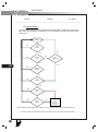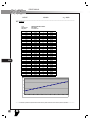
1
instrumentation
Overview
The Blue Bird All American instrument cluster uses all electronic analog guages with
stepper motor technology coupled to a microcontroller that provides the necessary
electrical control. In addition to gauges, this ACTIA® manufactured instrument cluster includes an LCD display panel known as a Message Display Center and gauge
warning indicators which provide illuminated visual alerts to the Driver.
The instrument cluster receives both analog inputs from such components as the
fuel tank sender and instrument panel dimmer switch; binary inputs from brake and
directional signal switches; and digital signals from components such as the engine
and transmission control modules, via the J1939 and J1587 data buses.
The instrument cluster comes with several modes of operation. The system is in
Sleep Mode when the battery power is applied to the cluster with no other activity.
In this mode the microprocessor deactivates the power maintain output resulting in
low power draws of less than 3mA to support the clock. When the instrument cluster
sences a change to an input signal such as turning the iginition key on or turning on
the headlights, the cluster wakes up and then decides which mode to enter depending on which input is active. Limited Mode is a stand by mode entered when there
is battery power available and the iginition is turned off, but other input signals are
requiring the system to operate such as hazard warning lights or brake interlock request. Another mode of operation is the Start-Up Mode. This mode is entered when
the iginition is turned on. When the start-up mode is initiated the cluster will go
through a functional diagnostic test, if the self-test option is enabled (default). During this test you will see the gauge pointers drive to zero position (pause) then move
to half scale (pause) and then move to full scale (pause) before returning to the zero
Warning Bank
Speedometer
Air Brake
Pressure Gauges
603
Tachometer
Coolant Temp Gauge
Warning Bank
Oil Pressure Gauge
Fuel Gauge
Information Display Screen
Actia
1
APPENDIX
L
SERVICE MANUAL
604
position, and finaly going to the commanded position. During this time all warning
lights will perform a lamp check by turning on for 5 seconds, and the three different audible tones will be checked by turning on for 1 second. During this start-up
mode, the microprocessor also monitors all the inputs. If a problem is detected an
error message will be displayed and the gauges will wag to flag the communication
failure. The Ignition Mode is the normal operational mode of the system and is active
as long as the ignition switch is on. When the ignition is turned off the microprocessor will zero all gauges, except the fuel gauge which will remain at its last command
position. The Self-Diagnostic Mode is entered through a menu selection. The selfdiagnostic tests include the gauges, LCD, warning lights, binary inputs, analog inputs
and binary outputs. Detailed specifications can be found in the Message Display Center section of the appendix.
The backlighting on this instrument cluster is adjustable through an internal
dimmer. This is done using the two buttons on the face of the cluster. The backlight
color can also be changed through the setting and diagnostics menu accessed using
the same two buttons on the face of the cluster. Backlight colors are blue, light blue,
white, red and green. The white LCD and amber pointer backlights are not adjustable.
The cluster also uses its microprocessor to compute logic required for certain
units to function. When the logic is satisfyied, an output is generated and sent to
these units to satisfy their operational needs. Units requiring logic outputs include
Speed Detect used in the brake interlock system, Seat Belt Logic used for alarms and
Lift Authorization used to supply power to deploy the handicap wheelchair lift.
The instrument cluster is a sealed unit with no serviceable parts including gauges, lights and buzzers. If your cluster is found to be defective, it is replaced in whole
as a unit.
Appendixes In This Chapter
Appendix 1. My08 Blue Bird Corporate Cluster Functional Specification. This ACTIA publication was created especially for Blue Bird and details the operation of the
instrument system including a detailed explanation of the Message Display Center’s
menus and diagnostic capabilities.
L
instrumentation
Instrument Cluster Removal
The instrument cluster is designed for easily removed from its housing by means of
seven screws around the perimeter of its face. The instrument cluster is not designed
for disassembly and is removed as a unit.
1. Turn the iginition switch to the off position and remove the key. Lower the
steering wheel to the bottom of its travel.
2.Remove the seven machine screws from around instrument panel’s perimeter.
3. Carefully pull the instrument assembly away from the dash housing and tilt
face down.
4. Disconnect the electrical connectors from the back of the instrument cluster
and remove unit.
Testing a Gauge By Substitution
To help quickly determine if a suspected gauge is faulty, the harness connnector
from an adjacent gauge can be temporarily substituted.
1. Label and remove the wiring harness from the gauge in question.
2. Label and remove the wiring harness from an adjacent gauge.
605
3. Plug the connector from the known “good” gauge into the suspect gauge.
4. Support the instrument cluster in a safe position.
5. Turn the ignition switch to the “ON” position. Start the engine if necessary.
6. Check whether the suspect gauge now indicates a value. If it does not, the
gauge may be faulty. If the gauge indicator needle now indicates a reading,
the original malfunction is probably not due to a faulty instrument panel
harness. A gauge test can determine if the gauge itself needs to be replaced.
There are other test and troubleshooting techniques available in Appendix 1.
Refer to the manufacturer’s service manual for instructions regarding signals
originating from the engine ECM or transmission TCU. Electrical diagrams
can also be found in this manual to aid in troubleshooting the entire circuit.
L
SERVICE MANUAL
606
L
instrumentation
110715-F
02/19/09
Page 1/69
______________________________________________________________________________________
52765 Bridger Court
Phone:
574 264 2373
Elkhart, IN 46514
Fax:
574 295 7585
USA
www.actia.com
MY08 Bluebird Corporate Cluster Functional
Specification
Client approval:
Company:
Bluebird
Name:
John Williams
Signature and Date:
Effected Software:
607
110940v00_0X SOF,BLUEBIRD CORP CLUSTER
NOTICE OF PROPRIETARY INFORMATION
This document and its contents are proprietary to Actia.
This publication and its contents may not be reproduced or distributed for any purposes without the written
permission of Actia.
Classification
Instrument Cluster: Appendix 1
No
Confidential. ACTIA
Confidential. Client
Written
Reviewed
By
Date
S Myers
11.07.07
ACTIA Ref.
Revision
Specifications
110715
F
© 2009 Any reproduction of this document whether total or
partial without the written consent of ACTIA is forbidden.
Page 1
Format
US Letter
MY08 BBCC
Approved
______________________________________________________________________________________________________
© 2009 Any reproduction of this document whether total or partial without the written consent of ACTIA is forbidden
1
APPENDIX
L
SERVICE MANUAL
110715-F
02/19/09
Page 2/69
______________________________________________________________________________________
Revision Table
Rev
By
Date
Software
Description
0
R Parks
11-26-2007
1110940v00_01
Original Draft; Out for comment
1
R Parks
11-29-2007
Updated per comments from Kevin Decker (10.6.1, 7.1.2.3, 7.1.2.4, 7.1.2.5,)
2
R Parks
01-16-2008
Changed tachometer to 5000 rpm (5.1.2), Removed Stop light warning light (5.3.12),
Removed stop light inhibit configuration bit (7.3.6), Added Brake Interlock priority
message (7.1.3.25), Removed retarder warning light (5.3.11), Added retarder priority
message (7.1.3.26), Added source address to retarder message (6.5). Changed engine
shutter solenoid activation level (5.5.2) Removed range inhibit warning light (5.3.8),
Added range inhibit priority message (7.1.3.27), Added Trans fluid life / Trans fluid
filter / Trans service priority messages (7.1.3.28, 7.1.3.29, 7.1.30, 6.5)
3
R Parks
02/12/2008
Added Seat belt warning light & audible alarm (10.6.1, 5.3.18), Added device auto
detect feature, Assigned LED designators to all warning & indicator lights (5.1, 5.3),
Changed symbol references (5.3.1, 5.3.2, 5.3.4, 5.3.10). Added screen shots to LCD
parameters. Added suspension air to the set up menu. (7.3.7)
4
R Parks
02/27/2008
5
S Myers
3.6.08
Replaced the “m & t” button references with “lower & upper” (All), Removed the
remote dimmer input (10.6.1), Added dimmer adjustment to the LCD menu (5.2 &
7.2.3), Added scroll description (7.1), Added suspension air screens (7.1.2.5 &
7.3.7), Added Transmission & ABS diagnostic screens (7.28 & 7.29), Added self test
screen (7.3.3)
Section 10.6—Updated the Cluster Connector Pinout table to match the hardware.
Fuel level moved to pin 34, All designations from pin 11- pin 17 moved down one
pin. Hi Hydraulic Oil Temp/Hyd Brake Fail moved down to pin 17. All
designations from pint 22 – pin 25 move down one pin. Pin 25 changed to spare.
Seat belt moved to pint 32. Added a little more description to the pins. Added
wakeup designation column for clarity on Hardware or Software configurable
wakeup. Also added a column for individual connector pinout for clarity.
Section 7.27— Corrected the Engine Diag display to show the J2012 information
instead of the SPN/FMI for GM only.
Section 7.28—Corrected the Trans Diag display to show the J2012 information
instead of the SPN/FMI.
Section 5.1—Added stepper motor designators to each gauge for clarity on location
Section 5.1.4—Changed scale type to linear and max scale to be 100 psi to match the
dial. Also corrected direction to be CCW to match dial
Section 5.1.7—Corrected trigger to be for rear air instead of front air. Probably a
cut/past error.
Combined all indicator lights into single table in section 5.3 for clarity
Section 7.2—corrected some of the menu item numbers as they were off by one.
Section 5.1.6—Corrected gauge direction
Moved and restructured Brake Interlock logic tables. Removed No Brake Interlock
table. Removed Stop lamp as it is not used anymore to show Brake peddle
depressed.
Added a note to Drive mode screen section to show that Quad 2 has no user
configuration and will be skipped when navigating between quadrants.
Added feature programming section to show config bit
6
S Myers
3.21.08
608
Moved 1939 Table to the back
Changed Test panel binary inputs to work with the Input module spare binaries.
Added reference to Bus Type config byte to brake interlock logic tables to show
reference to BBCV.
Corrected the configuration bytes
Added SA 16 to retarder message detail in 1939 table
Corrected the logic of turning odo on with ignition off. It is not done by dimmer
anymore, but by headlights or button push
Added Engine ID feature detail
______________________________________________________________________________________________________
© 2009 Any reproduction of this document whether total or partial without the written consent of ACTIA is forbidden
L
1
APPENDIX
instrumentation
110715-F
02/19/09
Page 3/69
______________________________________________________________________________________
7
S Myers
4.1.08
8
S Myers
4.2.08
9
P
English
4.11.08
10
S Myers
5.12.08
11
S Myers
5.15.08
12
S Myers
6.12.08
13
S Myers
6.17.08
Renamed section 6.5.5 to throttle interlock instead of brake interlock
Updated Plug and play section description to remove roll call references
Added priority message for data link missing
Removed 1850 and GMLAN references from Allison transmission in section 2.
Section 6.6--Corrected pin references and clarified message broadcast and trigger
information for all sent messages.
Corrected all section referencing pin 25 as service brake to be pin 24
Removed duplicate info on Lift Authorization logic flow chart that referenced sent
messages.
Updated Dial face backlight color descrip with color percentages based on WCC
application
Section 8--Changed Backlight setting feature to DIMMER and added a backlight
color selection feature. Need new screen shot.
Updated all pin out references to match table.
Updated lift authorize flow chart for clarification
Updated missing suspension air pin info as it is the same as front air but only in
hydraulic busses.
Added description to backlight section for clarity
Moved brake interlock logic flow chart and modified for clarity
Modified section 9 to change the way brake system and its option setting are
configured.
Updated section 8.7.5 and 8.7.6 to match the new brake system config and option
settings.
Sections 7.1.1-7.1.5 changed all screen shots to reflect change in quadrant 2.
Ammeter if available will now be displayed on line with voltage, current gear will
now always have its own line, and depending on active options quad 2 will adjust
from 2 to 3 lines as appropriate.
Finished updating all screen shots for display configurations, messages and menus
Moved Data link out of instrument diag submenu and restructured for clarity
Updated all screens in Setup and Diag menu to take advantage of the large screen
and stay consistent in navigation features.
Modified Setup menu to be Configuration menu to clear up confusion between this
and the diag and setting menu.
Updated section 4.1.1 by changing dimmer to headlight for ODO limited mode
trigger and added the buttons
Section 4.2.1 Added a little better description of how long the clusters stays in
Limited mode when wakeups are used.
Section 5.3—Clarified and corrected Park Brake lamp function in the table.
Section 5.3—Removed Beep 1 from Wait to Start to match A3 multigauge function
Section 5.3—Added Amber Lamp to Check trans DM1 trigger to match A3
Section 5.3—Added Amber Lamp to Low Coolant DM1 trigger to match A3
1939 message table—updated EBC1 to show SA of 0B instead of 11 as all of these
are represented in HEX.
1939 message table—updated the SA for all sent messages to 17 for same reason.
This matches A3 function.
Out dented Audible alarm section 5.4 to be section 6 and clarified definition of
alarms.
Added more description to section 5.3 for associated displays and warning alarms
and how they are acknowledged
Referenced High Exhaust temp Lamp trigger and alarm to be the same as the High
Exhaust temp Display message.
Corrected seat belt alarm in lamp table
Corrected Data sources for MIL and LOW FUEL PRESSURE lamps in lamp table
Out dented binary output descriptions for clarity
Removed duplicate Brake Interlock flow chart in section 9.1.4
Added A3 only reference to Brake interlock logic flow chart in section 8.6.5
Defined Brake interlock logic in section 9.1.3.3 as the display logic for BBCV only.
Added Throttle Interlock message reference to lift authorization Flow Chart for
clarity
Moved Brake Interlock flow chart to message sent section for clarity
609
______________________________________________________________________________________________________
© 2009 Any reproduction of this document whether total or partial without the written consent of ACTIA is forbidden
1
APPENDIX
L
SERVICE MANUAL
110715-F
02/19/09
Page 4/69
______________________________________________________________________________________
14
15
S Myers
S Myers
6.19.08
6.25.08
16
S Myers
6.26.08
17
S Myers
7.1.08
18
S Myers
7.10.08
B
S Myers
7.10.08
610
Removed LOW FUEL PRESSURE binary trigger from the warning light table and
from the warning bank input table per John Williams statement that CUMMINS
ISLG is the only CNG we support and that is triggered with the voltage on pin 10 of
the cluster.
Corrected audible alarms associated with warnings per Michel markups
Changed byte 0 bit 7 of config table from unused to clock mode
Corrected connector pinout to show 1939 on pins 3&4 and GMLAN on pins 5&6
Updated Cruise control lamp function to use States instead of Active to match
current A3 functionality that was never documented before per Michel.
Section 9.1-- Changed how Quad 1 is toggled and how Quad 3 and 4 are navigated
between to make the commonly used odometer much easier to toggle and the lesser
used Parameter (Quad 3) the default selection and the even lesser used clock (Quad
4) the only one that requires more that one button push and the only one to require
the double button push to get to.
Section 9.2—Updated instruction on toggling between quad 1 display options and
how to reset trip odo.
Section 9.3—corrected verbiage in quad descrip for 2A to say PRNDL instead of
requested gear.
Section 9.4.1—Added more description to how quad 3 is changed by the end user
Section 9.5—Added description on how quad 4 is changed by the end user
Section 3—Added note to provide updated drawings of the dials to BB if a spec
change effects the dial art Per John Williams request to do so.
All references to Park Brake input PIN 22 changed from AH to AL. Per John
Williams request
Section 5.4—Changed seat belt audible alarm from beep 1 to beep 3 per John
William’s request for a unique beep for seatbelt logic. Also changed trigger to only
reference flow chart in section 5.4.1
Section 5.4.1—Changed seat belt logic to actuate if the input is high (unbuckled)
instead of Low (buckled) per John Williams
Section 6.1—Added Beep 3 tone definition for seat belt as continuous with same
frequency as Beep 2 per John Williams.
Section 8.6—Removed water in fuel from messages sent per John Williams
Section 9.4.2—corrected brake interlock display function reference to reference the
correct table in section 9.4.2.1
Section 9.4.2—Changed retarder applied audible alarm to NONE per John Williams
Section 10.6.4—Added reference only comment to screen shots for I/O status
Section 9.4.2—Updated headlight alert logic to closer match A3 function per
Michel’s notes.
Section 6.1—Updated tone definition to change beep to freq and both beep 1 and
beep 2 repetition to 2Hz per Michel’s notes on how the software actually works and
to closer match A3
All changes for this rev are additions original project requirements
Section 1—Added FMVSS/CMVSS 101 requirement per John Williams
Section 4—Added Brake interlock request limited mode note per John Williams
Section 5.4—Removed triggers and alarms for High Hydraulic Oil temp as it is no
longer required per John Williams
Section 5.4—Changed Hydraulic Brake Failure international icon to text BRAKE
PRESSURE per John Williams (was originally specified to be BRAKE SYSTEM
but was inadvertently changed to the international symbol after rev 2 of the spec.
Some time after this was implemented in Alpha it was requested that the symbol be
moved down and its place be taken by text BRAKE PRESSURE so that both were
available on one dial)
Section 7.1—Modified Speed Detect output logic per John Williams. Added the
Brake interlock request and Battery Controlled Lift Config requirements. Added
section 11.10 for this new config.
Section 12.2—Added byte for the above mentioned Battery Controlled Lift Config.
Section 7.3—Added Brake Interlock request input and Battery Control Lift Config to
Lift Authorize logic per John Williams.
Section 8.6.2.1—Modified Brake interlock logic per John Williams
Changed PIN 25 from spare to brake interlock alarm BIN AL per John Williams
______________________________________________________________________________________________________
© 2009 Any reproduction of this document whether total or partial without the written consent of ACTIA is forbidden
L
1
APPENDIX
instrumentation
110715-F
02/19/09
Page 5/69
______________________________________________________________________________________
7.14.08
7.22.08
7.24.08
Changed PIN 36 to brake interlock request BIN AL per John Williams. This will be
a wakeup
Added section 4.2.3 to describe limited mode for Brake interlock request wakeup per
John Williams.
Changed PIN 27 from Alternator to Spare per John Williams
Changed PIN 33 from Spare to Lift door not open per John Williams
Changed PIN 35 to Brake Interlock Set/locked per John Williams
Section 8.6.1—Added brake interlock request to service brake message sent trigger
per John Williams
Section 9.4.2—Changed Alternator Fail PIM logic per John Williams
Section 9.4.2—Removed Hi Hydraulic Oil Temp PIM per John Williams
Section 9.4.2—Removed Hydraulic Brake Fail, Low Front and Rear Air PIM’s per
John Williams
Section 9.4.2—Changed Water in fuel PIM data and logic to 1939 per John Williams
Section 13—Added FMVSS/CMVSS 101, 105, 135 per John Williams
Changed Water in Fuel SA to 0 and from TX to RX in the 1939 message table per
John Williams
Section 14.8—Removed MIL input as it is no longer needed and moved all other
inputs except test inputs to cluster connector per John Williams
Changed section 8.6.2.1 to say Throttle interlock instead of Brake interlock to reduce
confusion between this and section 9.4.2.1 brake interlock message logic matrix.
Section 9.4.2.1—updated the brake interlock PIM logic matrix per John Williams.
Added Interlock Alarm and vehicle speed. Changed displays to flashing and added
different alarms per John Williams.
Section 11.7—Updated bus type config description as the Brake interlock logic is
now not exclusive to BBCV but will be used on D3 as well.
Section 7.1—Added park brake set to Speed detect logic per John Williams
Section 14.6—Added Fast Idle input to PIN 27 as BIN AL
Section 8.6—Added Fast Idle message
Section 10—Added an Air Brake PSI view screen to setting and diagnostic menu for
Pretrip Brake Inspections per John Williams
Moved BRAKE interlock Alarm from pin 25 to pin 27 and moved Fast Idle from 27
to 25 and made it AH per John Williams
Section 1—Added “in writing” to criteria for standard deviation by customer per
John Williams
Section 4.2.3—changed the AH to just Active to avoid duplicate info and any
confusion between Active and Analog.
Corrected spelling in D404 row of lamp table
Section 5.4.1—Added park brake decision to logic of seatbelt per John Williams
Section 6.1—Added a little more description to the Audible alarm section to clarify
the numbers in the table.
Section 7.3—Moved battery control Lift config decision to come after Ignition
decision per John Williams
Section 8.6.2.1—corrected the verbiage to only refer to throttle interlock. Removed
reference to A3 as this applies to both A3 and CV per John Williams. Also updated
11.7 to say that bus type config has no effect on application any more.
Section 9.4.2—Changed Alternator Fail to have acknowledgeable alarm.
Section 9.4.2—Corrected WIF SPN from 197 to 97.
D402—ABS alarm changed to self cancel in 5 sec per John Williams
Section 7.3—moved “in neutral gear” decision above park brake set and changed
how it interacts with batter cntrl lift decision per John Williams
Section 9.4.2—chanced Lift not Stowed alarm and Battery Voltage alarm to Beep
1/for 5 sec per John Williams
Section 9.4.2—added detail that both turn signals at the same time do not apply to
turn signal warning logic per John Williams
Section 9.4.2—Changed WIF alarm to be acknowledgeable
Section 9.4.2—Removed the ignition of portion of the headlight reminder logic, per
John Williams. I also added the 2 min duration as this is how it currently works.
Section 9.4.2—Changed duration of alarm for ATC, DPF and High exhaust temp to
5 sec per John Williams
611
______________________________________________________________________________________________________
© 2009 Any reproduction of this document whether total or partial without the written consent of ACTIA is forbidden
1
APPENDIX
L
SERVICE MANUAL
110715-F
02/19/09
Page 6/69
______________________________________________________________________________________
7.30.08
8.15.08
8.25.08
9.4.08
9.5.08
612
C
S Myers
10.14.08
10.27.08
110940v01_17
11.10.08
D
S Myers
12.11.08
110940v01_18
12.16.08
12.17.08
E
S Myers
1.9.09
110940v01_18
1.20.09
F
S Myers
2.6.09
110940v01_21
Section 9.4.2—Change alarm for Range Inhibit, Trans oil life, filter and service to
NONE per John Williams
Section 9.4.2.1—changed alarm durations for several of the alarms per John
Williams
Section 12.2.2—Corrected Engine Type bit values and descriptions to match
software
Removed Hydraulic designation from D404 and added comment to trigger to only
use this if configured as English. Added D405 for Metric brake fail function.
Corrected Air gauge warning lamps to text instead of symbol. All of which to
satisfy the changes made to the dial per John Williams.
Section 9.4.2.1—Added note that brake interlock is NOT acknowledgeable per John
Williams.
Section 6.1—Added details of general acknowledgement and reoccurrence of alarms
per John Williams.
Section 5.4—Per previous documentation received from BB on how the engine
should react to PTC messages I updated Stop engine and Engine Warning lamps to
work with the DPF message.
Section 9.4.2.1—I added Scenario numbers to each row of the Brake Interlock
display table for clarity.
Section 12.2—Allocated another bit to the Engine Type config setting to allow for
future unknown CAT or Cummins Engines to register with Engine ID message.
1939 Table—changed the SA for retarder message to 0F, 10 and 29 based on engine
and transmission specifications.
Section 11.3—Removed the requirement for Beep 2 to sound for turn signal If turn
signal click config is disabled
Section 7.1—Reconstructed Speed Detect output flow chart and added notes for
clarity. (corrected Ignition on decision outcome 9/8/08)
Section 7.3—Reconstructed Lift Authorization output flow chart and added notes for
clarity
Section 8.6.2—Slightly modified the verbiage in Throttle interlock message
description logic to clarify that it is sent during Lift Authorization output active.
Added comment about fuel gauge initial position in section 4.3
Section 11 & 12—added detail to make certain configurable feature only accessible
by diagnostic tool after 25 mi. Per Jim Halpin
Section 11.7—Added function to the Bus Type Config to invert the Park Brake and
Fast Idle binary input logic for BBCV per Jim Halpin
Added PIN 36 AL to Wait to start for BBD3 and BBCV per Jim Halpin
Section 5.4—Split D406 Park Brake lamp to double as Brake Fail when configured
as Metric. Spec only change for clarification, software is correct.
Added Section 9.4.1.1 to describe calculation and display of the Average Fuel
Consumption resettable trip. This was to give BB a resettable trip average fuel per
John Williams.
Section 10.6—Changed clock set menu timeout from 5 sec to 15 sec per John
Williams
Section 5.2—Changed how the dimmer adjustment works Per John Williams
Section 5.4—Added SPN 65000 as a trigger for ENGINE WARN lamp for Gateway
support.
Section 8.6.1—removed brake interlock request as a requirement for the service
brake message to be sent per John Williams
Section 11.11—Added a configuration to the Config menu to Enable or Disable the
seatbelt logic. This includes “auto detect” feature to enable the logic if input
becomes active. Used Byte 1, bit 7 of config bytes.
Section 5.1.1—Swapped MPH and KMH LED designations for dial face art change.
Software needs updated as well.
Section 5.4—Park brake lamp/alarm logic changed to shut off after 2 min. to match
current A3 gauge logic. This is a document only change and confirmed by John
Williams.
Section 9.4.2—Added 30 sec delay to Alternator Fail and Low Voltage Error
triggers per John Williams.
Section 8.2—Added final gateway spec info as well as more definition for device ID
______________________________________________________________________________________________________
© 2009 Any reproduction of this document whether total or partial without the written consent of ACTIA is forbidden
L
1
APPENDIX
instrumentation
110715-F
02/19/09
Page 7/69
______________________________________________________________________________________
messages.
Section 11.8—Added notes to clarify what changes with GM 1850 config
Section 9.4.1—Added display info to show which Parameters were not available
when configured for GM 1850
Section 9.4—Added note that Quad 3 defaults back to Trans Temp on ignition cycle.
This is not a software change but additional info for the spec and confirmed by John
Williams.
613
______________________________________________________________________________________________________
© 2009 Any reproduction of this document whether total or partial without the written consent of ACTIA is forbidden
1
APPENDIX
L
SERVICE MANUAL
110715-F
02/19/09
Page 8/69
______________________________________________________________________________________
Table of Content
1. PURPOSE.............................................................................................................................................................................11
2. SCOPE..................................................................................................................................................................................11
3. RELATED DOCUMENTS .................................................................................................................................................11
4. MODES OF OPERATION.................................................................................................................................................12
614
4.1. SLEEP MODE ........................................................................................................................................................................12
4.1.1. Power supply ..............................................................................................................................................................12
4.1.2. LIN Devices ................................................................................................................................................................12
4.1.3. Clock ...........................................................................................................................................................................12
4.2. LIMITED MODE ....................................................................................................................................................................13
4.2.1. Display Odometer & Clock in LCD............................................................................................................................13
4.2.2. Hazard warning lights ................................................................................................................................................13
4.2.3. Brake Interlock Request..............................................................................................................................................13
4.3. START-UP MODE .................................................................................................................................................................13
4.3.1. Start-up up Self-test Option ........................................................................................................................................13
4.4. IGNITION MODE ...................................................................................................................................................................14
4.5. SLEEP MODE ........................................................................................................................................................................14
4.6. SELF-DIAGNOSTIC MODE ....................................................................................................................................................14
4.7. TEST PANEL MODE ..............................................................................................................................................................15
5. IGNITION MODE ..............................................................................................................................................................16
5.1. GAUGE DISPLAY ..................................................................................................................................................................16
5.1.1. Speedometer................................................................................................................................................................16
5.1.2. Tachometer .................................................................................................................................................................16
5.1.3. Fuel Gauge .................................................................................................................................................................16
5.1.4. Oil Pressure Gauge ....................................................................................................................................................17
Coolant Temperature Gauge ................................................................................................................................................17
5.1.5. Front Air Gauge .........................................................................................................................................................17
5.1.6. Rear Air Gauge...........................................................................................................................................................17
5.2. BACKLIGHTING ....................................................................................................................................................................18
5.2.1. Gauges ........................................................................................................................................................................18
5.2.2. LCD ............................................................................................................................................................................18
5.2.3. Pointer ........................................................................................................................................................................18
5.3. WARNING BANK INDICATORS ..............................................................................................................................................19
5.4. LAMP GENERAL DETAIL ......................................................................................................................................................19
5.4.1. Seat Belt Logic ............................................................................................................................................................22
6. AUDIBLE ALARM .............................................................................................................................................................23
6.1. TONE DEFINITION ................................................................................................................................................................23
6.1.1. Turn Signal Click ........................................................................................................................................................23
7. BINARY OUTPUTS............................................................................................................................................................24
7.1. SPEED DETECT .....................................................................................................................................................................24
______________________________________________________________________________________________________
© 2009 Any reproduction of this document whether total or partial without the written consent of ACTIA is forbidden
L
1
APPENDIX
instrumentation
110715-F
02/19/09
Page 9/69
______________________________________________________________________________________
7.2. SHUTTER SOLENOID.............................................................................................................................................................25
7.3. LIFT AUTHORIZATION ..........................................................................................................................................................26
8. COMMUNICATION ..........................................................................................................................................................27
8.1. J1939 AUTO DETECT FUNCTION ..........................................................................................................................................27
8.2. ENGINE ID ...........................................................................................................................................................................27
8.3. PLUG AND PLAY FUNCTION .................................................................................................................................................30
8.4. J1939 COMMUNICATION ERRORS ........................................................................................................................................30
8.5. GMLAN COMMUNICATION ERRORS ...................................................................................................................................30
8.6. MESSAGES SENT ..................................................................................................................................................................30
8.6.1. Service Brake ..............................................................................................................................................................30
8.6.2. Throttle Interlock (A3/D3 only) ..................................................................................................................................30
8.6.3. Park Brake ..................................................................................................................................................................32
8.6.4. Fast Idle ......................................................................................................................................................................32
9. MESSAGE DISPLAY CENTER........................................................................................................................................33
9.1. DRIVE MODE SCREEN ..........................................................................................................................................................33
9.2. QUADRANT 1 .......................................................................................................................................................................34
9.3. QUADRANT 2 .......................................................................................................................................................................36
9.4. QUADRANT 3 .......................................................................................................................................................................37
9.4.1. Parameters..................................................................................................................................................................37
9.4.2. Priority Messages .......................................................................................................................................................38
9.5. QUADRANT 4 .......................................................................................................................................................................44
10. SETTINGS AND DIAGNOSTIC.....................................................................................................................................45
10.1. AIR BRAKE PSI..................................................................................................................................................................45
10.2. SET UNITS..........................................................................................................................................................................45
10.3. CONTRAST .........................................................................................................................................................................46
10.4. DIMMER .............................................................................................................................................................................46
10.5. BACKLIGHT COLOR ............................................................................................................................................................46
10.6. SET CLOCK ........................................................................................................................................................................46
10.7. INSTRUMENT DIAGNOSTICS ...............................................................................................................................................47
10.7.1. Gauge Test ................................................................................................................................................................47
10.7.2. Lamp Test..................................................................................................................................................................47
10.7.3. LCD Test...................................................................................................................................................................47
10.7.4. I/O Status ..................................................................................................................................................................48
10.7.5. I/O Status ..................................................................................................................................................................48
10.8. DATA LINK ........................................................................................................................................................................48
10.9. READ PARAMETERS ...........................................................................................................................................................49
10.10. ENGINE DIAGNOSTIC .......................................................................................................................................................49
10.11. TRANS DIAGNOSTIC .........................................................................................................................................................50
10.12. ABS DIAGNOSTIC ............................................................................................................................................................50
615
11. CONFIGURATION MENU .............................................................................................................................................51
11.1. BUZZER TIME OUT ENABLE ...............................................................................................................................................52
11.2. TEST PANEL .......................................................................................................................................................................52
11.3. TURN SIGNAL CLICK..........................................................................................................................................................52
11.4. AMMETER DISPLAY ...........................................................................................................................................................52
11.5. BRAKE SYSTEM TYPE ........................................................................................................................................................52
11.6. APPLIED/SUSPENSION AIR .................................................................................................................................................52
11.7. BUS CONFIGURATION TYPE ...............................................................................................................................................53
11.8. ENGINE CONFIGURATION TYPE..........................................................................................................................................53
11.9. SELF TEST..........................................................................................................................................................................53
11.10. BATTERY CONTROLLED LIFT ...........................................................................................................................................53
______________________________________________________________________________________________________
© 2009 Any reproduction of this document whether total or partial without the written consent of ACTIA is forbidden
1
APPENDIX
L
SERVICE MANUAL
110715-F
02/19/09
Page 10/69
______________________________________________________________________________________
12. FEATURE PROGRAMMING.........................................................................................................................................54
12.1. BYTE 0...............................................................................................................................................................................54
12.2. BYTE 1...............................................................................................................................................................................54
12.3. DIAGNOSTIC COMMANDS ..................................................................................................................................................55
13. RELATED STANDARDS.................................................................................................................................................55
14. GLOSSARY/ABBREVIATIONS.....................................................................................................................................56
RESISTIVE FUEL SENDER ............................................................................................................................................................57
14.1. VOLTAGE FUEL SENDER ....................................................................................................................................................58
14.2. AIR PRESSURE SENSORS ....................................................................................................................................................59
14.2.1. 174 PSI .....................................................................................................................................................................59
14.3. AMMETER ..........................................................................................................................................................................60
14.4. J1939 TABLE OF MESSAGES ..............................................................................................................................................61
14.5. GM LAN TABEL ...............................................................................................................................................................63
14.6. CLUSTER CONNECTOR .......................................................................................................................................................64
14.7. CLUSTER MATING CONNECTORS .......................................................................................................................................65
14.8. WARNING MODULE BINARY INPUT CONNECTOR ...............................................................................................................65
15. APPENDIX B.....................................................................................................................................................................67
15.1. SERVICE SET ODOMETER FEATURE -- ................................................................................................................................67
15.2. LIMITED FUNCTION............................................................................................................................................................67
15.3. SETTING THE UNITS ...........................................................................................................................................................67
15.4. SETTING THE ODOMETER VALUE .......................................................................................................................................68
616
______________________________________________________________________________________________________
© 2009 Any reproduction of this document whether total or partial without the written consent of ACTIA is forbidden
L
1
APPENDIX
instrumentation
110715-F
02/19/09
Page 11/69
______________________________________________________________________________________
1. PURPOSE
This document is the design specifications for the development of a corporate cluster for Bluebird Bus
Corporation. Initially to be used on the D3 and CV bus lines.
The instrumentation is based on gauges with stepper motor technology, married to a microcontroller that
provides the necessary electrical control. Circuit provisions are included to assure compliance with SAE
J1455 “in cab” standards and Bluebird electrical SP13 environmental specification.
All gauges and indicator or warning lamps as well as displays are to comply with FMVSS/CMVSS 101
standards unless deviation is approved by the customer in writing.
2. SCOPE
This document covers the operational specifications of the instrument panel and gauge system for use in
Bluebird school buses. Engine, transmission, and ABS systems used in this application are listed in the
table below:
Engines
Cummins ISB07 (Diesel) / ISC07 (Diesel) /
ISLG (J1939)
GM 8.1L (Gas) ECM (J1850* & GMLAN)
CAT C7 (Diesel) (J1939)
Transmissions
Allison 2000/2500 / 3000 (1939)
ABS Systems
Wabco Hydraulic Systems (J1939)
Bendix EC30 Air Systems (J1939)
Bendix EC60 Air Systems (J1939)
*Note: J1850 communications facilitated through Actia J1850 to J1939 converter module (Actia # 106622)
617
3. RELATED DOCUMENTS
For more detail on functional or visual details of this instrument system, the following documents must be
consulted:
• 110763 Dial face with Air Gauges-If spec change effects graphics, updated art must be supplied to
the Customer for approval and documentation on their end.
• 110764 Dial face without Air Gauges- If spec change effects graphics, updated art must be supplied
to the Customer for approval and documentation on their end.
______________________________________________________________________________________________________
© 2009 Any reproduction of this document whether total or partial without the written consent of ACTIA is forbidden
1
APPENDIX
L
SERVICE MANUAL
110715-F
02/19/09
Page 12/69
______________________________________________________________________________________
4. MODES OF OPERATION
[left
or
right
turn,
headlight, button press or
Brake Interlock Request if
configured]
and
not
ignition
Sleeping
Mode
Limited
Mode
End limited
mode
[left
or
right
turn,
headlight, button press or
Brake Interlock Request if
configured]
and
not
ignition
Ignition
Ignition
Not
Ignition
Diagnostic
request
Start-up
Mode
Start-up
completed
Ignition
Mode
End
Diagnostic
Self
Diagnost
ic Mode
618
4.1. Sleep Mode
If battery power is applied to the system with no other activity, it will be in sleep mode. When the
system is in Sleep Mode the microprocessor is stopped.
4.1.1. POWER SUPPLY
The system exits Sleep Mode when one of the wake-up inputs becomes active. When the cluster
wakes up, it first begins to control the power supply by activating the power supply maintain
output. It then decides, depending on which wake up input is active, what mode must be entered.
When the system goes back to sleep after the deactivation of the wakeup input, it simply
deactivates the power supply maintain output.
4.1.2. LIN DEVICES
All LIN devices will remain awake for 10s after loss of wakeup. The master will stay awake for 4
seconds after loss of IGN and 10 seconds after loss of any other wakeup.
4.1.3. CLOCK
The clock will remain awake in the background as long as battery power is applied. It will only
display on LCD when in Limited or Ignition mode.
______________________________________________________________________________________________________
© 2009 Any reproduction of this document whether total or partial without the written consent of ACTIA is forbidden
L
1
APPENDIX
instrumentation
110715-F
02/19/09
Page 13/69
______________________________________________________________________________________
4.2. Limited Mode
The system runs in limited mode when battery power is available, the ignition input is not active
but other input signals are requiring the system to operate. The system exits limited mode when
the ignition becomes active or the input signals that caused the system to wake-up become inactive.
4.2.1. DISPLAY ODOMETER & CLOCK IN LCD
The odometer and Clock is readable with the ignition off when the Headlight input is Active or
Mode or Trip button is pressed. The cluster will go back to sleep mode if the Headlight input is not
active or 15 sec after the mode or trip was pressed.
4.2.2. HAZARD WARNING LIGHTS
The right and left turn icons are operational with the ignition off when the hazard lights are turned
on (right and/or left turn binary inputs high).
4.2.3. BRAKE INTERLOCK REQUEST
When this input is Active the cluster power supply will wake up only to check the Battery control
lift config and depending on the setting will either carry out the logic for the outputs as described in
section 7 of this document or go back to sleep.
619
4.3. Start-Up Mode
The ignition binary input is used to sense if the key switch is on or off. The cluster enters start-up
mode when the ignition is on. If the start-up self-test option is enabled, the system will go through
the functional diagnostic tests described in the start-up self-test option section.
If the self-test option is disabled the gauges should drive to zero, with the exception of fuel which
remains at its last commanded position, then default to actual values received by data buss
messages/senders at startup.
All warning lights will perform a lamp check by turning on for 5 seconds and then go out. After
lamp check, active warning lights will turn.
The cluster will determine which data buses are connected and which devices are present. Error
messages will display if a data bus is missing or a device that had been previously found is now
missing. If the data bus should fail, a communications error should be displayed on the LCD, and
the gauges will wag to flag the communication failure.
4.3.1. START-UP UP SELF-TEST OPTION
The start up self-test is an option enabled through the setup menu. The factory setting for this
option is enabled.
______________________________________________________________________________________________________
© 2009 Any reproduction of this document whether total or partial without the written consent of ACTIA is forbidden
1
APPENDIX
L
SERVICE MANUAL
110715-F
02/19/09
Page 14/69
______________________________________________________________________________________
4.3.1.1. Gauges
Gauge pointers will drive to zero position. The pointers will then drive up scale, pausing at ½
scale, before completing the sweep to full scale. The pointers will then return to zero position
before moving to the commanded position.
4.3.1.2. LCD
During the up scale sweep of the pointers, the LCD will turn all its segments on for one second, off
for one second and then display the opening message. The opening message is the Bluebird logo
followed by the software ID, complete with revision level.
4.3.1.3. Warning Lights
Starting at the up scale pointer sweep, all warning lights will turn on for 5 seconds and then go out.
Active warning lights will turn on when the gauges go to their commanded position.
4.3.1.4. Audible Alarm
The audible alarm will sound three different tones for one second each during the up scale swing of
the pointers.
4.4. Ignition Mode
The ignition mode is active as long as the ignition switch is on.
The ignition is the normal operational mode of the system.
620
If the ignition line goes low the micro will zero all gauges, except the fuel gauge which will remain
at its last commanded position, and store any data to the EEPROM before turning the supply off.
After storing the data, the system goes to sleep mode after a delay of approximately 4 seconds.
4.5. Sleep Mode
When the system is in sleep mode the clusters microprocessor goes into low power mode and
draws less than 3 mA to support the clock function.
The system exits sleep mode when one of the wake-up inputs become active. When the cluster
wakes up, it first begins to control the power supply by activating the power supply maintain
output. It then decides, depending on which wake up input is active, what mode must be entered.
When the system goes back to sleep, it simply deactivates the power supply maintain output.
4.6. Self-Diagnostic Mode
The self-diagnostic mode is entered through a menu selection using the LCD. Diagnostics is only
available when the Park Brake is set.
The self-diagnostic includes the following tests:
• Gauges
• LCD
______________________________________________________________________________________________________
© 2009 Any reproduction of this document whether total or partial without the written consent of ACTIA is forbidden
L
1
APPENDIX
instrumentation
110715-F
02/19/09
Page 15/69
______________________________________________________________________________________
• Warning Lights
• Binary Inputs
• Analog Inputs
• Binary Outputs
Detail specifications are found in the Message Display Center section.
4.7. Test Panel Mode
The test cluster mode can only be activated through Actia provided software. When selected, the
software is configured as a production chassis test fixture. The functions below describe the
difference in operation for this mode:
1) An active Binary Input on WB PIN 6 will configure the cluster for Chassis with System Air (If
it is not active it will be configured for a Hydraulic system)
2) An active Binary Input on WB PIN 7 will configure the cluster for Chassis with Applied Air
(front and rear applied air).
621
______________________________________________________________________________________________________
© 2009 Any reproduction of this document whether total or partial without the written consent of ACTIA is forbidden
1
APPENDIX
L
SERVICE MANUAL
110715-F
02/19/09
Page 16/69
______________________________________________________________________________________
5. IGNITION MODE
5.1. Gauge Display
5.1.1. SPEEDOMETER
Data Source
J1939 - PGN65265
GMLAN -TBD
Stepper Range
M404
187°
Movement
Scale
Indicator Light
CW
Linear
0° = 0
187° = 140
MPH – D426
K/mh – D427
Note: Scale units (MPH -Km/h) scale will be noted though dead front indications on the speedometer.
5.1.2. TACHOMETER
Stepper
Data Source
J1939 - PGN61444
GMLAN - TBD
622
M401
Range
Movement
Scale
Warning
Light
WL Trigger
187 °
CW
Linear
0° = 0 RPM
187 ° = 5000 RPM
None
None
Range
Movement
Scale
Warning
Light
WL Trigger
Alarm
WL
Acknowle
Alarm
dge
None
N/A
5.1.3. FUEL GAUGE
Stepper
Data Source
M403
Diesel CL_Pin_34
Gas - CL_Pin_34
90°
CNG CL_Pin_10
CW
Linear
0° = Empty
90° = Full
Alarm
WL
Acknowle
Alarm
dge
Amber –
FMVSS
On if fuel ≤
571-101
12.5%
Table 2
Then off if fuel
Fuel Level
≥ 18% (Gas /
(D428)
Diesel)
Yes/5 min.
Fuel
Beep 1
Reoccur
Pressure
(D429)
Amber –
On if fuel ≤
Text
1.6Vdc
“Low Fuel
Then off if fuel
Pressure”
≥ 1.7Vdc(CNG)
(D429)
______________________________________________________________________________________________________
© 2009 Any reproduction of this document whether total or partial without the written consent of ACTIA is forbidden
L
1
APPENDIX
instrumentation
110715-F
02/19/09
Page 17/69
______________________________________________________________________________________
5.1.4. OIL PRESSURE GAUGE
Stepper
Data Source
Range
Movement
Scale
Warning
Light
CCW
Linear
0° = 0 PSI
90 ° = 100 PSI
Red –
FMVSS
571-101
Table 2
(D430)
M402
90°
J1939 - PGN65263
GMLAN - TBD
Alarm
WL
Acknowle
Alarm
dge
WL Trigger
J1939 DM1SPN100
GMLAN
TBD
-
Continuo Yes/5 min.
us 1
Reoccur
COOLANT TEMPERATURE GAUGE
Data Source
Stepper
Range
Movement
Scale
90°
CW
Linear
0° (C) = 100°F
90° (H) = 260°F
Range
Movement
Scale
90°
CW
Linear
0° = 0 PSI
90° = 150 PSI
Range
Movement
Scale
90°
CCW
Linear
0° = 0 PSI
90° = 150 PSI
M405
J1939 - PGN65262
GMLAN - TBD
Warning
Light
Red –
FMVSS
571-101
Table 2
(D425)
WL Trigger
J1939 - PGN65262
GMLAN - TBD
WL
Alarm
Alarm Acknowledge
Continuo
us 1
Yes/5 min.
Reoccur
5.1.5. FRONT AIR GAUGE
Data Source
CL_Pin_11
Stepper
M407
Warning
WL
Alarm
WL Trigger
Light
Alarm Acknowledge
Red – text On when front air
Continuo
“BRAKE
≤ 65 PSI
No
Then off when ≥
us 1
AIR-F”
72 PSI
(D431)
623
5.1.6. REAR AIR GAUGE
Data Source
CL_Pin_12
Stepper
M406
Warning
WL
Alarm
WL Trigger
Light
Alarm Acknowledge
Red – text On when Rear air
“BRAKE
Continuo
≤ 65 PSI
No
AIR-R” Then off when ≥
us 1
72 PSI
(D432)
______________________________________________________________________________________________________
© 2009 Any reproduction of this document whether total or partial without the written consent of ACTIA is forbidden
1
APPENDIX
L
SERVICE MANUAL
110715-F
02/19/09
Page 18/69
______________________________________________________________________________________
5.2. Backlighting
The gauge backlighting will be turned on when the backlight (CL_Pin_19) input is active.
Dimming of the backlight is done using an “internal dimmer” which is controlled using the buttons
on the cluster. If the park brake is set the dimmer can be accessed through the diagnostic menu.
If the park brake is not set, and the Headlight input is active then the up an down buttons will
automatically become the dimmer adjustment. In this state, if Trip or Odometer access or access to
any other quadrant is needed, both buttons must be pressed and they will temporarily return to
normal operation.
Once adjusted the setting is stored in the EEPROM.
5.2.1. GAUGES
The gauge backlight can be selected by the end user. The selected color is controlled through the
setting and diagnostics menu using the buttons on the cluster. Once adjusted the setting is stored in
the EEPROM.
624
Colors
Blue
Light Blue
White
Red
Green
R%
0
0
62
100
0
G%
0
47
100
0
100
B%
100
100
91
0
0
5.2.2. LCD
The LCD backlight is not selectable by the end user.
Color
White
5.2.3. POINTER
The pointer backlight is not selectable by the end user.
Color
Amber
______________________________________________________________________________________________________
© 2009 Any reproduction of this document whether total or partial without the written consent of ACTIA is forbidden
L
1
APPENDIX
instrumentation
110715-F
02/19/09
Page 19/69
______________________________________________________________________________________
5.3. Warning Bank Indicators
5.4. Lamp General Detail
The lamps detailed below are either indicator lights activated to show the engagement of some
chassis function or warning lights to show a fault in a particular chassis function.
Some warning lights have an alarm associated with them. This alarm will be one of several preset
speaker profiles. See alarm section for profile details. Alarm and duration are referenced for each
lamp. If no duration is listed the alarm will continue until the fault is gone.
Some warnings have an associated LCD Warning message that will be displayed along with the
warning light. See the message display section for specifics on those messages.
All warnings with associated alarms/display messages can be “acknowledged”. If the user
acknowledges the warning by pressing the top button, the display will go back to the previous
screen and the alarm will stop, but the indicator lamp will remain active. The alarm/display will
reocure if fault still exists at text ignition of in a predetermined time frame if noted.
Pos
Function
Color
Graphic
Data Source
Trigger Logic
Alarm/Durati
on
D401
LEFT TURN
GRN 527nm
SAE J1362 # 14.9
CL_Pin_21
ON Active High
Click 1
D413
RIGHT TURN
GRN 527nm
SAE J1362 # 14.9
CL_Pin_23
ON Active High
Click 1
On steady if Active
and IGN is ON
NONE
CL_Pin_22 BIN_AL Flash at 1Hz for 2 min
PARK BRAKE
D406
RED 610nm
HIGH BEAM
D410
STOP ENGINE
D424
WAIT TO START
BLU 469nm
RED 610nm
GRN 527nm
then Off if not active
& Ignition Off
SAE J1362 No.
12.6
BRAKE FAILURE
(Metric)
D433
625
SAE J1362 # 14.1
Text “Stop Engine”
Text “Wait To
Flash at 1Hz if Active
&
Ignition on & ≥ 3
MPH
Beep 2 when
Lamp is on or
flashing
CL_Pin_17_AL
On steady if Active
Continuous
CL_Pin_20
ON Active High
ON for SPN
ANY_FMI ANY
Value 100 lamp is
on steady
ON = 01
None
J1939 - DM1RedStopLamp
GMLAN – TBD
PGN64892
J1939 - PGN65252
Continuous 1
See DPF PIM
NONE
______________________________________________________________________________________________________
© 2009 Any reproduction of this document whether total or partial without the written consent of ACTIA is forbidden
1
APPENDIX
L
SERVICE MANUAL
110715-F
02/19/09
Page 20/69
______________________________________________________________________________________
Start”
Text “Check
Trans”
D416
CHECK TRANS
RED 610nm
D402
ABS
YEL 590nm
D420
HIGH HYDRAULIC
OIL TEMP
RED 610nm
D404
BRAKE FAILURE
(Engllish)
RED 610nm
Text “BRAKE
PRESSURE”
D418
LOW COOLANT
LEVEL
D417
HIGH TRANS TEMP
D423
HIGH EXHAUST
TEMP
YEL 590nm
Engine
Manufacturer
Defined
SAE J1362 No.
12.11
SAE J1362 No.
11.6
PIN 36
J1939 - DM1CheckTransLamp ON for SPN 2003_
GMLAN – TBD
J1939 - PGN61441ABS
Not required
J1939 - PGN64892_SPN3698
YEL 590nm
Text “Engine
Warn”
when the idle shutdown
(PGN65252Shutdown.)
becomes active.
SPN 65000
PGN64892
D408
MIL
None
ON = 01
Beep 1/for 5 sec
Not required
Not required
ON Active Low
(only if configured for Continuous
English units)
Flashing at 1Hz for
Continuous
J1939 - DM1LowCoolantLamp SPN111_ FMI 1, 11,
YEL 590nm SAE J1362 No. 9.9
/until
GMLAN – TBD
18 and AMBER
acknowledged
Lamp
Continuous
J1939 ON for SPN 177_
YEL 590nm Text “Trans Temp” DM1HighTransTempLamp
/until
FMI
15
GMLAN – TBD
acknowledged
626
ENGINE WARNING
FMI 31 and AMBER
Lamp
CL_Pin_17
J1939 - DM1CheckEngLamp
GMLAN – TBD
D412
ON Active Low
YEL 590nm
Text “MIL”
Not Used
D403
CRUISE
GRN 527nm
Text “Cruise”
J1939 - CruiseActive
GMLAN – TBD
D411
SEAT BELT
RED 610nm
Modified SAE
J1362 No. 8.14
CL_Pin_32
D405
BRAKE FAILURE
YEL 590 nm
Symbol ISO2575
B.01
CL_Pin_17
D407
D409
D414
SPARE
RED 610nm
SPARE
YEL 590nm
SPARE
RED 610nm
TBD
TBD
TBD
TBD
TBD
TBD
Same as
Display
Message
Same as Display
Message
ON for SPN
ANY_FMI ANY
indicator is
illuminated and
will flash on and
off at a 3Hz
Continuous
/until
acknowledged
Idle shutdown
will have priority
on J1939 over
engine warning.
FMI M18
Value 011 lamp
will flash in
See DPF PIM
sequence with
DPF display Flash
Not Used
Not Used
ON = Anything
None
except 000 or 111
see seat belt logic
Beep 3
section below
ON Active Low
(only if configured for Continuous
Metric units)
TBD
TBD
TBD
TBD
TBD
TBD
______________________________________________________________________________________________________
© 2009 Any reproduction of this document whether total or partial without the written consent of ACTIA is forbidden
L
1
APPENDIX
instrumentation
110715-F
02/19/09
Page 21/69
______________________________________________________________________________________
D415
D419
D421
D422
SPARE
RED 610nm
SPARE
YEL 590nm
SPARE
YEL 590nm
SPARE
RED 610nm
TBD
TBD
TBD
TBD
TBD
TBD
TBD
TBD
TBD
TBD
TBD
TBD
TBD
TBD
TBD
TBD
627
______________________________________________________________________________________________________
© 2009 Any reproduction of this document whether total or partial without the written consent of ACTIA is forbidden
1
APPENDIX
L
SERVICE MANUAL
110715-F
02/19/09
Page 22/69
______________________________________________________________________________________
5.4.1. SEAT BELT LOGIC
This warning light & audible alarm are active when the requirements are met, shown in the flow
chart below:
START
NO
No Warning Light
or Audible Alarm
Ignition
On?
YES
No Warning Light
or Audible Alarm
NO
Seat Belt
Signal NOT
ACTIVE
(unbuckled)
YES
628
No Warning Light
or Audible Alarm
YES
Park
Brake
Set?
NO
Both Warning Light
And Audible Alarm
NO
In
Neutral?
YES
Warning Light On
Only
______________________________________________________________________________________________________
© 2009 Any reproduction of this document whether total or partial without the written consent of ACTIA is forbidden
L
1
APPENDIX
instrumentation
110715-F
02/19/09
Page 23/69
______________________________________________________________________________________
6. AUDIBLE ALARM
6.1. Tone Definition
The following table details the available alarms mentioned throughout this document. These will
be referred to by their Audible Alarm name throughout this document to define audible alarms for
specific functions. The Frequency of the alarm is detailed below. The Period is shown as the
“ON” time repeated tones and then the Repetition describes how often the tone is repeated.
Continuous and Click alarms cannot be acknowledged unless otherwise stated. All Beep Alarms
will have a 5 min reoccurrence when acknowledged unless otherwise stated.
Audible Alarm
Freq.
Period
Repetition
Continuous 1 (Buzzer)
2.8KHz
N/A
Continuous (see section
11.1 for timeout config
detail)
Beep 1 (Alarm)
2.0KHz
160 ms
2 Hz
Beep 2 (Chime)
2.8KHz
160 ms
2 Hz
Beep 3 (Seat Belt)
2.0KHz
160 ms
Continuous
Click 1 (Relay)
See below
See below
See Below
629
6.1.1. TURN SIGNAL CLICK
T1
On Click
(Hz)
Turn signal Click
Off Click
Duration (ms)
(Hz)
Duration (ms)
t1
10,000
160
10,000
160
t2
6,200
80
2,800
80
t3
2,400
10
2,400
10
t4
10,000
160
10,000
160
t5
6,200
150
6,200
80
t6
3,600
80
2,800
40
t7
920
40
10,000
160
t8
6,200
150
6,200
830
80
770
500 ms
160 ms
T1
t1, t2, t3, t4, t5, t6, t7, t8
______________________________________________________________________________________________________
© 2009 Any reproduction of this document whether total or partial without the written consent of ACTIA is forbidden
1
APPENDIX
L
SERVICE MANUAL
110715-F
02/19/09
Page 24/69
______________________________________________________________________________________
7. BINARY OUTPUTS
7.1. Speed Detect
Speed Detect output will be active according to the logic below. The display will be on with ODO and Clock and display
the message “SPEED DETECT ON” while active when ignition is off.
START
NO
BIR
ACTIVE
YES
BCL
ENABLED
630
NO
NO
Speed
≤ 3 MPH
YES
OUTPUT
ON AL
YES
YES
Ignition
ON
NO
NO
PB
ACTIVE
YES
OUTPUT
ON AL
Note: BIR=Brake Interrupt Request; BCL= Battery Control Lift Config; PB=Park Brake
______________________________________________________________________________________________________
© 2009 Any reproduction of this document whether total or partial without the written consent of ACTIA is forbidden
L
1
APPENDIX
instrumentation
110715-F
02/19/09
Page 25/69
______________________________________________________________________________________
7.2. Shutter Solenoid
This binary output is a low side drive output and is normally active. For the logic listed below this
output will become inactive.
Cummins Engines:
Inactive output when PGN 65262 Byte 1 has a value of ≥ 180°F and PGN 65270 Byte 3 has a value
≥ 100°F or engine is not running.
CAT Engines:
Inactive output when PGN 65262 Byte 1 has a value of ≥ 180°F and PGN 65270 Byte 3 has a value
≥ 140°F or engine is not running.
631
______________________________________________________________________________________________________
© 2009 Any reproduction of this document whether total or partial without the written consent of ACTIA is forbidden
1
APPENDIX
L
SERVICE MANUAL
110715-F
02/19/09
Page 26/69
______________________________________________________________________________________
7.3. Lift Authorization
Lift Authorization output will be active according to the logic below. The display will be on with
ODO and Clock and display the message “LIFT AUTHORIZATION ON” while active when
ignition is off.
START
NO
BIR
ACTIVE
NO
YES
NO
NO
Ignition
ON
YES
632
NO
BCL
ENABLED
YES
Neutral
Gear Eng
YES
NO
PB
ACTIVE
YES
NO
Lift Door
Open
NO
BIS
ACTIVE
YES
OUTPUT ON
AL
(Cont. until Lift
Door Open is
deactivated)
Note: BIR=Brake Interrupt Request; BCL= Battery Control Lift Config; BIS=Brake Interlock Set; PB=Park Brake
______________________________________________________________________________________________________
© 2009 Any reproduction of this document whether total or partial without the written consent of ACTIA is forbidden
L
1
APPENDIX
instrumentation
110715-F
02/19/09
Page 27/69
______________________________________________________________________________________
8. COMMUNICATION
There are two communication channels for data transfer between the vehicle and the speedometer.
One channel for CAN 2.0B/GMLAN (Controller Area Network) and a second channel for CAN
2.0B/SAE J1939 (Controller Area Network).
All frames transmitted by the speedometer on J1939 are continuously sent at the standard broadcast
rate for the frame using source address (SA) 23dec (17h).
The cluster communicates via the LIN bus to slave devices. The slave gauges are updated every
80mSec.
8.1. J1939 Auto Detect Function
The cluster will monitor the J1939 at start up and will look for Engine (SA00h), Transmission
(SA03h) and ABS (SA0Bh) systems.
8.2. Engine ID
To allow the cluster to be configured to multiple engines, the cluster will request engine make &
model for J1939 protocol engines by sending a request for PGN65259 SPN 586 and 587 (BAM).
The responses expected will be as follows.
633
Engine Cummins
ID Byte
(ASCII)
1
2
3
4
5
6
7
8
9
10
11
12
13
14
15
16
17
18
19
Cummins
ISB
C
M
M
N
S
*
6
B
u
0
7
D
0
6
7
*
*
*
Cummins
ISC
C
M
M
N
S
*
6
C
u
0
7
D
0
8
3
*
*
*
Cummins
ISL G
C
M
M
N
S
*
6
L
U
0
7
G
0
8
9
*
*
*
______________________________________________________________________________________________________
© 2009 Any reproduction of this document whether total or partial without the written consent of ACTIA is forbidden
1
APPENDIX
L
SERVICE MANUAL
110715-F
02/19/09
Page 28/69
______________________________________________________________________________________
Engine Caterpillar
ID Byte
(ASCII)
1
2
3
4
5
6
7
8
9
10
11
12
13
14
15
16
17
18
19
634
CAT C7
C
T
R
P
L
*
C
7
*
*
*
CAT C9
C
T
R
P
L
*
C
9
*
*
*
Engine GM 8.1L (1850)
ID Byte
(ASCII)
1
2
3
4
5
6
7
8
Cummins
ISB
G
Y
*
X
(last digit 1)
X
(last digit 1)
*
*
*
GM 8.1L LTG propane engine will communicate on 1850 and for this application the Gateway
module will be used so if the Gateway is present on the 1939 data bus, the cluster will assume the
GM propane engine is used. See 111702 specification for general Gateway message support
details.
______________________________________________________________________________________________________
© 2009 Any reproduction of this document whether total or partial without the written consent of ACTIA is forbidden
L
1
APPENDIX
instrumentation
110715-F
02/19/09
Page 29/69
______________________________________________________________________________________
Transmission
ID Byte
(ASCII)
1
2
3
4
5
6
7
8
9
10
11
12
13
14
15
Allison
2000
A
L
L
S
N
*
M
D
2
0
0
0
*
*
*
Allison
2500
A
L
L
S
N
*
M
D
2
5
0
0
*
*
*
Allison
3000
A
L
L
S
N
*
M
D
3
0
0
0
*
*
*
ABS Bendix (Air)
ID Byte
(ASCII)
1
2
3
4
5
6
7
8
9
10
11
12
13
14
15
16
17
EC60-sta
B
N
D
W
S
*
E
C
6
0
S
T
A
*
*
*
EC60-pre
B
N
D
W
S
*
E
C
6
0
P
R
E
*
*
*
635
______________________________________________________________________________________________________
© 2009 Any reproduction of this document whether total or partial without the written consent of ACTIA is forbidden
1
APPENDIX
L
SERVICE MANUAL
110715-F
02/19/09
Page 30/69
______________________________________________________________________________________
8.3. Plug and Play Function
The cluster keeps historical list of slave (LIN) devices attached and continuously verifies that all
devices are present while in Ignition mode. When a new device is found it is added to the list. If a
device is found missing, a Data Link Warning message will be sent to the LCD but is NOT
removed from the list. Devices can only be removed from the list through the diagnostic menu.
8.4. J1939 Communication Errors
If a parameter is not received by J1939 for 5 seconds it will be flagged as missing. Missing LCD
information will display a “-“ and missing gauge information will be signaled by wagging the
pointer from dial end to dial end. A missing J1939 data bus will be announced in the LCD.
If a LIN parameter is missing for 5 seconds the gauge will wag the pointer from dial end to dial end
and flash the warning LED.
8.5. GMLAN Communication Errors
If a parameter is not received by GMLAN for ?? seconds it will be flagged as missing. Missing
LCD information will display a “-“ and missing gauge information will be signaled by wagging the
pointer from dial end to dial end. A missing GMLAN data bus will be announced in the LCD.
If a LIN parameter is missing for 5 seconds the gauge will wag the pointer from dial end to dial end
and flash the warning LED.
636
8.6. Messages Sent
8.6.1. SERVICE BRAKE
Input Data
Source
CL_Pin_24
Message Trigger
BIN AH
See Lift Authorize If trigger above is NOT active or lift
Logic
authorize conditions are met
Message Sent
J1939 - PGN65265_SPN 597 = 01
GMLAN – TBD
J1939 - PGN65265_SPN 597 = 00
GMLAN – TBD
8.6.2. THROTTLE INTERLOCK (A3/D3 ONLY)
Input Data
Source
Message Trigger
See Lift Authorize
Output and
Throttle Interlock
Logic flow charts
The throttle interlock message is sent
to the engine when the lift
authorization output is active (section
7.3) or Throttle Interlock conditions
(Section 8.6.2.1) are met.
Message Sent
J1939 (CAT)- PGN65264_SPN 980 = 01
J1939 (Cummins)- PGN61441_SPN 972 = 01
GMLAN - TBD
______________________________________________________________________________________________________
© 2009 Any reproduction of this document whether total or partial without the written consent of ACTIA is forbidden
L
1
APPENDIX
instrumentation
110715-F
02/19/09
Page 31/69
______________________________________________________________________________________
8.6.2.1. Throttle Interlock
The function of the throttle interlock message is shown in the flow chart below:
START
NO
Ignition
On
YES
NO
Speed
≤ 3 MPH
637
YES
Not Active
Brake
interlock
req
Active
Transmit Throttle
Interlock
(See 6.4.2)
______________________________________________________________________________________________________
© 2009 Any reproduction of this document whether total or partial without the written consent of ACTIA is forbidden
1
APPENDIX
L
SERVICE MANUAL
110715-F
02/19/09
Page 32/69
______________________________________________________________________________________
8.6.3. PARK BRAKE
Input Data
Source
Message Trigger
Message Sent
CL_Pin_22
BIN AL
J1939 - PGN65265_SPN 70 = 01
GMLAN - TBD
Message Trigger
Message Sent
8.6.4. FAST IDLE
Input Data
Source
If this input is active AND Park
Brake is set AND in Neutral
CL_Pin_27
Gear
J1939 (CAT) - PGN65264_SPN 980 = 01
J1939 (CAT) - PGN65264_SPN 979 = 01
J1939 (CMNS) - PGN65264_SPN 979 = 01
GMLAN - TBD
638
______________________________________________________________________________________________________
© 2009 Any reproduction of this document whether total or partial without the written consent of ACTIA is forbidden
L
1
APPENDIX
instrumentation
110715-F
02/19/09
Page 33/69
______________________________________________________________________________________
9. MESSAGE DISPLAY CENTER
9.1. Drive Mode Screen
During normal operation the LCD displays in 4 quadrants. The user can activate and navigate
between quadrant 3 & 4 by pressing and release the lower button to highlight quadrant 3 and then
press and release both buttons to select quadrant 4. Quadrant 1 is controlled only by the4 upper
button and quadrant 2 has no user configuration so it cannot be selected. To toggle though the
available selections for the active quadrant press the upper or lower button to toggle up or down
respectively. Below are examples of the possible drive mode screen configurations depending on
quadrant 2 related chassis features.
Configured without Ammeter
Configured with Ammeter
639
Configured with Ammeter and Applied Air
Configured with Ammeter and Suspension Air
______________________________________________________________________________________________________
© 2009 Any reproduction of this document whether total or partial without the written consent of ACTIA is forbidden
1
APPENDIX
L
SERVICE MANUAL
110715-F
02/19/09
Page 34/69
______________________________________________________________________________________
9.2. Quadrant 1
Quadrant 1 is dedicated to the odometer or the trip odometers. This quadrant is always 169 pixels wide
by 37 pixels tall. The user can toggle between the odometer, trip 1 and trip 2 by simply pressing and
releasing the top button. Two trip odometers are available and will be designated T1 & T2 when
displayed. To reset T1 or T2 simply press and hold the top button while that trip distance is displayed.
640
Function
Data Source
Text
Format
Odometer
J1939 –
PGN62265_SPN 84
XXXXXX
X.X
Trip1
J1939 –
PGN62265_SPN 84
XXXX.X
Trip2
J1939 –
PGN62265_SPN 84
XXXX.X
Display Example
Trigger
Logic
Display Notes
Alarm/
Duration
9.2.1.1. Odometer Logic
All odometers have a resolution of 0.1 mi/km. Leading zeros are only displayed in the 1’s position.
The vehicle distance is calculated every 80 msec. and stored within the cluster in kilometers. It can
be displayed in miles or kilometers. The odometer reading will be displayed when the ignition
switch is off by activating the headlights or pressing either button on the cluster.
9.2.1.2. Odometer Accuracy
Accuracy of the odometer value is dependant on two (2) main variables. 1) The algorithm in the
speedometer for calculating distance, and 2) the speed value transmitted by the ECM. The
algorithm has been designed and written to calculate the distance with the accuracy and resolution
necessary to exceed SAE recommendations. The distance is calculated every 80 msec. to reduce
error during any rapid speed change the vehicle might make. The speed data is dependant on the
calibration parameters for tire size and axle ratio being properly entered into the ECM. These are
the same parameters necessary to have the ECM properly calculate the vehicle speed and distance
value. Testing has indicated that the algorithm will calculate mileage within ±0.07% of actual
based on the speed received. This far exceeds the SAE recommended ±0.3% found in SAE J1226.
9.2.1.3. Normal Shutdown
The odometer value is stored to the EEPROM at each 1-kilometer increment (0.62 mi) and when
the ignition switch is turned off. The value is stored to 1/100 of a kilometer resolution (33 ft) using
a 4-byte memory location within an array. Each store is made sequentially to one (1) of eight (8)
locations in the array so at any point in time the last eight (8) values are maintained. Each value
stored is verified at the time it is saved. Multiple store attempts to a location will be made if
necessary, and if not successful, the memory location will be tagged as bad. The "precount" that is
used to increment the odometer every 1/100th km is also saved. The "precount value is 115200.
______________________________________________________________________________________________________
© 2009 Any reproduction of this document whether total or partial without the written consent of ACTIA is forbidden
L
1
APPENDIX
instrumentation
110715-F
02/19/09
Page 35/69
______________________________________________________________________________________
Therefore, our internal resolution is 1/11520000th of a km or 0.003385827 inches. This value is
stored on power down and recovered on power up.
9.2.1.4. Abnormal shutdown
If there is battery power loss at the speedometer prior to turning the ignition off, an abnormal shut
down will occur. The odometer value, when power is restored, will return to the last kilometer
increment value saved; i.e. the last XXX.0 kilometer rollover. Therefore, the maximum distance
lost by an abnormal shutdown will be 0.9 km (0.56 mi). Battery loss that occurs >4 seconds after
turning the ignition off will NOT result in an abnormal shutdown. The occurrence of an abnormal
shutdown during the life of a vehicle should be rare.
9.2.1.5. Durability
The EEPROM store routine will allow for a minimum of 4 million store cycles. The design will
accommodate 200 key-offs per day, 260 days per year, for 20 years plus 1.609344 million
kilometers (1,000,000 mi) which could be seen if the vehicle is used on a delivery route, with a 50%
safety factor (200*260*20+1,609,334) = 2,649,334+51% = 4,000,494 store cycles. An error
recovery scheme is implemented that will allow the odometer value to be recovered should a
hardware failure in one of the EEPROM memory cells occur.
9.2.1.6. Error Recovery
The error recovery algorithm will check each stored value to determine if the values are in sequence
(low to high) and 1 km or less apart. If this condition is found no errors are present and no further
action is required. If a value is found to be out of order or greater than 1 km from the others, the
software will identify the largest value in the group with the proper sequence and use that value.
In the unlikely event the speedometer fails in such a way that the odometer value cannot be
displayed, the factory, in most instances, will be able to recover the stored value.
641
9.2.1.7. Maximum Reading
The odometer will stop incrementing when the maximum display count is reached. Therefore, the
value will not rollover to zero and continue incrementing but will freeze at 9,999,999.9.
9.2.1.8. Service Programming
If replacement of the cluster becomes necessary, the actual vehicle mileage may be programmed
into the odometer using Actia proprietary software. The mileage may be incremented, but not
decremented, using this software.
9.2.1.9. Service Gauges
Replacement clusters will be shipped in a mode that allows the installer to preset actual vehicle
distance, thus eliminating the need to “tag” the vehicle. Documentation on how this mode works
can be found in Actia document # 104426.
______________________________________________________________________________________________________
© 2009 Any reproduction of this document whether total or partial without the written consent of ACTIA is forbidden
1
APPENDIX
L
SERVICE MANUAL
110715-F
02/19/09
Page 36/69
______________________________________________________________________________________
9.3. Quadrant 2
Quadrant 2A/2B/2C is configured based on active chassis features. Quad 2 is 80 pixels wide
independent of the configuration. Quad 2A is dedicated to the PRNDL and will always be 20 pixels
high. Quad 2B is dedicated to Voltmeter, and Ammeter (if configured active). Depending on the
presence of air configurations, 2B will be 17 pixels high (no air) or 15 pixels high (with air). Quadrant
2C will display only if Applied Air or Suspension Air feature is configured active and will be 20 pixels
high if present.
Function
Data Source
Text
Format
Voltmeter
J1939 XX.XV
PGN65271_SPN 168
or
PGN65271_SPN
158
Display Example
Trigger
Logic
Display Notes
Alarm/
Duration
If both are available
SPN 168 will be
used
GMLAN – TBD
Current
Gear
642
J1939 - PGN61445_SPN
523
NRD
GMLAN - TBD
Front
CL_Pin_13
Applied Air
XXX
PSI
Rear
CL_Pin_14
Applied Air
XXX
PSI
Suspension CL_Pin_11
Air
(Hyd
bus only)
XXX
PSI
______________________________________________________________________________________________________
© 2009 Any reproduction of this document whether total or partial without the written consent of ACTIA is forbidden
L
1
APPENDIX
instrumentation
110715-F
02/19/09
Page 37/69
______________________________________________________________________________________
9.4. Quadrant 3
Quadrant 3 is dedicated to the parameters screen and the priority messages. This quadrant is 169 pixels
wide by 39 pixels tall.
9.4.1. PARAMETERS
Quad 3 can be configured by the user to display any one of these parameters. The user must press
and release the bottom button which will highlight the quadrant in reverse video. Then to toggle
the selection you must either press the bottom button or top button to scroll through the possible
parameters to display. This Quad will default back to Trans Temp at each ignition cycle.
Function
Data Source
Text
Format
Display Example
Trigger
Logic
Display Notes
Alarm/
Duration
Trans Temp J1939 PGN65272_SPN 177 XXX°X
Trans
GMLAN – TBD
Intake
Manifold
Temp
J1939 XXX°X
PGN65270_SPN 105 IMT
GMLAN – TBD
Engine
Hourmeter
J1939 - PGN65253
_SPN 247
Not
available
for GM
1850
643
XX.X Hrs
GMLAN – TBD
Boost
Pressure
J1939 XXXX
PGN65270_SPN102 XXX Boost
GMLAN – TBD
Instantaneo
us Fuel
Econ
J1939 XXXX
PGN65266_SPN 184 XXX Inst
GMLAN – TBD
Average
Fuel Econ
See section 9.4.1.1
GMLAN – TBD
XXXX
XXX Avg
Not
available
for GM
1850
Not
available
for GM
1850
Not
available
for GM
1850
______________________________________________________________________________________________________
© 2009 Any reproduction of this document whether total or partial without the written consent of ACTIA is forbidden
1
APPENDIX
L
SERVICE MANUAL
110715-F
02/19/09
Page 38/69
______________________________________________________________________________________
9.4.1.1. Average Fuel Consumption Detail
Total Distance (TD)
This is an independent trip odometer dedicated to Average Fuel Consumption calculations and will
not be displayed. This distance is calculated using the wheel based vehicle speed (CCVS) in Kmh
multiplied by the time traveled. For the trip distance it simply logs this distance from the time of
Average Fuel Consumption reset to the current time giving you Total Distance traveled (TD). This
data would be stored in the EEPROM.
TD = CCVS * T
Total Fuel Consumed (TFC)
This is the total fuel used value calculated by using the Total Fuel Used (PGN65257_SPN250
SA00) given in L.
This calculation is based on total fuel captured at the last Average fuel reset (TFr) and every 1s
after that (TFn). TFC is calculated by subtracting the reset value (TFr) from the current value
(TFn). This data would be stored in the EEPROM.
TFC = TF(n) - TF(r)
644
Average Trip (AT)
This calculation is based on TD recorded since the last AT reset. This data would be stored in the
EEPROM.
The AT can be reset if the Average Fuel consumption display is selected for Quad 3. The user will
be given a choice to reset or not using the Top button. If the AT is reset the current TFC value will
be stored as TF(r). and AFC displayed is set equal to Instantaneous Fuel Economy received from the
engine (SPN 184)
AFCr = IFE
Average Calc
At every 1s after the AT reset the following formula will be used to calculate Average Fuel
Consumption:
AFC = TFC / TD
This process will continue every 1s until the AVG is reset.
Note : Both Instantaneous and Average Fuel Economy values are stored in EEPROM. After power
up both previously calculated values are kept until a next valid calculation occurs. If no message
for the fuel is broadcasted than those values will not change. At manufacturing the Fuel Economy
values are reset to 0. This can of course be displayed in mpg for English units when converted.
______________________________________________________________________________________________________
© 2009 Any reproduction of this document whether total or partial without the written consent of ACTIA is forbidden
L
1
APPENDIX
instrumentation
110715-F
02/19/09
Page 39/69
______________________________________________________________________________________
9.4.2. PRIORITY MESSAGES
Quad 3 content will be replaced by these messages in the event of their trigger logic being satisfied.
Some of these messages can be acknowledged by pressing the bottom button which will return
Quad 3 to previous display until the recurrence time, next ignition or the trigger logic is not
satisfied. If multiple triggers are present, the associated priority messages will cycle every 2
seconds.
Function
Data Source
Engine
Comm Fail
J1939 – SA00
Text
Format
GMLAN – TBD
Trans Comm J1939 – SA03
Fail
GMLAN – TBD
ABS Comm J1939 – SA0B
Fail
GMLAN – TBD
Data Link
Warning
Historical
List
connected devices
Vehicle
Speed Error
J1939 –
PGN65265_SPN 84
GMLAN – TBD
Engine Door
Open
Trigger
Logic
Display Notes
As Shown
Not
Available
>1s
Message Flashing None
forward to
reverse video at
500msec
intervals
As Shown
Not
Available
>1s
Message Flashing None
forward to
reverse video at
500msec
intervals
As Shown
Not
Available
>1s
Message Flashing None
forward to
reverse video at
500msec
intervals
of
As Shown
As Shown
Display Example
Missing
device that
was present
Message Flashing None
forward to
reverse video at
500msec
intervals
J1939 data
is either N/A
or in the
error data
range
Message Flashing Beep 1
forward to
reverse video at
500msec
intervals
Active Low
Message Flashing Continuous/
Until Fault
forward to
is gone
reverse video at
500msec
intervals
See Section
9.4.2.1 below
See Section 9.4.2.1
below
Value = 01
Message Flashing None
forward to
reverse video at
500msec
intervals
CL_Pin_28
As Shown
Brake
Interlock
See Section 9.4.2.1 below
Retarder
Applied
J1939 –
PGN61440_SPN 1667
GMLAN – TBD
See Section
9.4.2.1 below
As Shown
Alarm/
Duration
645
See Section
9.4.2.1 below
______________________________________________________________________________________________________
© 2009 Any reproduction of this document whether total or partial without the written consent of ACTIA is forbidden
1
APPENDIX
L
SERVICE MANUAL
110715-F
02/19/09
Page 40/69
______________________________________________________________________________________
Function
Data Source
Alternator
Fail
Internal Logic
Stop Engine
1939- DM1 SA 00
Trigger
Logic
Display Notes
Alarm/
Duration
RPM > 400
and VBAT
< 12V for >
30 sec.
Symbol flashing
forward to
reverse video at
500msec
intervals
Continuous/
Until
Acknowledg
ed
Red Stop
Lamp
Symbol flashing
forward to
reverse video at
500msec
intervals
Continuous/
Until Fault
is gone
SPN
111_FMI 1,
11 or 18
Symbol flashing
forward to
reverse video at
500msec
intervals
Continuous/
Until
Acknowledg
ed
SPN
Symbol flashing
177_FMI 15 forward to
reverse video at
500msec
intervals
Continuous/
Until
Acknowledg
ed
As Shown
SPN
100_FMI 1,
11 or 18
Symbol flashing
forward to
reverse video at
500msec
intervals
Continuous/
Until
Acknowledg
ed
As Shown
SPN
110_FMI 0,
11 or 16
Symbol flashing
forward to
reverse video at
500msec
intervals
Continuous/
Until
Acknowledg
ed
As Shown
GMLAN – TBD
Low Coolant 1939- DM1 SA 00
Level
GMLAN – TBD
646
Text
Format
Hi Trans
Temp
1939- DM1 SA 03
Low Oil
Pressure
1939- DM1 SA 00
Hi Engine
Temp
1939- DM1 SA 00
GMLAN – TBD
GMLAN – TBD
GMLAN – TBD
As Shown
As Shown
As Shown
Display Example
______________________________________________________________________________________________________
© 2009 Any reproduction of this document whether total or partial without the written consent of ACTIA is forbidden
L
1
APPENDIX
instrumentation
110715-F
02/19/09
Page 41/69
______________________________________________________________________________________
Function
Data Source
Engine
Warning
1939- DM1 SA 00
Lift Not
Stowed
CL_Pin_33
GMLAN – TBD
Text
Format
As Shown
Turn Signal
Warning
Headlight
Alert
Display Notes
Alarm/
Duration
Amber
Warning
Lamp
Symbol flashing
forward to
reverse video at
500msec
intervals
Continuous/
Until
Acknowledg
ed
Beep 1/for 5
sec
As Shown
Active Low
As Shown
On ≤ 11.0V
for > 30 sec
(then off at
12.1V)
On ≥ 15.5V
(then off at
15.3V)
Symbol flashing
forward to
reverse video at
500msec
intervals
As Shown
When
vehicle
travels 1
mile with
either turn
signal on but
not both
Symbol flashing
forward to
reverse video at
500msec
intervals
As Shown
Value = 01
Symbol flashing
forward to
reverse video at
500msec
intervals
Beep 1/Until
Acknowledg
ed
As Shown
Ignition is
OFF and
Headlights
input is
Active
Symbol flashing
forward to
reverse video at
500msec
intervals
Beep 1/for 2
min.
CL_Pin_21 or
CL_Pin_23
Water in Fuel J1939 –
PGN65279_SPN 97
Trigger
Logic
Symbol flashing
forward to
reverse video at
500msec
intervals
Battery
J1939 –
Voltage Error PGN65271_SPN 168
GMLAN – TBD
Display Example
CL_Pin_19
Beep 1/for 5
sec
Beep 1
647
______________________________________________________________________________________________________
© 2009 Any reproduction of this document whether total or partial without the written consent of ACTIA is forbidden
1
APPENDIX
L
SERVICE MANUAL
110715-F
02/19/09
Page 42/69
______________________________________________________________________________________
Function
Data Source
ATC
J1939 – PGN61441_SPN
1793
GMLAN – TBD
DPF
Text
Format
Trigger
Logic
Display Notes
Alarm/
Duration
Value = 01
Symbol flashing
forward to
reverse video at
500msec
intervals
Beep 1/for 5
sec
As Shown
000 = OFF
001 = ON
100 = Fast
blink
Symbol flashing
forward to
reverse video at
500msec
intervals
Beep 1/for 5
sec
As Shown
000 = OFF
001 = ON
100 = Fast
blink
Symbol flashing
forward to
reverse video at
500msec
intervals
Beep 1/for 5
sec
Symbol flashing
forward to
reverse video at
500msec
intervals
None
As Shown
J1939 –
PGN64892_SPN3697
Hi Exhaust
Temp
J1939 –
PGN64892_SPN3698
Range Inhibit J1939 –
PGN65098_SPN 1851
GMLAN – TBD
Trans Oil
Life
J1939 – DM1 SA 03
Trans Oil
Filter
J1939 – DM1 SA 03
Trans Oil
Service
J1939 – DM1 SA 03
648
GMLAN – TBD
GMLAN – TBD
Display Example
As Shown
Value = 01
Symbol flashing
forward to
reverse video at
500msec
intervals
None
As Shown
SPN
4177_FMI
17
Symbol flashing
forward to
reverse video at
500msec
intervals
None
As Shown
SPN
3359_FMI
31
Symbol flashing
forward to
reverse video at
500msec
intervals
None
As Shown
SPN
4178_FMI
31
______________________________________________________________________________________________________
© 2009 Any reproduction of this document whether total or partial without the written consent of ACTIA is forbidden
L
1
APPENDIX
instrumentation
110715-F
02/19/09
Page 43/69
______________________________________________________________________________________
9.4.2.1. Brake Interlock Display Message Detail
The brake interlock Priority Interrupt Display message will function per logic below. This message
is NOT acknowledgeable.
Air Brakes Systems w/ Brake interlock (40051-02)
Scenario
Vehicle
Speed
1
≤ 3 MPH
Brake
Interlock
Alarm
Input (CL
PIN 27)
N/A
2
≤ 3 MPH
N/A
Brake
Interlock
Request
Input (CL
PIN 26)
ACTIVE
Brake
Interlock
Set Input
(CL PIN 35)
Cluster Behavior
ACTIVE
ACTIVE
INACTIVE
PIM = BRAKE INTERLOCK SET
ALARM = NONE
PIM = BRAKE INTERLOCK FAIL
(flashing forward to reverse video at
500msec intervals)
3
> 3 MPH
N/A
ACTIVE
N/A
ALARM = Continuous 1 until fault is
gone
PIM = BRAKE INTERLOCK
REQUESTED (flashing forward to reverse
video at 500msec intervals)
ALARM = Beep 2 on for 5 sec/off for 15
sec until fault is gone
Hydraulic Brakes Systems w/ Brake interlock (40051-01)
Scenario
1
Vehicle
Speed
≤ 3 MPH
Brake
Interlock
Alarm
Input (CL
PIN 27)
INACTIVE
Brake
Interlock
Request
Input (CL
PIN 26)
ACTIVE
649
Brake
Interlock
Set Input
(CL PIN 35)
Cluster Behavior
INACTIVE
PIM = BRAKE INTERLOCK SETTING
(flashing forward to reverse video at
500msec intervals)
2
≤ 3 MPH
INACTIVE
ACTIVE
ACTIVE
3
≤ 3 MPH
ACTIVE
ACTIVE
INACTIVE
ALARM = Beep 1 until fault is gone
PIM = BRAKE INTERLOCK SET
ALARM = Beep 2 for 2 sec
PIM = BRAKE INTERLOCK FAIL
(flashing forward to reverse video at
500msec intervals)
4
> 3 MPH
N/A
ACTIVE
N/A
ALARM = Continuous 1 until fault is
gone
PIM = BRAKE INTERLOCK
REQUESTED (flashing forward to reverse
video at 500msec intervals)
ALARM = Beep 2 on for 5 sec/off for 15
sec until fault is gone
______________________________________________________________________________________________________
© 2009 Any reproduction of this document whether total or partial without the written consent of ACTIA is forbidden
1
APPENDIX
L
SERVICE MANUAL
110715-F
02/19/09
Page 44/69
______________________________________________________________________________________
9.5. Quadrant 4
Quadrant 4 is dedicated to the clock. If Applied Air or Suspension Air feature is active, Quad 4 is
80x15. If no air features are active then the Quad 4 is 80x23. Quad 4 can be toggled between 12 and
24 hour mode settings. To do this you must first press and release the bottom button to activate quad 3,
and then press and release both buttons simultaneously which will highlight quad 4 in reverse video
and allow you to toggle between the 2 modes by pressing and releasing the top or button.
Function
Data Source
Clock
Internal clock crystal
Text
Format
XX:XX AM
Display Example
Trigger
Logic
Display Notes
Alarm/
Duration
When clock is
highlighted
pressing &
holding the m
& t buttons
changes from
12 to 24 hour
mode
650
______________________________________________________________________________________________________
© 2009 Any reproduction of this document whether total or partial without the written consent of ACTIA is forbidden
L
1
APPENDIX
instrumentation
110715-F
02/19/09
Page 45/69
______________________________________________________________________________________
10. SETTINGS AND DIAGNOSTIC
This menu allows the user to change certain features from their default settings and to use
diagnostics to trouble shoot the instrumentation. Access this menu by setting the park brake and
then from the Drive Mode Screen press the lower button for >5 seconds.
The item highlighted in reverse video will be selected when both of the buttons are pressed
together. Pressing either button separately will move the highlight through the list, as indicated by
the arrow, so other items can be selected. This menu will auto exit to the drive screen after 10 sec
timeout with no activity.
10.1. Air Brake PSI
Selecting menu item 1 brings up the following screen that is used to perform Pre-trip Brake
Inspections. It will show Front and Rear brake system PSI. Pressing the down button will exit to
the previous screen.
651
10.2. Set Units
Selecting menu item 2 brings up the following screen that is used to select if values are to be
displayed in Metric units or English units. This will change the Speedo reading and units lamp,
display/menu items except Air which will always be displayed as PSI, and change which brake
system fail lamp is used. Pressing the down button will exit to the previous screen.
______________________________________________________________________________________________________
© 2009 Any reproduction of this document whether total or partial without the written consent of ACTIA is forbidden
1
APPENDIX
L
SERVICE MANUAL
110715-F
02/19/09
Page 46/69
______________________________________________________________________________________
10.3. Contrast
Selecting menu item 3 displays a screen to allow setting the LCD contrast. Pressing the lower
button will increase contrast while pressing the upper button will decrease contrast. This menu
will auto exit to the previous screen after 10 sec timeout with no activity.
10.4. Dimmer
Selecting menu item 4 displays a screen to allow setting the cluster backlighting brightness.
Pressing the lower button will decrease brightness while pressing the upper button will increase it.
This menu will auto exit to the previous screen after 10 sec timeout with no activity.
652
10.5. Backlight color
Selecting menu item 5 displays a screen to allow setting the cluster backlighting color. Pressing
the buttons will toggle between a list of preset colors.
10.6. Set Clock
Selecting menu item 6 allows the user to set the clock. Pressing both buttons will first select the
“hours” selection and it will be highlighted. Subsequent presses of both the buttons will select
minutes and the AM / PM selections. Once any selection is highlighted, then the lower buttons will
decrease the setting and the upper button will increment the setting. Once all three selections have
been selected this menu will timeout to the previous menu after 15 seconds unless the operator
enters back into any of the selections.
______________________________________________________________________________________________________
© 2009 Any reproduction of this document whether total or partial without the written consent of ACTIA is forbidden
L
1
APPENDIX
instrumentation
110715-F
02/19/09
Page 47/69
______________________________________________________________________________________
10.7. Instrument Diagnostics
Selecting menu item 7 in the Settings and Diagnostic Menu will display the instrument diagnostic
menu.
10.7.1. GAUGE TEST
Item A - The selected gauge will be driven through three positions pausing at each position as
shown in the LCD as a percentage of scale. This test will proceed through all gauges and return to
the menu. Pressing the lower button (Exit) will end the test and return to the previous menu.
10.7.2. LAMP TEST
Item B - Turns each IP warning lamp (not the vehicle load) on then off displaying the lamp name
and status in the LCD. This test goes through all warning lamps and then returns to the menu.
Pressing the lower button (Exit) will end the test and return to the previous menu. (High beam test
shown as an example)
653
10.7.3. LCD TEST
Item C – Displays the Bluebird logo in normal and reverse video three times and then return to the
previous menu. Pressing the lower button will end the test and return to the previous menu.
______________________________________________________________________________________________________
© 2009 Any reproduction of this document whether total or partial without the written consent of ACTIA is forbidden
1
APPENDIX
L
SERVICE MANUAL
110715-F
02/19/09
Page 48/69
______________________________________________________________________________________
10.7.4. I/O STATUS
Item D – Displays the module-pin number, and the status as received by the vehicle’s electrical
system. Scroll through all the status screen by screen using the up and down arrows. Press both
buttons to exit to the previous screen. (screens shown for reference only, actual inputs may differ)
654
Note: The value “high” and “low” refers to the voltage level at the connector pin for binary inputs.
Warning bank information will only be shown if warning bank is detected on the LIN data bus.
This information will be continuously updated to assist in troubleshooting
10.7.5. I/O STATUS
Item E – Exits from this menu to the previous screen.
10.8. Data Link
Item 8– The LIN will be checked and each device found on that data bus would be displayed. If
the device is saved automatically in this list and is disconnected from the system a warning will be
displayed. You can delete the device from this list to avoid this warning by scrolling to the device
in the list and pressing both buttons. Once removed, the cluster will not display a warning unless
the device is reconnected and auto saved back to the list. Press the Exit button to exit to the
previous screen.
______________________________________________________________________________________________________
© 2009 Any reproduction of this document whether total or partial without the written consent of ACTIA is forbidden
L
1
APPENDIX
instrumentation
110715-F
02/19/09
Page 49/69
______________________________________________________________________________________
10.9. Read Parameters
Item 9 – Displays all of the converted values for the applications parameters in a table form for
vehicle troubleshooting. You can scroll though to view them and press both buttons to exit to the
previous screen.
10.10. Engine Diagnostic
Item 10- Displays engine DTC’s in a format dependant on engine type. Engine type and number of
active DTC’s is located in upper right corner. Press both buttons to exit to previous screen.
CAT/Cummins
This screen displays the Suspect Parameter Number (SPN) and Failure mode Identifier (FMI) as
received from the engine for active faults via J1939 (Active faults shown below as examples)
655
GM
This screen displays the J2012 DTC Display as received from the engine for active faults via 1939
(Converted from 1850)/GMLAN (Active faults shown below as examples)
______________________________________________________________________________________________________
© 2009 Any reproduction of this document whether total or partial without the written consent of ACTIA is forbidden
1
APPENDIX
L
SERVICE MANUAL
110715-F
02/19/09
Page 50/69
______________________________________________________________________________________
10.11. Trans Diagnostic
Item 11- This screen displays J2012 DTC Display as received from the transmission for active
faults via J1939 (Active faults shown below as examples). Transmission type and number of active
DTC’s is located in upper right corner. Press both buttons to exit to previous screen.
10.12. ABS Diagnostic
Item 12-ABS Diagnostics – This screen displays the Suspect Parameter Number (SPN) and Failure
mode Identifier (FMI) as received from the ABS for active faults via J1939. (Two active faults
shown below as an example). Brake system type and number of active DTC’s is located in upper
right corner. Press both buttons to exit to previous screen.
656
______________________________________________________________________________________________________
© 2009 Any reproduction of this document whether total or partial without the written consent of ACTIA is forbidden
L
1
APPENDIX
instrumentation
110715-F
02/19/09
Page 51/69
______________________________________________________________________________________
11. CONFIGURATION MENU
Holding both buttons pressed while turning the ignition on enters the Configuration Menu. In this
menu configurable features can be enabled and disabled. If the cluster has logged less than 25 mi,
all menu selections can be changed using the buttons. After 25 mi some items will only be able to
be modified using a Diagnostic tool via PC or other diagnostic interface that can communicate with
the cluster on the diagnostic layer.
To change a feature configuration with the buttons scroll up or down to it and then press both
buttons to change the config. After 25 mi, you will be able to see all menu items but only change
the items that are USER CONFIGURABLE (see the feature config tables for this info). The rest
will require the diagnostic tool after 25 mi. This menu will auto exit and the cluster will reinitialize its startup routine after 10 sec timeout with no activity.
657
The default value of these settings is defined on the assembly line print and set on the line per part
number.
______________________________________________________________________________________________________
© 2009 Any reproduction of this document whether total or partial without the written consent of ACTIA is forbidden
1
APPENDIX
L
SERVICE MANUAL
110715-F
02/19/09
Page 52/69
______________________________________________________________________________________
11.1. Buzzer Time out Enable
When this configuration is ENABLED the continuous 1 audible alarm (Buzzer) would be allowed
to timeout in 15 sec if the engine speed is < 400 RPM. When this configuration is DISABLED the
continuous audible alarm will not time out.
11.2. Test Panel
When this configuration is ENABLED the cluster is set as a manufacturing tool for the chassis test
fixture and the software will ignore the internal configuration for BRAKE SYS TYPE and
APPLIED/SUSP AIR. It will instead receive this configuration information from the optional
input module binary inputs (See section 12.8). When this configuration is DISABLED the cluster is
set as a normal production part and will use the internal configuration to determine BRAKE SYS
TYPE and the presence of APPLIED or SUSPENSION AIR. This feature is displayed in this menu
but can only be changed using a VCI and ACTIA provided software.
11.3. Turn Signal Click
When this configuration is ENABLED the turn signal will use the simulated relay click audible
sound. When this configuration is DISABLED there will be no sound for turn signal.
658
11.4. Ammeter Display
When this configuration is ENABLED the Ammeter value is shown in the display beside the
Voltmeter (See section 7.1). When this configuration is DISABLED only the Voltmeter is shown.
11.5. Brake System Type
When this configuration is set to AIR, the software is configured to use the Front and Rear Air
inputs to display the front and rear air pressure on the appropriate gauges. When configured as
HYD the software will not drive these gauges and will use the Front Air input to determine
Suspension Air Pressure. This setting will also effect how the Brake Interlock PIM logic works
(section 9.4.2.1)
11.6. Applied/Suspension Air
When this configuration is ENABLED the software is configured to display Applied Front and
Rear Air Pressure (for Air Brake System) or Suspension Air (for Hydraulic Brake System)
depending on Brake System Type Configuration. When DISABLEED Applied air/Suspension air
are NOT displayed (See section 7.1).
______________________________________________________________________________________________________
© 2009 Any reproduction of this document whether total or partial without the written consent of ACTIA is forbidden
L
1
APPENDIX
instrumentation
110715-F
02/19/09
Page 53/69
______________________________________________________________________________________
11.7. Bus Configuration Type
The cluster can be configured to be used on one of two product lines, BBD3 or BBCV. This
setting will effect the binary logic for Park Brake and Fast Idle inputs. They will be as follows:
Input
Park Brake
Fast Idle
BBD3
AL
AH
BBCV
AH
AL
11.8. Engine Configuration Type
This configuration is set by internal logic based on Engine ID’s broadcast on the data bus. This
will effect what messages are sent for Throttle Interlock and Fast Idle functions (section 8.6). It
may also effect what Parameters are available to display in Quad 3 on the LCD (section 9.4.1).
11.9. Self Test
When this configuration is ENABLED the cluster will perform a startup self test at Ignition (See
section 4.2.1) When the configuration is the cluster will not perform a startup self test.
11.10. Battery Controlled Lift
When this configuration enabled it affects the logic of several of the outputs. See section 7 for
details.
659
11.11. Seatbelt Logic
When this configuration is ENABLED the Seatbelt Logic for the alarm and lamp detailed in
section 5.4.1 will apply. If it is DISABLED this logic will not apply. No alarm or lamp will be
triggered if this is the case. When disabled, if the seatbelt input is pulled low, this will
automatically enable the configuration.
______________________________________________________________________________________________________
© 2009 Any reproduction of this document whether total or partial without the written consent of ACTIA is forbidden
1
APPENDIX
L
SERVICE MANUAL
110715-F
02/19/09
Page 54/69
______________________________________________________________________________________
12. FEATURE PROGRAMMING
The following table shows the bit address for the configurable features. These will be set by Manf.
depending on the configuration that is built. Some of these can be configured through the diag
menu as shown above. The default value for manf. to set will be defined on the family print
111027 per part number.
12.1. Byte 0
Feature
660
Bit
Address
Buzzer Timeout Enable
Bit 0
Test Panel Enable
Bit 1
Turn signal click Enable
Bit 2
Ammeter Enable
Bit 3
Brake System Type
Bit 4
Applied Air/Suspension Air
Enable
(If bit 4 is set to Air this option
effects Applied Air/If it is set to
Hydraulic it effects the
Suspension air feature)
Buss Type
Bit 5
Clock Mode
Bit 7
Bit 6
Value
0=OFF
1=ON
0=OFF
1=ON
0=OFF
1=ON
0=OFF
1=ON
0=Air (Bendix)
1=Hydraulic (WABCO)
0=Disabled (OFF)
1=Enabled (ON)
0=BBD3
1=BBCV
0= 12 hrs mode
1= 24 hrs mode
User Configurable
after 25 mi.
YES
NO
YES
YES
NO
YES
NO
YES
12.2. Byte 1
Feature
Engine Type
Bit
Address
Bit 0
Bit 1
Bit 2
Bit 3
Battery Controlled Lift Option
Bit 4
ABS Type
Bit 5
Trans Type
Bit 6
Seat Belt Logic
Bit 7
Value
0001 = Cummins ISB07 (1939)
0010 = Cummins ISC07 (1939
0011 = Cummins ISLG07 (1939)
0100 = CAT Diesel C7 (1939)
0101 = GM Gas(1850)
0110 = GM Gas (GMLAN)
0111 = Cummins OTHER
1000 = CAT OTHER
0=Disabled (OFF)
1=Enabled (ON)
0= WABCO
1=Bendix
0=Allison
1=Other
0=Disabled
1=Enabled
User Configurable
after 25 mi.
NO
NO
NO
NO
NO
______________________________________________________________________________________________________
© 2009 Any reproduction of this document whether total or partial without the written consent of ACTIA is forbidden
L
1
APPENDIX
instrumentation
110715-F
02/19/09
Page 55/69
______________________________________________________________________________________
12.3. Diagnostic Commands
The following table shows the possible feature values for diagnostic commanded features set by
manf. by specific command or by enabling defaults set in the application code. The default value
for manf. to set will be defined on the family print 111027 per part number.
Feature
Service Gauge
Self Test
Display Units (Metric/US)
Dimmer
Contrast
Engine Hrs
Trip 1
Trip 2
Odometer Reference
Active LIN device
Data link warning
Backlight Color
Device ID
Wakeup
Command
Configured Value
YES/NO
ON/OFF
METRIC/US
0-100%
0-100%
XXXX Hrs
XXXXXXX.X mi
XXXXXXX.X mi
Blue, Lt Blue, White, Red,
Green
Application Default
Setting
N/A—Manf Set per print
N/A—Manf Set per print
N/A—Manf Set per print
100%
50%
0 hrs
0 mi
0 mi
0
0
0
Green
User Configurable
after 25 mi.
NO
YES
YES
YES
YES
NO
YES
YES
NO
YES
YES
YES
NO
NO
661
13. RELATED STANDARDS
SAE J1455
Joint SAE/TMC Recommended Environmental Practices for Electronic Equipment Design (HeavyDuty Trucks)
SAE J1211
Recommended Environmental Practices for Electronic Equipment Design
SAE J1113/*
Electromagnetic Compatibility Measurement Procedures and Limits for Vehicle Components
SAE J1812
Function Performance Status Classification for EMC Immunity Testing
SAE J2217
Photometric Guidelines for Instrument Panel Displays that Accommodate Older Drivers
SAE J1939
Recommended Practice for Truck and Bus Control and Communications Network
SAE J1708
Serial Data Communications Between Microcomputer Systems
SAE J1587
Joint SAE/TMC Electronic Data Interchange Between Microcomputer Systems in Heavy-Duty Vehicle
Applications
SAE J1226
Electric Speedometer Specification – On Road
SAE J1399
Electric Tachometer Specification
SAE J1810
Electrical Indicating System Specification
SAE J1048
Symbols for Motor Vehicles Controls, Indicators and Tell-Tales
SAE J1362
Graphical Symbols for Operator Controls and Displays on Off-Road Self-Propelled Work Machines
FMVSS 302
Flammability of interior materials
LIN Specification Package Revision 1.2
ELECSP13
Bluebird Engineering Standard - Electrical environmental specification
FMVSS/CMVSS 101
FMVSS/CMVSS 105
FMVSS/CMVSS 135
GMW3097
GMW3172
______________________________________________________________________________________________________
© 2009 Any reproduction of this document whether total or partial without the written consent of ACTIA is forbidden
1
APPENDIX
L
SERVICE MANUAL
110715-F
02/19/09
Page 56/69
______________________________________________________________________________________
14. GLOSSARY/ABBREVIATIONS
TBD – To be determined
EEPROM – Electrically Erasable Programmable Read Only Memory
SAE – Society of Automotive Engineers
PGN – Parameter Group Number (J1939)
SPN – Suspect Parameter Number (J1939)
FMI – Failure Mode Identifier (J1939)
662
______________________________________________________________________________________________________
© 2009 Any reproduction of this document whether total or partial without the written consent of ACTIA is forbidden
L
1
APPENDIX
instrumentation
110715-F
02/19/09
Page 57/69
______________________________________________________________________________________
Resistive Fuel Sender
Resistive Fuel Sender
Type
Manufacturer ?????????
Mftr part#
Indication
Empty Stop
Empty
1/8
1/4
3/8
1/2
5/8
3/4
7/8
Full
Minimum
0
3
10.5
19.5
30
42
53
64.5
73.5
87
Nominal
0
6
13.5
22.5
33
45
56
67.5
76.5
90
Maximum
0
9
16.5
25.5
36
48
59
70.5
79.5
93
100
90
80
70
60
50
40
30
20
10
0
663
Empty Empty
Stop
1/8
1/4
3/8
1/2
5/8
3/4
7/8
Full
Note:
If the sender is over 180 ohms the system will assume that it is a “out of tolerance” sender and the
fuel level gauge will display a fault by wagging.
______________________________________________________________________________________________________
© 2009 Any reproduction of this document whether total or partial without the written consent of ACTIA is forbidden
1
APPENDIX
L
SERVICE MANUAL
110715-F
02/19/09
Page 58/69
______________________________________________________________________________________
14.1. Voltage Fuel Sender
Voutput = (PSI*(4/3600))+1
Type:
Pressure Transducer
Manufacturer: Energy Kinetic
Mfg part#
EK-110-1S-36C
0-3600PSI = 1 – 5 V
Energy Kinetic Pressure Sender
Pressure(PSI) Voltage(V) Expected V
100
1.154
1.111
125
1.186
1.139
150
1.218
1.167
175
1.247
1.194
200
1.278
1.222
225
1.304
1.250
250
1.335
1.278
300
1.394
1.333
400
1.498
1.444
500
1.600
1.556
600
1.711
1.667
700
1.769
1.778
800
1.896
1.889
900
2.056
2.000
1000
2.159
2.111
664
Error
3.860%
4.137%
4.400%
4.400%
4.564%
4.320%
4.478%
4.550%
3.708%
2.857%
2.660%
0.494%
0.376%
2.800%
2.268%
Voltage
Pressure(PSI) Voltage(V) Expected V
1100
2.223
2.222
1200
2.336
2.333
1300
2.485
2.444
1400
2.610
2.556
1500
2.663
2.667
1600
2.829
2.778
1700
2.945
2.889
1800
3.055
3.000
1900
3.171
3.111
2000
3.265
3.222
2100
3.393
3.333
2200
3.481
3.444
2300
3.605
3.556
2400
3.725
3.667
2500
3.815
3.778
Error
0.035%
0.114%
1.659%
2.130%
0.138%
1.844%
1.942%
1.833%
1.925%
1.328%
1.790%
1.061%
1.391%
1.591%
0.985%
Pressure(PSI) Voltage(V) Expected V
2600
3.925
3.889
2700
4.042
4.000
2800
4.170
4.111
2900
4.200
4.222
3000
4.370
4.333
3100
4.490
4.444
3200
4.600
4.556
3300
4.710
4.667
3400
4.810
4.778
3500
4.900
4.889
3600
5.000
5.000
Error
0.929%
1.050%
1.432%
0.526%
0.846%
1.025%
0.976%
0.929%
0.674%
0.227%
0.000%
4.5% error = 162 psi for a 3600 psi transducer
Indicatio
n
Empty
1/8
1/4
3/8
1/2
5/8
3/4
7/8
Full
Nominal PSI
260
665
1070
1475
1880
2285
2690
3095
3500
______________________________________________________________________________________________________
© 2009 Any reproduction of this document whether total or partial without the written consent of ACTIA is forbidden
L
1
APPENDIX
instrumentation
110715-F
02/19/09
Page 59/69
______________________________________________________________________________________
14.2. Air Pressure Sensors
14.2.1. 174 PSI
Kavlico
5.0
4.5
4.0
3.5
3.0
Vout
Kavlico P2000-5192
Psi
voltage
0
0.50
17.4
0.90
34.8
1.30
52.2
1.70
69.6
2.10
87
2.50
104.4
2.90
121.8
3.30
139.2
3.70
156.6
4.10
174
4.50
2.5
2.0
1.5
1.0
0.5
0.0
0
10
20
30
40
50
60
70
80
90
100
110
120
130
140
150
160
170
180
190
PSI
665
______________________________________________________________________________________________________
© 2009 Any reproduction of this document whether total or partial without the written consent of ACTIA is forbidden
1
APPENDIX
L
SERVICE MANUAL
110715-F
02/19/09
Page 60/69
______________________________________________________________________________________
14.3. Ammeter
Type
Manufacturer
Mftr part#
Ammeter Hall Effect Sensor
Sure Power
DCCS45S-200
Indication (Amps)
-150
-140
-130
-120
-110
-100
-90
-80
-70
-60
-50
-40
-30
-20
-10
0
10
20
30
40
50
60
70
80
90
100
110
120
130
140
150
666
Minimum (V)
0.9900
1.0890
1.1880
1.2870
1.3860
1.4850
1.5840
1.6830
1.7820
1.8810
1.9800
2.0790
2.1780
2.2770
2.3760
2.4750
2.5740
2.6730
2.7720
2.8710
2.9700
3.0690
3.1680
3.2670
3.3660
3.4650
3.5640
3.6630
3.7620
3.8610
3.9600
Nominal (V)
1
1.1
1.2
1.3
1.4
1.5
1.6
1.7
1.8
1.9
2
2.1
2.2
2.3
2.4
2.5
2.6
2.7
2.8
2.9
3
3.1
3.2
3.3
3.4
3.5
3.6
3.7
3.8
3.9
4
Maximum (V)
1.0100
1.1110
1.2120
1.3130
1.4140
1.5150
1.6160
1.7170
1.8180
1.9190
2.0200
2.1210
2.2220
2.3230
2.4240
2.5250
2.6260
2.7270
2.8280
2.9290
3.0300
3.1310
3.2320
3.3330
3.4340
3.5350
3.6360
3.7370
3.8380
3.9390
4.0400
5
4
3
2
1
0
-150
-120
-90
-60
-30
0
30
60
90
120
150
______________________________________________________________________________________________________
© 2009 Any reproduction of this document whether total or partial without the written consent of ACTIA is forbidden
L
1
APPENDIX
instrumentation
110715-F
02/19/09
Page 61/69
______________________________________________________________________________________
14.4. J1939 Table of Messages
Frame
PGN
Name
Byte
TX/RX
English
/
Metric Units
H
Engine Hours
Component ID
Cruise Control/Vehicle Speed
Cruise Control/Vehicle Speed
Cruise Control/Vehicle Speed
PTO
PTO
65,253 (00FEE5)
65,259 (00FEEB)
65,265 (00FEF1)
65,265 (00FEF1)
65,265 (00FEF1)
65,264 (00FEF0)
65,264 (00FEF0)
1,2,3,4
Multipacket
2,3
4 b 6&5
1 b 4&3
6 b 2&1
6 b 2&1
RQ
RQ
RX
TX
TX
TX
TX
PTO
65,264 (00FEF0)
6 b 4&3
TX
17
EBC1
61,441 (00F001)
4 b 2&1
TX
17
EBC1
EBC1
Shutdown
DM1
DM1
DM1
DM1
Shutdown
61,441 (00F001)
61,441 (00F001)
65,252 (00FEE4)
65,226 (00FECA)
65,226 (00FECA)
65,226 (00FECA)
65,226 (00FECA)
65,252 (00FEE4)
6 b 6&5
6 b 8&7
4 b 2&1
3-6
1 b 2&1
1 b 4&3
1 b 6&5
1 b 4&3
RX
RX
RX
RX
RX
RX
RX
RX
0B
0B
0
0
0
0
0
0
EEC1
EEC2
Engine Fluid Level/Pressure
Engine Temperature
ERC1
ETC1
ETC7
Fuel Economy
61,444 (00F004)
61,443 (00F003)
65,263 (00FEEF)
65,262 (00FEEE)
61,440 (00F000)
61,442 (00F002)
65,098 (00FE4A)
65,266 (00FEF2)
Total engine hours
Component ID
Wheel-based vehicle speed
Service Brake
Park Brake
Throttle Interlock (CAT)
Engine PTO Governor
enable switch
Engine Remote PTO
Governor Programmed
Speed Control Switch
Throttle Interlock
(Cummins)
ABS
ATC
Wait to Start
Active DTC
Protect lamp
Amber warning lamp
Red Stop lamp
Idle Shutdown Active (SPN
594)
Engine speed
Percent load
Engine oil pressure
Engine coolant temp.
Retarder
Electronic Trans. Controller
Shift inhibit
Instantaneous fuel econ
4,5
3
4
1
4 b 4&3
N/A
2 b 8&7
3,4
RX
RX
RX
RX
RX
RX
RX
RX
Fuel Economy
65,266 (00FEF2)
Average fuel economy
5,6
RX
Inlet/Exhaust Conditions
Inlet/Exhaust Conditions
Transmission Fluids
ETC2
65,270 (00FEF6)
65,270 (00FEF6)
65,272 (00FEF8)
61,445 (00F005)
2
3
5,6
4
RX
RX
RX
RX
Vehicle Electrical Power
Vehicle Electrical Power
65,271 (00FEF7)
65,271 (00FEF7)
5,6
7,8
RX
RX
V
V
0
0
Dash Display
WFI
PTC1
65,276 (00FEFC)
65,279 (00FEFF)
64,892 (00FD7C)
2
1 b 2&1
1 b 1-3
RX
RX
RX
%
0
0
0
PTC1
Cruise Control/Vehicle Speed
7 b 3-5
7B, 8, 7, 6
RX
RX
Defined Faults
64,892 (00FD7C)
65,265
(00FEF1)/SPN
527
PGN
Boost pressure
Intake manifold temperature
Transmission oil temp.
Transmission Current Gear
7Dh = neutral; ≤7Ch =
reverse, 7Eh though 84h =
drive
Electrical potential (volts)
Battery potential (volts)
Switched
Fuel Level
Water in fuel
Particulate
Trap
Lamp
Command
Exhaust System High Temp
Cruise Control State
Name
Byte
SPN
FMI
DM1
DM1
DM1
65,226 (00FECA)
65,226 (00FECA)
65,226 (00FECA)
0, 11 and 16
1, 11 and 18
31
65,226 (00FECA)
177
15
3
DM1
DM1
65,226 (00FECA)
65,226 (00FECA)
Low Coolant Level
Trans Fluid Filter
3-6
3-6
1 b 4&3
3-6
1 b 4&3
3-6
3-6
3,4,5
110
100
2003
DM1
High Coolant Temp
Low Oil Pressure
Amber warning light/Check
Transmission
High Trans Temperature
111
3359
1, 11 and 18
31
0
3
MPH/ km/h
RPM
%
PSI/ KPa
°F / °C
MPG/
L/100Km
MPG/
L/100Km
PSI/ KPa
°F / °C
°F / °C
Source
Address
0
0
0
17
17
17
17
0
0
0
0
0F or 10 or 29
3
3
0
667
0
0
0
3
3
0
0
Source
Address
0
0
3
______________________________________________________________________________________________________
© 2009 Any reproduction of this document whether total or partial without the written consent of ACTIA is forbidden
1
APPENDIX
L
SERVICE MANUAL
110715-F
02/19/09
Page 62/69
______________________________________________________________________________________
DM1
DM1
65,226 (00FECA)
65,226 (00FECA)
Trans Fluid Life
Trans Service
3,4,5
3,4,5
4177
4178
17
31
3
3
668
______________________________________________________________________________________________________
© 2009 Any reproduction of this document whether total or partial without the written consent of ACTIA is forbidden
L
1
APPENDIX
instrumentation
110715-F
02/19/09
Page 63/69
______________________________________________________________________________________
14.5. GM LAN Tabel
TBD
669
______________________________________________________________________________________________________
© 2009 Any reproduction of this document whether total or partial without the written consent of ACTIA is forbidden
1
APPENDIX
L
SERVICE MANUAL
110715-F
02/19/09
Page 64/69
______________________________________________________________________________________
14.6. Cluster Connector
Term
Term
(CLU) (C261/251)
1
2
3
4
5
6
7
8
9
10
11
12
13
14
15
16
17
18
19
20
21
670
22
23
24
25
26
27
28
29
30
31
32
33
34
35
36
C261 01
C261 02
C261 03
C261 04
C261 05
C261 06
C261 07
C261 08
C251 01
C251 02
C251 03
C251 04
C251 05
C251 06
C251 07
C251 08
C251 09
C251 10
C261 09
C261 10
C261 11
C261 12
Designation
Battery
Ground
CAN+
CANCAN+
CANLIN
+7.6V Power
+5 Vdc
CNG Fuel Pressure Sender
Front Air Pressure Sender/Suspension Air
Rear Air Pressure Sender
Applied Front Air Pressure Sender
Applied Rear Air Pressure Sender
Ammeter
Spare
Hydraulic Brake Failure
Ignition
Headlight Alert/Backlight On
Hi Beam
Left Turn
C261 13
C261 14
C261 15
Park Brake
Right Turn
Service Brake Status
Fast Idle
C251 16
C251 11
C251 12
C251 13
C251 14
C251 15
C251 16
C251 17
C251 18
C251 19
C251 20
Brake Interlock Request
Brake Interlock Alarm
Rear Engine Door
Lift Authorize
Shutter Solenoid
Speed Detect Out
Seat Belt
Lift Door Open/Not stowed
Fuel Level Sender
Brake Interlock Set (AIR)/Lock (Hyd)
Wait to Start
Signal low = Chassis Ground (0.0V – 1.5V)
Wakeup
Hardware/
Software
S
S
S
S
S
S
S
S
S
S
S
S
S
S
S
S
S
S
S
S
S
S
S
S
Description
Unswitched positive (+) 14V
Chassis ground
SAE J1939 Databus
SAE J1939 Databus
SAE GMLAN Databus
SAE GMLAN Databus
LIN Databus
Slave device power output [800ma max current draw]
Regulated +5Vdc Sensor Power [50ma max current draw]
VAI 1-5V [Software Configurable VAI 0-7V]
VAI 0.5-4.5V [Software Configurable VAI 0-7V]
VAI 0.5-4.5V [Software Configurable VAI 0-7V]
VAI 0.5-4.5V [Software Configurable VAI 0-7V]
VAI 0.5-4.5V [Software Configurable VAI 0-7V]
VAI 1-4V [Software Configurable VAI 0-7V]
VAI 0-18V [Software Configurable VAI 0-18V]
BIN AL [Software Configurable RAI]
Binary Input - Active High
BIN AH [Software Configurable BIN AL/AH/RAI]
BIN AH [Software Configurable BIN AL/AH/RAI]
BIN AH [Software Configurable BIN AL/AH/RAI]
See Buss Type Config [Software Configurable BIN
AL/AH/RAI]
BIN AH [Software Configurable BIN AL/AH/RAI]
BIN AH [Software Configurable BIN AL/AH/RAI]
See Buss Type Config [Software Configurable BIN
AL/AH/RAI]
BIN AL [Software Configurable RAI]
BIN AL [Software Configurable RAI]
BIN AL [Software Configurable RAI]
BINOUT 1 - Active Low (1A max current draw – Sink)
BINOUT 2 - Active Low (1A max current draw – Sink)
BINOUT 3 - Active Low (1A max current draw - Sink)
BIN AL [Software Configurable RAI/FREQ]
BIN AL [Software Configurable RAI/FREQ]
Binary Input - Active Low/RAI 0-400 Ohms (See Chart)
Binary Input - Active Low/RAI 0-400 Ohms
Binary Input - Active Low/RAI 0-400 Ohms
Signal high = 4.0V up to Ignition Voltage
______________________________________________________________________________________________________
© 2009 Any reproduction of this document whether total or partial without the written consent of ACTIA is forbidden
L
1
APPENDIX
instrumentation
110715-F
02/19/09
Page 65/69
______________________________________________________________________________________
14.7. Cluster Mating Connectors
16 positions (2 X 8) (Actia P/N 102130)
Tyco US Part Number: 175966-2
20 positions (2 X 10) (Actia P/N 102131)
Tyco US Part Number: 175967-2
671
14.8. Warning Module Binary Input connector
8 positions (2 X 4) (Actia P/N 100950)
Tyco US Part Number: 1411001-1
LIN ID=0x92
Terminal
Designation
1
Spare
2
Spare
3
Spare
4
Spare
5
Spare
6
Test Panel w/Air System
7
Test Panel w/Applied Air
8
Spare
Description
Binary Input - Active low
Binary Input - Active low
Binary Input - Active low
Binary Input - Active low
Binary Input - Active low
Binary Input - Active low
Binary Input - Active low
Binary Input - Active low
Signal low = Chassis Ground (0.0V – 1.5V)
Signal high = 4.0V up to Ignition Voltage
______________________________________________________________________________________________________
© 2009 Any reproduction of this document whether total or partial without the written consent of ACTIA is forbidden
1
APPENDIX
L
SERVICE MANUAL
110715-F
02/19/09
Page 66/69
______________________________________________________________________________________
14.9. 1850 Gateway Module
.
Tyco GET64 series sealed connector.
8 positions (2 X 4) (Actia P/N 100950)
Tyco US Part Number: 1411001-1
Terminal
Designation
1
2
3
4
5
6
7
8
Battery
Ground
CAN+
CANSwitched Battery
Input 2
Input 1
J1850
Description
Unswitched positive (+)
Chassis ground (-)
SAE J1939 Data bus
SAE J1939 Data bus
Ignition input (wakeup)
Multi Functional Input
Multi Functional Input
SAE J1850 Data bus
672
______________________________________________________________________________________________________
© 2009 Any reproduction of this document whether total or partial without the written consent of ACTIA is forbidden
L
1
APPENDIX
instrumentation
110715-F
02/19/09
Page 67/69
______________________________________________________________________________________
15. APPENDIX B
15.1. Service Set Odometer Feature -Warning – U.S. Federal Law requires that the odometer accurately display the vehicle’s actual
mileage. It is the responsibility of the person installing the Cluster to make sure the mileage
programmed into the odometer correctly matches the vehicle’s actual mileage.
The Service Set feature allows the season odometer to be set by the service technician installing a new
cluster into a vehicle. The odometer value is programmed using the front panel buttons and no other tools
are necessary.
When the Cluster is powered up the LCD will display the fact that this is a Service Set Gauge and the
odometer must be set. The Cluster will function in a limited mode until the Odometer has been set.
Access to the set feature is controlled in the EEPROM and is secured using a four-byte code that prevents
accidental access to this feature.
15.2. Limited Function
All gauge pointers will sit at zero position and not operate prior to setting the odometer while the LCD will
only show the Service Set messages. All other parts of the system will operate. Warning icons located in
the warning modules and in gauges will function normally and buzzer tones associated with the warnings
will be allowed. Once set, the Service Set Gauge screen will not be seen again and the odometer value
cannot be changed.
673
15.3. Setting the Units
Prior to setting the odometer value the technician must indicate to the gauge whether English (miles) or
metric (kilometers) units are being set. The gauge will default to the unit that was set when the gauge left
the factory. To change, press the m or t button to scroll to the proper unit and press both buttons to select.
Service Set Odometer
Set Odo in miles
Set Odo in kilometers
\/
Select
/\
Service Set Odometer
Set Odo in miles
Set Odo in kilometers
\/
Select
/\
______________________________________________________________________________________________________
© 2009 Any reproduction of this document whether total or partial without the written consent of ACTIA is forbidden
1
APPENDIX
L
SERVICE MANUAL
110715-F
02/19/09
Page 68/69
______________________________________________________________________________________
15.4. Setting the Odometer Value
By using the m or t button to scroll you can highlight either Set Odometer Value or Zero Odometer.
Service Set Odometer
Set Odometer value
Zero Odometer
\/
Select
/\
Service Set Odometer
Set Odometer value
Zero Odometer
\/
Select
/\
Selecting Set Odometer Value displays the Set Digits screen, while selecting Zero Odometer
displays the confirmation screen.
Set Digits
mi
* * * * * * *.0
\/
Select
/\
Odometer will be set to:
0.0 mi
OK
BACK
Each digit is set by using the m and t buttons to scroll forward and backward through the digits 0 –
9. Pressing m and t together stores the digit and displays the next digit to be set. The following
screens show programming 7654.2 into the odometer.
1.7. Set Digits
* * * * * * 0.2
\/
674
Select
/\
1.6. Set Digits
* * * * * 0 4.2
\/
Select
/\
1.5. Set Digits
* * * * 0 5 4.2
\/
Select
/\
1.4. Set Digits
* * * 0 6 5 4.2
\/
Select
/\
______________________________________________________________________________________________________
© 2009 Any reproduction of this document whether total or partial without the written consent of ACTIA is forbidden
L
1
APPENDIX
instrumentation
110715-F
02/19/09
Page 69/69
______________________________________________________________________________________
All digits must be set, but since pressing the m and t buttons together for select brings up the next
digit as zero, you can quickly set the remaining digits to zero.
1.3. Set Digits
* * 0 7 6 5 4.2
\/
Select
/\
1.2. Set Digits
* 0 0 7 6 5 4.2
\/
Select
/\
1.1. Set Digits
0 0 0 7 6 5 4.2
\/
Select
/\
Once all digits have been set the confirmation screen will be displayed. Pressing m will accept the
mileage while pressing t will take you back to the beginning Service Set Gauge screen to start over.
Odometer will be set to:
7654.2 mi
OK
BACK
675
______________________________________________________________________________________________________
© 2009 Any reproduction of this document whether total or partial without the written consent of ACTIA is forbidden
1
APPENDIX
L