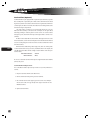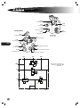
1
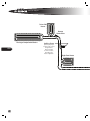
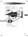
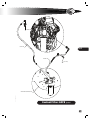
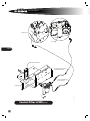
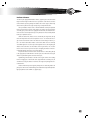
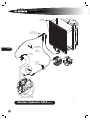
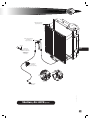
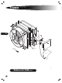
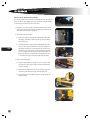
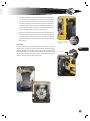
C oo l i n g S y s t e m
Overview
Coolant is circulated through the closed presurized system by the engine’s water pump whenever the engine is running. When the engine is cold, coolant flow
through the radiator is blocked by a conventional thermostat mounted at the engine
coolant outlet. The closed thermostat causes the coolant to be directed through a
bypass integral to the engine block when the engine is cold.
As the engine warms, heat is transferred to the coolant and the thermostat gradually opens the radiator circuit while increasingly obstructing the bypass. Coolant
from the engine”s coolant outlet increasingly enters the radiator at the top, passes
through the radiator’s coils and leaves the radiator at the bottom on its way back to
the engine coolant inlet. When the engine has reached full normal operating temperatature, the thermostat is fully open, the bypass path is closed, and all coolant
circulates through the radiator.
During normal running, engine cooling is regulated by controling the effectiveness of the radiator. This is accomplished by powering and de-powering the fan
which draws ambient air over the coils of the radiator. On Forward Engine All Americans, the fan is mounted to an electromagnetic fan clutch assembly mounted to the
front of the engine and driven by the fan belt. The engagement and disengagement
of the fan clutch is controlled by the engine ECM. The electrically-controlled fan
clutch of the All American Forward Engine is described in the electrical chapter.
On Rear Engine All Americans, the fan is driven by a remotely mounted hydraulic
motor. Unlike the single-speed on/off cycling of the fan on Forward Engine All-American’s, the speed of the fan on Rear Engine units is variable, and runs faster or slower
as controlled by temperature sensors. The hydraulic fan motor of the All American
Rear Engine is described in the Hydraulic System chapter.
On buses operated in colder climates, the radiator may be fitted with optional
Radiator Shutters, a vane-like assembly which serves to block air from passing over
the radiator coils. This prevents over-cooling and aids warm-up of the coolant so that
interior heaters become effective sooner. The Radiator Shutters may be either hydraulically controlled (powered by engine oil pressure), or pneumatically controlled
(powered by air pressure from the supply tank of units with air brakes or air suspension).
The cooling system components are plumbed using either standard black rubber
hoses or optional hoses which are blue in color and typically have longer life.
The bus may be fitted with an optional Perry Coolant Filter, which is attached to
the engine water jacket at two loctions, creating an alternate “side path” for coolant
to flow. The filter traps contaminates as coolant circulates through the replaceable
filter.
Engine coolant also circulates through a separate transmission cooler. Unike the
coolant filter, this poriton of the coolant’s flowpath is not a parallel “alternate path”
of the cooant flow. Once the engine has reached normal operating temperature and
the thermostat has fully opened, all the coolant passes through the transmission
cooler, “in series” with the radiator. The inlet side of the transmission cooler receives
coolant that has already passed through the radiator. Inside the transmission cooler,
the water circulates around a coil through which transmission fluid circulates. At
651
L
service manual
652
L
normal operating temperatures, the engine coolant is signifciantly cooler than the
the transmission fluid and thereby serves to cool the transmission fluid. In extremely
cold climates, during engine warm-up, the warming engine coolant helps bring the
transmission fluid up to sufficient temperature for the transmission to operate.
Heated engine coolant also provides the heat for the bus’s interior heating units.
The heater plumbing circuit is a “parallel” circuit which begins at the high pressure
side of the engine water jacket, cycles through the various heater elements and returns by way of an inlet to the transmission cooler. There it rejoins the coolant bath
circulating through the transmission cooler, and thereby finds its way back to the
engine inlet. A cut-off valve is provided at engine heater outlet pipe and at the transmission cooler’s heater circuit inlet. This allows the heating circuit to be blocked at
both ends when servicing the cooling system or when it is desireable to prevent
heaters from warming up during summer months.
The heater supply tubing from the engine leads to the Driver’s remote heater
valve, an electrically-controlled valve which enables the Driver to control the effectiveness of all heaters by regulating the amount of engine coolant circulating
through the heater circuit.
Depending upon the heaters configuration, the heater circuit may be equipped
with an optional auxilliary water pump to help force-circulate coolant through the
heaters. The auxilliary pump on Forward Engine All Americans resides in a dedicated
housing mounted to the floor along the heater piping. On Rear Engine All Americans,
the auxilliary water pump is mounted forward of the radiator and is accessible from
under the rear overhang. The inlet side of the auxilliary pump receives coolant from
the high pressure side of the engine water jacket. The outlet side leads to the series
of heaters and then returns via the transmission cooler as described above. Thus, the
transmission cooler receives coolant that has cooled by transferring its heat to the
heaters and/or by passage through the radiator.
The cooling filler neck is connected to a deaeration tank located at the highest
point of the cooling system flow circuits. Tubes lead to the deaeration tank from the
tops of the radiator, the engine, and the transmission cooler. This provides a path for
air bubbles in the circuits to rise to the deaeration tank. When pressure inside the system rises sufficiently to overcome the spring of the filler neck’s pressure cap, air that
has collected in the top of the deaeration tank escapes, reducing the system pressure
to normal. A sight glass is provided on the deaeration tank to inspect coolant level.
Coolant level should be maintained at just above the sight glass (the glass is full).
On Forward Engine All American’s the radiator must be removed to gain access
to certain service components on the front of the engine. To facilitate this, an option
popularly installed on Forward Engine buses is a swing out radiator, which provides
limited access without requiring draining of the coolant.
The three main symptoms of trouble in the cooling system are overheating,
overcooling, and loss of coolant. A cooling system should first be diagnosed by a
thorough visual inspection. Debris accumulation in the radiator fins or bent fins restricting airflow can cause overheating. If visual inspection reveals no cause, tools
and test equipment will be needed to proceed.
Forward Engine heater supply cutoff valve. Accessible from
interior engine compartment hood.
Forward Engine heater return cutoff valve. Accessible from
under the bus, forward of the entrance stepwell.
Rear Engine (Cat C7 shown) heater supply cutoff valve.
Accessible from engine compartment.
Rear Engine heater return cutoff valve. Accessible from under
the bus, forward of the radiator.
cooling
When excessively high operating temperature is observed, first check for proper
fluid level at the sight glass of the deaeration tank. If the fluid level is low and cannot
be maintained without constant refill, inspect for leaks at pipe and hose connections.
Also look for damaged hoses due to heat or chaffing from incorrect routing. Remember that the heater system is a potential area for leaks. The heating system can be
isolated by closing the gate valves at the engine’s heater outlet and the transmission
cooler’s inlet.
In the case of overheating, the next step is to verify the proper operation of the
thermostats. Refer to the appropriate engine manufacturer’s service publication for
instructions on the removal and testing of the thermostats.
[Warning] The engine, coolant, and transmission fluid may be very hot
(possibly above the boiling point at atmospheric pressure). Allow the system to
cool completely before working on it. Engine coolant use and disposal is governed by environmental regulations. Read carefully and abide by the warnings
and guidelines on the coolant label.
653
L
service manual
%SJWFS4JEF
)FBUFS
3FNPUF
)FBUFS7BMWF
1BTTFOHFS$PNQBSUNFOU)FBUFST
654
"VYJMJBSZ1VNQ
0QUJPOBMQVNQIFMQT
DJSDVMBUFFOHJOFDPPMBOU
UISPVHIIFBUFST
.BZCFJOTUBMMFE
BUWBSJPVTMPDBUJPOT
EFQFOEJOHVQPO
IFBUFSDPOmHVSBUJPO
3JHIU'SPOU)FBUFS
L
cooling
$PPMBOU'JMUFS
0QUJPOBMmMUFSVOJUNPVOUFEJO
BOBMUFSOBUFQBSBMMFMQBUIGPS
DPPMBOUUPnPX4IVUPõWBMWFT
QSPWJEFEUPJTPMBUFUIFmMUFS
GPSFMFNFOUDIBOHF
'BO$MVUDI.PUPS
JTDPOUSPMMFECZ
UIFFOHJOF&$.
0O"'&FMFDUSPNBHOFUJD'BO$MVUDI
DZDMFTPOBOEPõ
0O"3&IZESBVMJDNPUPSWBSJFTJOTQFFE
4IVUUFST
PQFOBOEDMPTF
BDDPSEJOHUPUFNQFSBUVSF
NFBTVSFEBU
CPUIUIFXBUFSKBDLFU
BOEUIFJOUBLFBJS
655
5SBOTNJTTJPO$PPMFS
"BDPJMUISPVHIXIJDI
USBOTNJTTJPOnVJEDJSDVMBUFTJTCBUIFE
JOFOHJOFDPPMBOUUPDBSSZBXBZIFBU
"MTPTFSWFTBTUIFSFUVSOQPJOUPGDPPMBOU
DJSDVMBUJOHUISPVHIIFBUFST
)FBUFS
$VU0õ7BMWFT
L
service manual
INSTALL ITEM 121 TO THE UNDERSIDE OF THE
HOOD LEDGE TO PREVENT HOSE (ITEM 104)
FROM RUBBING ON THE STRUCTURE.
TO UPPER PORT
ON RADIATOR
TO LOWER PORT
ON RADIATOR
656
SWINGOUT RADIATOR
TO ENGINE
WATER OUTLET
TO AIR INTAKE
ELBOW ON LEFT
SIDE OF ENGINE
TO TURBO
COMPRESSOR
OUTLET
L
Cooling System: A3FE With Cat C7-07
cooling
NOTE: INSTALL TEFLON TAPE ON ALL THREADS ON PARTS
THAT ARE INSTALLED IN THE SURGE TANK.
USE PIPE SEALANT ON ALL OTHER PIPE THREADS.
110
SURGE TANK MOUNTING BRACKET IS A
SUBPART TO THE FRONT STRUCTURE.
1.88±.06
CUT LINE
SCRAP
DETAIL "A"
TO
ENGINE
VENT
657
TO ENGINE
WATER INLET
NOTE: COOLANT RECOVERY TANK MOUNTS
IN FRONT OF RIGHT HAND OUTRIGGER.
TRANSMISSION
COOLER ASSY.
0115881c
BOLTS TO LOWER
INSIDE OF RH DROP RAIL.
L
service manual
INSTALL ITEM 121 TO THE UNDERSIDE OF THE
HOOD LEDGE TO PREVENT HOSE (ITEM 104)
FROM RUBBING ON THE STRUCTURE.
TO UPPER PORT
ON RADIATOR
TO LOWER PORT
ON RADIATOR
658
SWINGOUT RADIATOR
TO AIR INTAKE
ELBOW ON LEFT
SIDE OF ENGINE
TO ENGINE
WATER OUTLET
TO TURBO
COMPRESSOR
OUTLET
Cooling System: A3FE Cummins ISB-07 Hi Torq
L
cooling
NOTE: INSTALL TEFLON TAPE ON ALL THREADS ON PARTS
THAT ARE INSTALLED IN THE SURGE TANK .
USE PIPE SEALANT ON ALL OTHER PIPE THREADS.
1.88±.06
CUT LINE
SURGE TANK MOUNTING BRACKET IS A
SUBPART TO THE FRONT STRUCTURE.
SCRAP
DETAIL "A"
USE FASTENERS SUPPLIED WITH FAN
CLUTCH. TORQUE TO 20-25 FT/LBS.
659
TO
ENGINE
VENT
TO 3/4 PORT ON WATER INLET.
NOTE: COOLANT RECOVERY TANK MOUNTS IN FRONT
OF RIGHT HAND OUTRIGGER. ALSO ITEM 12
IS NOT VISIBLE.
TRANSMISSION
COOLER ASSY.
0112287d
TO ENGINE
WATER INLET
L
service manual
INSTALL ITEM 121 TO THE UNDERSIDE OF THE
HOOD LEDGE TO PREVENT HOSE (ITEM 104)
FROM RUBBING ON THE STRUCTURE.
TO UPPER PORT
ON RADIATOR
TO LOWER PORT
ON RADIATOR
660
SWINGOUT RADIATOR
TO AIR INTAKE
ELBOW ON LEFT
SIDE OF ENGINE
TO ENGINE
WATER OUTLET
TO TURBO
COMPRESSOR
OUTLET
Cooling System: A3FE Cummins ISB-07 Lo Torq
L
cooling
NOTE: INSTALL TEFLON TAPE ON ALL THREADS ON PARTS
THAT ARE INSTALLED IN THE SURGE TANK.
USE PIPE SEALANT ON ALL OTHER PIPE THREADS.
1.88±.06
CUT LINE
SURGE TANK MOUNTING BRACKET IS A
SUBPART TO THE FRONT STRUCTURE.
SCRAP
DETAIL "A"
USE FASTENERS SUPPLIED WITH FAN
CLUTCH. TORQUE TO 20-25 FT/LBS.
661
TO ENGINE
VENT
TO 3/4 PORT ON WATER INLET.
NOTE: COOLANT RECOVERY TANK MOUNTS IN FRONT
OF RIGHT HAND OUTRIGGER. ALSO ITEM 12
NOT VISIBLE.
0108487g
TO ENGINE
WATER INLET
L
service manual
ITEM NO.
33 AND 44
37
49
14 & 15
TORQUE VALUE
80 - 90 FT LBS
29 - 33 FT LBS
8 - 9 FT LBS
60 IN LBS
SHOULD HAVE A
CONTINUOUS DOWNWARD SLOPE TO
THEIR CONNECTION.
TO RADIATOR
THERMOSTAT HOUSING
PLACE STRAIGHT SEAL PRIOR
TO MOUNTING
TO THERMOSTAT HOUSING
ON ENGINE
662
PLACE RUBBER SEAL ON VERTICAL
SECTION OF SHROUD ONLY PRIOR TO
PLACEMENT ON RADIATOR.
APPLY RUBBER SEAL TO ALL CLOSEOUT
BAFFLE EDGES PRIOR TO PLACING ON BODY.
15
33
33
49
44
UTILIZE GIVEN HARDWARE IN
ASSY 0112437
4- CAPSCREWS 1/2-13 X 1.50
4- NUT HEX HD 1/2-13 LOCKING
8-WASHERS FLAT, .531X2.250X11GA,YDICH
37
37
37
44
UNUSED HOLES OMMITED
FOR CLARITY
37
Cooling System: A3RE With Cat C7-07
L
cooling
TO MTG BRACKET STABILIZER
33
33
14
14
44
NOTE:
HUCK BOLT SUPPLIED WITH
SUBFRAME ATTACHING
15
15
44
663
TO ENGINE INTAKE
TO LOWER RADIATOR
CONNECTION.
NOTE: FOR RETARDER
OPTION ONLY.
14
14
PLUG W/OUT RETARDER
TO WATER PUMP INLET
0120962a
TO THERMOSTAT HOUSING
L
service manual
SHOULD HAVE A
CONTINUOUS DOWNWARD SLOPE TO
THEIR CONNECTION.
TO RADIATOR (39")
TO TURBO (18")
ISC ONLY
TO ALTERNATOR
BRACKET
ISC ENGINE ONLY
TO THERMOSTAT
HOUSING
ON ENGINE
PLACE STRAIGHT SEAL PRIOR
TO MOUNTING
TO EGR COOLER
(7.5" ISC) (24" ISB)
664
PLACE RUBBER SEAL ON
VERTICAL SECTION OF
SHROUD ONLY PRIOR TO
PLACEMENT ON RADIATOR.
APPLY RUBBER SEALTO ALL CLOSEOUT
BAFFLE EDGES PRIOR TO PLACING ON BODY.
14
FOR COOLANT
OVERFLOW HOSE
15
14
33
33
49
44
37
UTILIZE GIVEN HARDWARE IN
ASSY 0112437
4- CAPSCREWS 1/2-13 X 1.50
4- NUT HEX HD 1/2-13 LOCKING
8-WASHERS FLAT, .531X2.250X11GA,YDICH
37
ITEM NO.
33 AND 44
37
49
58 ISB
58 ISC
37
44
TORQUE VALUE
80 - 90 FT / LBS
29 - 33 FT / LBS
8 - 9 FT / LBS
22 - 25 FT / LBS
53 - 58 FT / LBS
UNUSED HOLES OMMITED
FOR CLARITY
37
Cooling System: A3RE Cummins ISC-07 & ISB-07
L
cooling
33
14
33
TO TURBO
14
44
15
14
44
665
HEATER PLUMBING
ISC AND ISB
15
RETARDER OPTION
ISC ONLY
NOTE:
ISB HUMP HOSE ONLY
15
CONNECTION TO UPPER INTAKE
TO THERMOSTAT BYPASS HOSE
LOCATED ON ENGINE.
TO RADIATOR OUTLET
TO RADIATOR INLET
TRANS OIL COOLER
PLUG W/OUT RETARDER
TO ENGINE WATER OUTLET
ISC INSTALL ONLY
NOTE: CONNECTION TO WATER
OUTLET ON ISB07 ONLY
TO WATER PUMP INLET
37
58
37
NOTE:
MOUNTS TO FRONT FACE OF THE
CYLINDER HEAD ON ISC ONLY
NOTE: MOUNTS TO THE TOP OF THE
ALTERNATOR BRACKET ON ISB ONLY.
WATER PUMP INLET
ISB ONLY
0111827l
58
L
service manual
666
L
cooling
To Radiator Side Tank
At Elbow Item #41
To Upper Radiator
Tube Elbow
To Thermostat
Housing
On Engine
0013128y
667
Cooling System: A3RE With John Deere 8.1
L
service manual
About Coolant
668
As emission and performance regulations become more stringent, the normal operation temerature range for turbocharged diesel engines increases. One of the consequences is that careful maintenance of the cooling system becomes increasingly
critical in prolonging the life of the engine. At higher temperatures, relatively minor
imbalances or impurities in the coolant can dramatially increase the potential for
corrosion. Establish a disciplined and consistent regimine for monitoring and testing
the coolant in your Blue Bird school buses. Keep accurate records, use only coolants
recommended by the engine manufacturer. Change coolant within its specification
lifetime and never mix different types of coolant.
Periodic testing and maintenance of the coolant should be performed in accordance to the engine manufacturer’s specifications. Testing and maintenance procecures differ between standard-life and extended-life coolants. Locally available test
strips may be used to test standard-life coolants. However, such test strips are not
appropriate for long-life coolants; therefore long-life or extended-life coolants must
be sample tested at qualified cooant laboratories. Because specification, recommendation, and terminologies differ among engine manufacturers, Blue Bird advises stictly adhering to the coolant maintenance specifications of the engine manufacturer.
Carefully following the engine manufacturer’s recommendations is the surest way to
maintain compliance with engine warranties.
Beginning in January of 2007, Blue Bird implemented a program to simplify the
coolant types installed at the factory.
Standard Equipment Coolant
John Deere Cool-Gard 50/50 premix (green in color) is installed as standard equipment across all the above listed bus products powered by Caterpillar, Cummins, or
John Deere engines.
This coolant meets John Deere’s specifications and requirements for extendedlife coolant. It is to be considered standard-life coolant when installed in Caterpillar
or Cummins engines..
Optional Extended Life Coolant
Two optional coolants are offered as extended-life coolants for the above listed bus
models when not powered by John Deere engines.
Extended Life Coolant for Caterpillar Engines
Caterpillar ELC 50/50 premix (red in color) is installed in the above listed bus products
equipped with Caterpillar engines when purchased with an option for extended-life
coolant.
Extended Life Coolant for Cummins Engines
Fleetguard ES Optimax 60/40 premix (red in color) is installed in the above listed
bus products equipped with Cummins engines when purchased with an option for
extended-life coolant.
L
cooling
Coolant Filter
On all of the above-listed bus models equipped with an optional coolant filter, the
same Wix replacement filter element cartridge is used:
Blue Bird Part Number: 0064641
Wix Part Number: 24070
The coolant filter should be replaced every 6 months or 6,000 miles; whichever occurs first.
Coolant Decals
On all of the above-listed bus models, Blue Bird installs a decal stating:
• The type of coolant installed at the factory.
• The coolant manufacturer’s part number for one gallon quantity, suitable for
regular top-off and refill.
• The coolant manufacturer’s part number for one gallon quantity of the concentrate version of the installed coolant, suitable for formulating stronger glycol mixture ratio.
Blue Bird also installs a second decal containing radiator warnings. Both decals
are mounted near the coolant fill neck.
669
Coolant Maintenance
Blue Bird advises strictly abiding by the following policy for all coolant maintenance
for the life of the vehicle.
Never Mix Coolant Types
Routine coolant addition (top-off) must match the installed coolant type and brand.
Do not mix coolants of different colors, types, or brands in the same engine.
Strictly Follow The Engine Manufacturer’s Specifications
Each engine manufacturer publishes its own specific requirements for testing and
maintaining coolant in their respective engines. Blue Bird recommends strictly abiding by the engine manufacturer’s testing and maintenance schedules and draining,
flushing, refilling procedures to maintain compliance with the engine warranty requirements. Blue Bird recommends that you maintain accurate vehicle-specific service records of all coolant system maintenance procedures performed.
For Caterpillar or Cummins engines equipped with John Deere Cool-Gard coolant, follow the engine manufacturer’s maintenance schedules for standard-life coolant, not for extended-life coolant.
For Caterpillar engines using Caterpillar ELC extended life coolant, perform testing at a qualified coolant laboratory per the Caterpillar Operation and Maintenance
Manual. Label sample as Extended-Life coolant.
Coolant test kits are locally avaliable. The red dye commonly
used in extended-life coolants may cause erroneous
readings of test strips. Always follow engine manufacturer’s
recommendations for coolant; and coolant manufacturer’s
recommendations and specifications for testing.
L
service manual
For Cummins engines using Fleetguard ES Optimax extended-life coolant, send
coolant samples to Fleetguard for Monitor C testing, as specified in the Cummins
Operator’s Manual. Label sample as Extended-Life coolant.
For Caterpillar, Cummins, or John Deere engines using John Deere Cool-Gard
coolant, send coolant samples to a John Deere lab for Cool Scan testing; or test manually using a John Deere Three-Way test strip, supplied in John Deere 3-Way Heavy
Duty Coolant Test Kit TY6175.
Always Mix Concentrate With Premix Coolant, Not Water
If concentrated coolant is added in order to raise the glycol ratio, use only the concentrate version of the same premix coolant type and brand as installed. Do not mix
the concentrate with water. Instead, mix the concentrate with the premix version of
the same coolant.
670
L
Only Add Tap Water In Emergency Situations
A regularly-scheduled bus inspection and maintenance program should be followed
to prevent coolant losses due to damaged or worn hoses, loose clamps, etc.
If coolant is lost while the bus is in use, and roadside emergency measures are
called for, replenish the coolant with the same premix type and brand if possible.
If the proper coolant is not available, and water must be used, use only de-ionized
water if possible. Ordinary tap water should only be used if proper coolant or de-ionized water are not available.
Whenever tap water alone has been added, the bus should be taken to a service
facility and the entire cooling system should be completely drained, flushed, and
refilled with premix coolant.
cooling
FACTORY INSTALLED COOLANTS
John Deere Cool-Gard
Green in color. Standard equipment coolant in all A3FE, A3RE, BBCV, BCCV.
Qualifies as extended-life coolant in John Deere engines.
Considered standard-life coolant in Caterpillar and Cummins engines.
Concentrate version may be mixed with the pre-mix version to lower freezing point.
50/50 Premix
1 Gallon Container
blue bird number
john deere number
0109179
TY25081
2 1/2 Gallon Container
TY16036
55 Gallon Drum
TY16037
330 Gallon Tote
TY24504
Concentrate
1 Gallon Container
TY16034
Caterpillar ELC
Red in color. Optional coolant in A3FE, A3RE, BBCV, BCCV with Caterpillar engines.
671
Qualifies as extended-life coolant in Caterpillar engines.
Blue Bird installs 50/50 premix, which is available in one gallon and larger (listed) containers.
The 50/50 premix may be mixed with the concentrate version per Caterpillar’s instructions to achieve 60/40 ratio.
Concentrate version may be mixed with the pre-mix version to lower freezing point.
50/50 Premix
blue bird number
1 Gallon Container
Case of six 1 Gallon Containers
caterpillar number
101-2844
0113986
55 Gallon Drum
101-2845
275 Gallon Tote
222-1534
Concentrate
1 Gallon Container
0113987
119-9150
Fleetguard ES Optimax
Red in color. Optional coolant in A3FE, A3RE, BBCV, BCCV with Cummins engines.
Qualifies as extended-life coolant in Cummins engines.
Blue Bird installs 60/40 premix, which is not available in one gallon containers, but is available in larger containers (listed).
The 50/50 premix may be mixed with the concentrate version per Fleetguard’s instructions to achieve 60/40 ratio.
Concentrate version may be mixed with the pre-mix version to lower freezing point.
50/50 Premix
1 Gallon Container
blue bird number
fleetguard number
0109178
CC2785/2785X
60/40 Premix
55 Gallon Drum
CC2770/2770X
275 Gallon Tote
CC2790/2790X
Concentrate
1 Gallon Container
0109552
CC2780/2780X
L
service manual
Coolant Filter (Optional)
672
Your Blue Bird bus may be equipped with an optional Perry Coolant Filter, a separate
filter assembly with a replaceable spin-on filter element. On All American Forward
Engine buses, the filter is mounted to the left side of the engine block. On All American Rear Engine, the filter is mounted to the radiator brace mounting bracket at the
left side of the engine compartment.
The entire volume of coolant does not pass through the filter on each cycle.
Rather, the filter assembly is connected to two coolant ports on the engine block,
effectively providing an “alternate path” for coolant to flow. As coolant circulates
through the system, that volume which passes through the filter is cleaned of contaminates.
The filter mount is fitted with two shut-off valves. Closing both valves closes the
inlet and outlet lines, to allow removal and replacement of the filter element without
excessive coolant spillage. The amount of coolant lost is that contained in the volume
of the filter element.
All American buses built during or after August, 2006, have one of three specific
coolants installed at the factory (see Factory Installed Coolants in this chapter.) The
same Wix replacement filter element cartridge is used for all three of the factory installed coolants:
Blue Bird Part Number:
0064641
Wix Part Number:
24070.
Do not use coolant filter elements which dispense Supplemental Coolant Additives
(SCAs) to the system.
Coolant Filter Element Replacement
The coolant filter should be replaced every 6 months or 6,000 miles; whichever occurs first.
1. Fully close both shut-off valves at the filter mount.
2. Remove the filter element by turning it counter-clockwise.
3. Fill a new filter element of the proper type for the coolant in use withi premixed coolant of the same type already in the engine. Install the new and
filled filter element.
4. Open both shut-off valves.
L
cooling
SUPPLY LINE
673
RETURN LINE
(18-22 LB-FT)
0116955c
RIGHT HAND FRONT DROP RAIL
Coolant Filter: A3FE
Optional
L
service manual
FLYWHEEL HOUSING
OIL FILTER
674
RADIATOR MOUNTING BRACE
RETURN- FROM FILTER OUTLET TO
ENGINE WATER PUMP INLET.
SUPPLY-FROM ENGINE-REAR
TO FILTER TOP/INLET.
Coolant Filter: A3RE Optional
L
0121317b
LH SUBFRAME
cooling
Radiator Shutters
Your bus may be equipped with Radiator Shutters, a popular option on both Forward
Engine and Rear Engine All American buses operated in colder climates. Shutters
restrict ambient air passing through the radiator and over the engine, and thereby
shorten warm-up time for the engine and passenger compartment heaters.
The Kysor Radiator Shutters unit is a window blind-like assembly of adjustable
leuvers mounted on the fan-side of the radiator. The shutters are spring-loaded in
a normally-open position. On buses equipped with air brakes, the shutter mechanism is closed at certain temperatures by an air cylinder, and on buses with hydraulic
brakes, by an hydraulic actuator.
Unlike the radiator fan, shutters are not controlled by the engine ECU, but by
their own independent circuit. Two temperature sensors—one mounted in the engine coolant circuit and the other in the intake tract of the Charge Air Cooler system—are wired in the Radiator Shutters control circuit. Both sensors are normally
closed. When ignition is on, current passes through both sensors, and energizing the
Shutter control solenoid to close the shutters. As the engine warms, one or both of
the two sensors create an open in the circuit, de-energizing the shutter control solenoid and allowing the leuver vanes to open the shutters.
Air-powered shutter solenoids receive actuation air from a line leading directly
to the supply (wet) air tank. When the solenoid opens, the air which was closing the
shutters is expelled through the solenoid’s exhaust port.
Hydraulically-powered shutter solenoids receive engine oil from a line leading
from an oil supply port on the left side of the engine. When the solenoid opens, the
oil which was closing the shutters is returned to the engine sump through the solenoid’s drain line.
Shutters should be inspected regularly and kept free of obstructing debris. The
pivot points of the leuvers and their linkages should be lubricated periodically with a
light spray lubricant such as WD40 or a graphite spray.
675
L
service manual
Lubricate
upper and lower
pivot points and track.
IN
T
OU
DRAIN
Shutter solenoid
mounted to lower left side of
Engine closeout panel.
(ISB only)
Cummins ISB:
Install on Left side
of air intake manifold elbow.
676
Cat C7:
Install in port
On left Intake Elbow.
To oil supply port
onleft side of engine.
Thermostat
Housing
Mounts to
threaded boss
just above
oil pan flange
Turbo Side
Of Valve Cover
Cummins ISB
Cat C7
Cat C7 Only
Viewed from the left side of the engine.
Shutters, Hydraulic: A3FE Optional
L
0002013r
Cummins
ISB
cooling
Lubricate upper and lower
pivot points and track.
Shutter solenoid mounted to
lower left side of
engine closeout panel.
IN
T
OU
(ISB only)
677
Cummins ISB:
Install on left side of
air intake manifold elbow.
Cummins ISC & Cat:
Install inport on
left CAC tube.
Mount bracket to
threaded boss
just above oil pan flange.
Thermostat
Housing
Turbo Side
Of Valve Cover
Cummins ISB
Cummins ISC
Cat C7
Shutters, Air: A3FE Optional
0002015h
To Accessory Port
at Wet Tank
L
service manual
678
To 1/2-14 port
on upper radiator tube
Lubricate
pivot points and tracks
on shutter.
Shutters, Air: A3RE Optional
L
0006617e
Wet Tank
cooling
Radiator
On both All American Forward Engine and All American Rear Engine buses, the radiator is pre-assembled to a similarly-constructed Charge AIr Cooler; however, other
than being assembled and mounted as a combined “cooling pack”, the two units
serve two separate circuits and do not directly interact. While the radiator serves
to remove heat from the circulating engine coolant, the Charge Air Cooler removes
heat from the engine intake air. Both perform their functions by passing ambient air
drawn by the radiator fan across tubing coils which contain coolant (in the radiator)
or filtered intake air (in the Charge Air Cooler). The thin corregated fins of each unit
conduct heat from the internal coils and thereby disperses it across a broad surface
area, allowing it to be carried away by the flow of air.
See the Intake chapter for a more complete functional description of the Charge
Air Cooler system. In the descriptions below, references to “the radiator assembly” refer to the combined cooling pack, since the radiator and CAC are handled as a unit. If
the bus is equipped with optional radiator shutters, the shutters unit is also attached
to the radiator, and all three components are removed and installed together.
Swing Out Radiator
On Forward Engine All Americans, servicing components at the front of the engine
and behind the radiator assembly, such as pulleys, water pump, fan belt, fan clutch,
air conditioner compressors, or radiator shutters may require removal of the radiator.
A popular option on Forward Engine units, therefore, is a special set of parts which
allow the radiator to be pivoted slightly without disconnecting coolant hoses and
draining coolant.
The actual mounting of the radiator unit itself is very similar between the standard installation and that of the swing out radiator option. The components which
differ are:
• Longer coolant hoses to allow the necessary flexibility at the right side of the
radiator.
• The fan shroud flange is fitted with a release clasp to provide clearance from
the fan blades when the radiator is pivoted.
• A set of slotted bumper brackets which allow the bumper to pivot downward
without complete removal.
679
L
service manual
Radiator Removal, All American Forward Engine
The following radiator removal procedure is illustrated with a bus which has the
swing-out radiator option. Differences between this and the standard installation
are noted in the procedure text. To remove the radiator:
1. Completely secure the bus against accidental movement. Remove the ignition key. Chock all wheels. Disconnect the positive battery terminals (or turn
off the master power switch if so equipped.)
Rock guard plate
2. Pivot or remove the front bumper:
2.1 Remove the stepwell rock guard plate bolted between the bottom
right flange of the bumper and the forward edge of the stepwell. (5
bolts, washers, nuts).
2.2 Look inside the bumber openings at the mounting brackets just above
the tow hooks. If the top bracket bolt is mounted in a curved slot of
the brackets, the bumper is a pivoting bumper. On each side, loosen
the bolt in the curved slot. Then loosen the bottom bolts. If the brackets are not slotted, remove the four bolts completely and remove the
bumper. (Tip: If the bus is equipped with a pivoting bumper, it serves
as an effective “parts tray” for fasteners throughout the procedure.”
680
Sloted bracket on pivoting bumper
Two bolts pers side for bumper pivoting/removal
3. Remove the front grille panel:
3.1 Open the hinged grille panel. Spread one closed end of the S-hook
at the upper end of the support cable to unlatch it from the bracket.
Then close the panel.
3.2 Remove the four phillips screws (two on each side) between the slots
of the lower portion (below the hinge) of the front grille panel.
3.3 Open the hinged panel. Carefully lift the grille assembly upward and
away from the bus.
Pivoting bumper
Four grille mounting screws
Grille removed.
L
cooling
4. Remove the cross bar which spans the radiator opening near the bottom of
the radiator. (Four bolts, washers, lockwashers, and nuts.)
5. Inside the bus, remove the engine cover and housing:
5.1 Open the hinged cover. Remove the bolt, lockwasher, and nut which
secures the bottom end of the support cable.
5.2 Unlatch the five clasp latches which secure the cover housing.
5.3 Being careful to separate the rubber gasket from the opening surrounding without damaging it, lift out and remove the whole engine
cover assembly.
6. Loosen CAC tubes: Loosen the rearmost clamp of the red flex tube which
connects the left CAC pipe to the engine intake elbow. Similarly loosen the
rearmost clamp of the right-side CAC pipe. Push forward on the flex tubes to
make sure they are unstuck and can slip off when the radiator is removed.
Remove 4 bolts, washers, nuts from crossbar.
Open the hood.
681
Disconnect support cable.
Unlatch 5 clasps.
Close hood. Lift out as a unit.
Loosen CAC clamps.
L
service manual
7. If the radiator is not equipped with the pivot option, drain the coolant:
682
7.1 Position a clean receptacle under the petcock drain at the bottom of
the radiator. Remove the filler pressure cap. Open the petcock drain.
(Tip: After draining at the petcock stops, it is often helpful to also loosen the lower radiator hose clamp and insert a screwdriver between
the hose and the radiator. This allows additional coolant to drain from
the dip in the lower hose.)
Radiator drain petcock
7.2 Disconnect the radiator hoses: Loosen the deaeration vent hose clamp
at the top of the radiator and push the vent hose end off the radiator.
Loosen the upper and lower radiator hose clamps and push the hoses
back enough to ensure they are unstuck and will slip off when the
radiator is removed.
8. Remove the harness clamp bolts which secure the harness along the driver’s
side of the radiator.
Bottom radiator hose
11. If the bus is equipped with the pivot radiator feature, release the clasp at the
lower left of the fan shroud. This lets the shroud expand slightly to provide
needed clearance with the fan when the radiator hinges.
Disconnect radiator hoses after draining. Not necessary on
buses equipped with pivot radiator feature.
Remove the harness clamps from the radiator and push the
harness out of the way.
(Viewed from under the radiator.) On buses with pivoting
radiators, a clasp on the right side of the fan shroud allows it
to expand to provide clearance from the fan blades when the
radiator is pvioted.
L
cooling
12. The radiator assembly is mounted on four rubber-cushioned mounts, two
on each side. If the bus is equipped with the pivot feature, remove only the
fasteners on the driver side, and only loosen the fasteners on the curbside.
These will serve as hinges when loosened. Pull outward on the driver side of
the radiator to hinge it outward. Ensure that the Driver-side CAC tube does
not snag. Hinge the radiator far enough to insert the hold-open rod mounted above the radiator into the hole in the top of the radiator.
13. If the bus is not equipped with the radiator pivot feature, completely remove
all four mounting bolts, eight washers, and four nuts. With an assistant, lift
the radiator forward and away from the bus. As the radiator is pulled out,
support the CAC pipes with one hand, with the other hand under the bottom
of the radiator.
Reassembly
Having the radiator removed or hinged provides access to engine front components.
After the service procedures are complete, reinstall the radiator, bumper, rock guard,
CAC tubes and grille in reverse order of the removal proceure outline. If the coolant
has been drained into a clean recepticle, and if it is still within its service life, it may be
reinstalled. After refilling, bleed the heater system to remove trapped air and ensure
that the coolant level is topped-off to the proper level.
Loosen all four radiator mount bolts. On
pivoting radiators, remove only the driver
side two. On non-pivoting radiators,
remove all four.
683
Radiator hold-open rod
Pivoted radiator provides engine front access without draining
coolant.
Obtain assistance in lifting out
non-pivoting radiator.
L
service manual
Cooling System Drain, Flush & Refill
The following is a general procedure for complete coolant change (drain, flush, refill). Blue Bird recommends that an authorized Caterpillar, Cummins, and John Deere
dealer/distributor perform this flush and fill in their respective engines. If there are
differences between the information in this procedure and the engine manufacturer’s
Operator’s or Maintenance Manuals, follow the engine manufacturer’s instruction.
1. Drain the cooling system:
1.1 Park bus on a level surface, apply parking brake, turn off engine, remove ignition key and chock wheels.
1.2 Allow the engine to cool. Then remove the radiator cap. Locate and
open both heater hose cut-off valves. Open all heater control valves
fully. Removal of the thermostat may assist in draining, flushing, rinsing and refilling process. Follow engine manufacturers’ recommendations on thermostat removal and installation.
684
L
[Warning] Coolant released under pressure can cause serious burns. Remove filler cap only when cool enough to touch with bare hands. Slowly loosen
cap to first stop to vent pressure before fully removing. Engine coolant is toxic
and is an eye and skin irritant. Protective gear should be worn when working
with coolant. Allow the system to cool before draining and flushing. Engine
coolant is a threat to the environment. Use suitable containers for disposal. All
applicable federal, state, and local laws must be observed when disposing of
engine coolant.
1.3 Place a drain pan under the radiator drain and open the drain petcock.
Drain and discard the coolant from the cooling system following all
applicable federal, state, and local laws governing disposal of engine
coolant. Be sure that all the heater valves are open in order to completely drain the engine, heaters, coolers, hose, etc.
1.4 After system has drained, disconnect both the pressure and return
heater hoses. Using a shop air hose set at a maximum of 15 PSI, blow
air into the heater hoses to blow the remaining coolant from the heater system.
1.5 Open the lowest coolant drain port or plug from the engine to drain
any remaining coolant from the engine.
1.6 Close all drains, reconnect heater hoses, and reinstall all plugs that
have been opened or removed.
1.7 If the system has a coolant filter, close the valves to the filter and remove the filter element.
1.8 On All American Forward Engine Only: If the system has any material collected on the cap, neck or deaeration tank, remove and replace
cooling
the radiator cap (1325430), brass neck (0033762), and plastic deaeration tank (0032865). If the system has discolored coolant, inspect the
cap, neck and deaeration tank for accumulation of foreign material or
staining. If stained, clean the components. If the stain cannot be removed, replace the components. If the coolant is not discolored, and
there is no accumulation on theses components, do not replace these
components.
1.9 Reconnect all hoses that were disconnected while replacing components. Check all hose connections and clamps.
1.10 If the thermostat has been removed in an earlier step, reinstall thermostats following engine manufacturer’s procedures.
2. Clean the Cooling System. Follow the engine manufacturer’s instructions for
chemically cleaning the entire cooling system.
On Caterpillar engines: If sludge or oil is evident,, use Caterpillar’s 30-Day
cleaner. For scale or deposits, use Caterpillar “Quick Flush” type cleaner.
685
On Cummins engines: If sludge or oil is evident, Use Fleetguard Restore. For
scale or heavy metal deposits, use Fleetguard Restore Plus (+).
2.1 After the engine has been stopped and the cooling system has cooled,
drain the cleaner from the entire system following the steps describe
in the initial drain including blowing the system with 15 PSI (max) of
shop air.
2.2 Close all drains and reconnect all hoses that have been removed.
2.3 Fill the system with fresh water and run for minimum of 30 minutes on
high idle with heater pumps on and all heater valves open.
2.4 After the 30 minute (minimum) run, stop the engine and allow it to
cool. Then drain the water from the entire system following the steps
describe in the initial drain, including blowing the system with 15 PSI
(max) of shop air.
2.5 With the hoses disconnected and the drain valves open, run fresh
water through the heater system, radiator, transmission cooler and
engine until the water is clear.
2.6 Repeat steps 2.2 thru 2.5 as many times as required to ensure that the
system is clean and the chemicals are completely removed.
[caution] After having used cooling system cleaners, be sure the systems
are flushed 3–5 times to remove all cleaner from the system. If cleaner is not
completely removed, ammonia salts will be left from the cleaner and severe
copper corrosion can occur.
L
service manual
3. If the bus is equipped with an optional coolant filter, check the filter head,
clean filter head and lines as required to remove all of the old coolant and
any residue. Install a new coolant filter element.
686
L
4. Refill the cooling system with coolant recommended by the engine manufacturer. Read the About Coolant section of this chapter thoroughly for information about the coolants installed at the Blue Bird factory, and for Blue Bird
recommendations. Blue Bird recommends using only pre-mixed coolant, or
mixing of premixed coolant with concentrate of the same type and brand (as
opposed to mixing concentate with water) to raise the glycol ratio above that
of the premixed coolant. Blue Bird recommends always topping-off coolant
with the same pre-mixed coolant as is installed, rather than topping off with
water. If water is used for top-off, use only deionized water. Never add tap
water to the cooling system unless absolutely necessary in roadside emergency situations. Never mix coolants of different color, type, or brand. Keep
accurate records of all coolant changes and maintenance.
5. Bleed Air From the Cooling and Heater System:
5.1 Fully open the pressure-side heater hose cut-off valve. Fully close the
return-side heater cut-off valve (located near the transmission cooler).
5.2 In the Driver’s area, open all heater temperature controls to their full
on position, and turn on all heater pumps. The number of heater
controls, and the presence of heater pumps depends upon optional
equipment purchased on the bus.
5.3 With the engine stopped and a cool engine, remove the radiator cap.
5.4 On All American buses, locate the ¼” bleeder tube which is located
near the deaeration tank. The bleeder tube originates from a low point
of the cooling system, where the return heater hose returns coolant to
the transmission cooler; and runs to a location near the deaeration
tank.
On All American Forward Engine buses: Open the front grille panel.
The bleeder tube is tucked horizontally along the top of the radiator.
Pull out the bleeder hose and insert its free end into the open filler
neck of the deaeration tank. Then open the in-line bleed valve fully.
During bleeding, overflow coolant will be returned directly to the deaeration tank.
On All American Rear Engine buses: The bleeder tube is located underneath the deaeration tank and its end is already connected to the to
the tank. Open the in-line bleed valve fully. During bleeding, overflow
coolant will be returned directly to the deaeration tank.
cooling
5.5 Start engine and operate at 1800 to 2000 rpm. Watching the coolant
temperature gauge, ensure the engine reaches 180-190 degrees, the
temperature at which the engine’s thermostat normally fully opens.
5.6 Operate the engine with the bleeder valve open until all air has been
purged from the system. During this time, monitor the level of coolant in the deaeration tank sight glass. As air trapped in the system
escapes, the coolant level will occasionally rise and drop. Top-off the
coolant level with pre-mixed coolant whenever it drops below the full
level mark.
5.7 Air has been fully purged from the system when the coolant level no
longer fluctuates, and the stream of coolant from the bleeder hose is
constant. This may take 15-30 minutes.
5.8 After the air has been purged and solid stream is present, allow the
engine to return to idle to cool down gradually. Close the bleeder
valve and store the bleeder line in its original position.
5.9 Install the radiator cap.
5.10 Operate the engine until the thermostat opens. Then stop the engine
and let it cool for 15-30 minutes. Check the entire cooling and heating system for leaks. Recheck coolant levels and top off with the same
premixed coolant as is installed.
5.11 Obtain a coolant sample from the radiator drain petcock, and test
the glycol level with a refractometer to ensure the glycol level is 50%
minimum. If the glycol level is less than 50%, drain the appropriate
amount of coolant and add concentrate per the engine manufacturer’s instructions for increasing glycol percentage to correct level.
5.12 Pressure test the cooling system for leaks. If no leaks are found, the
bus may be returned to normal service.
687
L
service manual
Fan Clutch, All American Forward Engine
688
L
During normal running, engine temperature is regulated by controlling the cooling
effectiveness of the radiator. This is accomplished by powering and de-powering the
fan which draws ambient air over the coils of the radiator.
On All American Forward Engine buses, the fan is mounted to an electromagnetic clutch mechanism. The outer housing drum of the fan clutch is a pully driven by
the fan belt, and rotates whenever the engine is running. The fan blade assembly is
mounted to the inner rotor of the fan clutch. An electromagnetic mechanism within
the fan clutch assembly engages/disengages the inner rotor with the outer drum,
and also serves to “cushion” the initial shock of engagement.
The engagement and disengagement of the fan clutch is controlled by the engine ECU. The ECU electronically monitors a signal it receives from a temperature
sensor mounted near the engine coolant outlet. When the temperature signal reaches a pre-defined value, the ECU provides 12V current to engergize the fan clutch.
The clutch engages and the fan blades are driven at engine speed, drawing more air
through the radiator.
When the fan clutch is de-energized, the collapsing magnetic field momentarily
induces a current with reversed polarity in the stator. The electrical connector of the
fan clutch contains a diode which provides the induced current a low-resistance path
to ground, to protect other circuits from being affected.
cooling
Reinstallation
Reinstall in reverse order of the removal procedure, observing these requirements:
1. If the fan clutch assembly has been removed from the mounting bracket, be
sure to align the anti-rotation boss on the mounting side of the fan clutch
with the hole on the bracket:
2. Use these torque values when reassembling:
Journal Shaft to mounting bracket:
100 ft. lbs. (135 Nm.)
Fan mounting bolts to clutch hub:
25-28 ft. lbs. (34–38 Nm.)
Mounting bracket bolts to engine:
18-22 ft. lbs. (24–30 Nm.)
689
Be sure the anti-rotation boss
aligns with the hole in the
mounting bracket.
18-22 ft. lbs. (24-30 Nm)
25-28 ft. lbs. (34-38 Nm)
100 ft. lbs. (135 Nm)
L
service manual
Hydraulic Fan Drive, All American Rear Engine
690
L
The cooling system on an All American Rear Engine is similar to that of an All American Forward Engine in respect to coolant flow between the engine and the radiator.
Heat created by the engine will transfer to the coolant as the coolant flows through
the engine and then to the radiator. A fan is used to create air flow across the outer
surface of the radiator fins allowing the heat in the coolant to transfer into the moving air. This cycle of engine coolant absorbing heat from the engine and discharging
heat at the radiator is very similar for both products. The major difference between
the two products is how the fan creating the air flow across the radiator is driven.
The fan on an All American Rear Engine is driven by a hydraulic motor rather than
by a belt.
The hydraulic system that drives and controls the engine cooling fan shares
some of its components with the steering system creating an integrated hydraulic
fan drive/steering system.
Oil for the hydraulic system is supplied by a vented reservoir located in the upper
right area of the engine compartment. Two supply lines connected to the bottom of
the reservoir provides an adequate supply of clean oil to the pump. The pump housing incorporates a two stage gear type pump configuration of equal displacement.
Each stage of the pump has its own supply port and delivery port. The stage of the
pump furthest from the mounting flange is the primary stage and provides oil flow
to the steering circuit. The secondary stage, closest to the pump mounting flange,
supplies oil for the fan circuit. The pump is gear driven by the engine power train
and creates equal oil flow from each stage of the pump when the engine is running.
Oil from both stages of the pump will flow through separate hydraulic hoses that
connect to steering circuit supply port and the fan circuit supply port on the control
valve.
The control valve is an integrated design consisting of an aluminum manifold
with an integral fan control solenoid valve, two pressure control valves and a steering
circuit flow control valve. Internal of the manifold the flow control valve receives its
supply of oil from the primary stage of the pump through the steering circuit supply port (P2). The valve regulates the flow of oil available to the steering circuit to 4
gallons per minute (GPM). Having satisfied the steering circuit flow requirements the
remaining oil flow from the primary stage of the pump will combine with the oil flow
from the secondary stage of the pump, internal of the manifold, as it enters the fan
circuit supply port (P1). A cartridge style pressure control valve monitors steering circuit pressure and will open the steering circuit to the reservoir return port (T) when
excessive pressures occurs in the steering system. The returning oil form the steering
gear will flow back to the control valve, through the steering return port (STR).
cooling
Oil flow entering the control valve through the fan circuit supply port (P1) from
the secondary stage of the pump will combined, internal of the manifold, with the
excess oil from the steering circuit. The combined oil flows through the fan port (FM)
on the control valve to the inlet port of the fan motor. Unlike the steering circuit
the fan circuit does not have a flow regulator valve. The oil flow available for the fan
circuit is subject only to pump speed. The higher the RPMs of the pump the more oil
flow the fan circuit will receive. It is important to understand that fan speed is directly
proportional to the rate of oil flowing through the fan motor. Therefore, one of the
two controlling factors of fan speed is how fast the pump is running which is directly
related to engine speed.
The fan circuit incorporates two control valves which working together provides
two functions that govern the fan circuit. The cartridge style, pressure differential
poppet control valve and the cartridge style pilot operated solenoid valve work together to monitor fan circuit pressure and engine cooling requirements. If excessive
pressure occurs in the fan circuit the valve will open the fan circuit to the reservoir
return port (T) lowering the pressure to a normal operating range. The second function the valves provides is a means of controlling fan speed according to the cooling
requirements of the engine. When the engine ECM senses the engine coolant temperature or the charge air temperature is reaching a set point and cooling is needed,
a pulse width modulation (PWM) signal will be sent to the fan control solenoid valve.
The nature of the PWM signal drives the solenoid valve to vary the flow of oil to the
fan motor thus varying the fan speed according to engine cooling requirements. The
returning oil from the fan motor will flow through the hydraulic oil cooler, located
below the radiator, and back to the control valve, through the fan motor return port
(FMR).
Oil flow returning form the steering circuit and the fan/oil cooler circuit will
merge together in the manifold and flow out of the return port (T) through a 10
micron nominal hydraulic oil filter and back to the reservoir.
691
L
service manual
Port FMG
Test Port/Fan Circuit
Port DR
Drain Port
Port ST
Steering Port
Port STG
Test Port/Steering Circuit
Control Valve
Port T
Return Port
Port STR
Steering Return Port
Port P2
Steering Circuit Supply
Control Valve
(Reverse Side)
“D”
Fan Circuit Control Valve
Port P1
Fan Circuit Supply
692
“B”
Steering Circuit Flow Control Valve
Port FM
Fan Motor Port
“C”
Steering Circuit Pressure Control Valve
Port FMR
Fan Motor Return Port
“A”
Fan Circuit Pressure Control Valve
FM
DR
FMR
D
FMG
* 2900 PSI - Cummins ISC
2610 PSI - Cummins ISB &
Caterpillar
2900*
PSI
P1
T
A
4.0
GPM
P2
B
2170
PSI
STG
L
ST
C
STR
cooling
Flow
Hydraulic Reservoir
Hydraulic Filter
Control Valve
(Reverse Side)
Flow
Flow
Flow
Flow
Drain Line
Flow
Flow
693
w
Flo
Control Valve
w
Flo
Hydraulic Pump
Flow
Flow
Flow Drain Line
Radiator
Charge Air Cooler
Hydraulic Oil Cooler
Flow
Steering Gear
Fan Motor
Hydraulic Fan Drive, A3RE
L