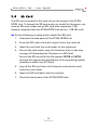
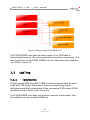
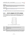
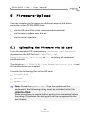
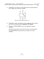
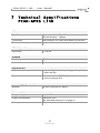
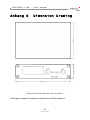
1
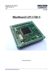
PCAN-GPRS Link
Platform for Telematic Applications
User Manual
V1.0.4
PCAN-GPRS Link – User Manual
Products taken into account
Product Name
Model
Item Number
evaluation version
IPEH-004000-EVAL
PCAN-GPRS Link
PCAN-GPRS Link Set
IPEH-004000
CANopen® and CiA® are registered community trade marks of CAN in Automation
e.V.
All other product names mentioned in this document may bet he trademarks or
registered trademarks of their respective companies. They are not explicitly marked
by „™“ and „®“.
© 2011 PEAK-System Technik GmbH
PEAK-System Technik GmbH
Otto-Röhm-Straße 69
64293 Darmstadt
Germany
Phone:
Fax:
+49 (0)6151 8173-20
+49 (0)6151 8173-29
www.peak-system.com
[email protected]
Document version 1.0.4 (2011-10-18)
2
PCAN-GPRS Link – User Manual
Contents
1
1.1
1.2
1.3
2
Introduction
5
Properties of a Glance
Prerequisites for Operation
Scope of Supply
Hardware
5
7
7
9
2.1 Pin Assignment Automotive Connector
2.2 Microcontroller LPC2368
2.3 GPS-Module u-blox LEA-5S
2.4 GPRS-Module Wavecom Wireless CPU WMP50
2.5 Extension
2.5.1 Pin Header 1 - J2
2.5.2 Pin Header 2 - J5
2.6 SD Card
10
10
11
11
12
13
13
14
3
15
Operation
3.1 Status LEDs
3.2 Wake-up
3.3 Cabling
3.3.1 Termination
3.3.2 Example of a Connection
3.3.3 Maximum Bus Length
15
16
17
17
18
18
4
Transfer CAN Data via TCP/IP
19
5
Firmware
20
5.1 Installing the WinARM Package
5.1.1 Decompressing the ZIP Archive
5.1.2 Setting up Additional Search Paths
5.2 Compiling Projects with gcc and µVision
3
20
21
21
23
PCAN-GPRS Link – User Manual
5.3 Microcontroller LPC2368
5.3.1 JTAG Pin Assignment ARM 20-Pin Connector
5.3.2 FMS Data
5.3.3 DTCO Data
5.3.4 GPS Data
5.3.5 OBD-2 via CAN
5.4 Wavecom Wireless CPU WMP50
25
26
27
28
28
29
32
6
34
6.1
6.2
6.3
7
Firmware-Upload
Uploading the Firmware via SD Card
34
Firmware Update over the Air
35
Uploading Firmware via the Serial Connections 35
Technical Specifications PCAN-GPRS Link
37
Anhang A
CE-Certificate
39
Anhang B
Dimension Drawing
40
Anhang C
Current Consumption PCAN-GPRS Link
41
4
PCAN-GPRS Link – User Manual
1
Introduction
PCAN-GPRS Link is a hardware and firmware platform for the
recording and forwarding of vehicle data. There are two freely
programmable microcontrollers within the unit which process
internal vehicle data.
The PCAN-GPRS Link is provided as a development platform for
telematic applications.
PCAN-GPRS Link supports the evaluation of FMS and Bus FMS data
(Fleet Management Standard). This produces consumption-related
vehicle data. The DTCO info interface also allows the connection
and processing of a digital tacho with access to information such as
driver identification and driver working time. The GPS module can
be used to determine location and output the direction of travel.
There is an optional expansion to allow any volume of additional
data to be processed, output and recorded. These include
temperature and movement sensors, barcode scanners, RFID
readers, displays and WIFI or Bluetooth connections.
1.1
Properties of a Glance
Dualcore ARM7 (core) and ARM9 (GPRS) system
U-blox 5 GPS module with 50 channels and over 1 Million
correlators. Position accuracy 2.5 m CEP at -130 dBm
Data transfer via GPRS or CSD
Wavecom GPRS class 10 quad-band modem
Handling of FMS data
Handling of DTCO data
5
PCAN-GPRS Link – User Manual
Handling of OBD-2 data via CAN (complete PID support not
ensured)
CiA® 447 protocol support on request
Support for the PCAN-Link software package by PEAK-System
Two High-speed CAN channels (ISO 11898-2) with bit rates of
40 kbit/s to 1 Mbit/s
Wake-up function
• via CAN
• via clamp 15 (ignition)
Two digital inputs
• Low- or High-active (depending on the circuit Pull-up/
-down)
One digital output
• Low-side driver (BSP75)
• Maximum inverse voltage 40 V
• Output current 500 mA
One UART V.24
DTCO (digital tacho) with input level 0 - 9 V DC
Internal flash memory (maximum 2 GB)
Firmware update over the air
5 individual extension pins (on the automotive connector)
6 dual LEDs free configurable, 1 LED fixed function (GPRS
modem)
Extended operating temperature range from -40 to 85 °C
(-40 to 185 °F)
6
PCAN-GPRS Link – User Manual
1.2
Prerequisites for Operation
Operating voltage: 6 - 32 V DC
FAKRA GSM/GPS combination antenna
For programming
• Windows 7/Vista/XP/2000
• SD card reader
• ARM Evaluation Software μVision from Keil
(www.keil.com/demo/eval/arm.htm)
For the demo server
• Linux server with root rights
• MySQL Server version 5 or higher
• MySQL connector C++ version 1.0.5 or higher
• Xerces XML Parser 2.8 or higher
1.3
Scope of Supply
PCAN-GPRS Link Set:
PCAN-GPRS Link in aluminum casing
Preconfigured cable set (CAN/Power/RS-232)
Installed 1 GB SD card
JTAG programming adapter
Additional set of crimp contacts
GPRS/GPS combination antenna
CD with library, software, programming example and manual in
PDF format
7
PCAN-GPRS Link – User Manual
PCAN-GPRS Link:
PCAN-GPRS Link in aluminum casing
Tyco mating connector including crimp contacts
CD with library, software, programming example and manual in
PDF format
8
PCAN-GPRS Link – User Manual
2
Hardware
Description of the hardware module.
Figure 1: Arrangement of the hardware on the board
9
PCAN-GPRS Link – User Manual
2.1
Pin Assignment Automotive Connector
Figure 2: Arrangement of the pins on the automotive connector
Pin Function
Pin
Function
1
14
Power supply (6 - 32 V)
Power supply (6 - 32 V)
2
GND
15
GND
3
For extension J2:10
16
For extension J2:7
4
For extension J2: 6
17
For extension J2:8
5
Clamp 15 (ignition)
18
For extension J2:4
6
Digital IN 1
19
UART CTS (Software)
7
Digital IN 0
20
UART RTS (Software)
8
Digital OUT
21
UART TxD
9
DTCO TxD
22
UART RxD
10
CAN 0 Low
23
CAN 0 Low
11
CAN 0 High
24
CAN 0 High
12
CAN 1 Low (FMS)
25
CAN 1 Low (FMS)
13
CAN 1 High (FMS)
26
CAN 1 High (FMS)
2.2
Microcontroller LPC2368
Basics
ARM 7
72 MHz
RTC
32,768 kHz
Flash
512 Kbyte
SRAM
32 Kbyte
10
PCAN-GPRS Link – User Manual
2.3
GPS-Module u-blox LEA-5S
Basics
Sensitivity
-160 dBm (SuperSense)
Receiver
50 channels with over 1 Million correlators
Accuracy
2,5 m CEP at -130 dBm
DGPS
SBAS (WAAS, EGNOS, MSAS, GAGAN)
2,0 m CEP at -130 dBm
Time To First Fix (TTFF)
Hot Start (Autonomous)
<1s
Warm Start
(Autonomous)
29 s
Cold Start
(Autonomous)
29 s
Antenna
Antenna feeder
3,3 V, maximum 50 mA
Minimum gain
15 - 20 dB
Maximum noise figure
1,5 dB
Maximum gain
50 dB
Impedance
50 Ω
Connector
FAKRA Code C
2.4
GPRS-Module Wavecom Wireless CPU WMP50
Basics
Data transfer
GPRS Class 10
Transmission power
1 W at 1800/1900 MHz
2 W at 900/800 MHz
Modem type
Quad band 800/900/1800/1900 MHz
ARM9
26 MHz (optional: WMP100 with 104 MHz)
11
PCAN-GPRS Link – User Manual
Antenna
VSWR max.
1,5:1
Impedance
50 Ω
Typical radiated gain
0 dBi
Connector
FAKRA Code D
2.5
Extension
It is possible to extend the hardware using two pin headers.
Following pins on these pin header are available:
Figure 3: Pin header 1 - J2, pin header 2 - J5
12
PCAN-GPRS Link – User Manual
2.5.1
Pin Header 1 - J2
Pin
Function
Pin
Function
1
Supply voltage, maximum
500 mA
6
Extension (Pin 4 automotive connector)
2
RESERVED
7
Extension (Pin 16
automotive connector)
3
3,3 V maximum 100 mA
8
Extension (Pin 17
automotive connector)
4
Extension (Pin 18
automotive connector)
9
GND
5
5 V, maximum 500 mA
10
Extension (Pin 3 automotive connector)
2.5.2
Pin Header 2 - J5
Pin
Function
Pin
Function
1
Global reset (Low-active)
8
Extension microcontroller: P0.15
(P0[15], TXD1, SCK0 (SSP0), SCK
(SPI))
2
Start microcontroller with
internal boot loader
9
3,3 V, maximum 100 mA
3
Extension microcontroller:
P0.26 (P0[26], AD0[3],
AOUT, RXD3)
10
GND
4
Extension microcontroller:
P0.18 (P0[18], DCD1,
MOSI0 (SSP0), MOSI
(SPI))
11
UART 3 microcontroller Software CTS
5
Module Identification micro- 12
controller: P0.23 (P0[23],
AD0[0], I2SRX_CLK,
CAP3[0])
UART 3 microcontroller Software RTS
6
Extension microcontroller:
P0.17 (P0[17], CTS1,
MISO0 (SSP0), MISO
(SPI))
13
UART 3 microcontroller TxD
7
Extension microcontroller:
P0.16 (P0[16], RXD1,
SSEL0 (SSP0), SSEL (SPI))
14
UART 3 microcontroller RxD
13
PCAN-GPRS Link – User Manual
2.6
SD Card
The SD card is located in the card slot on the board of the PCANGPRS Link. To format the SD card and/or to install the firmware, you
need an SD card reader and an SD card with maximum 2 GB
capacity (supplied with the PCAN-GPRS Link set is a 1 GB SD card)
Do the following to setup and/or install the SD card:
1.
Unscrew the back panel of the PCAN-GPRS Link.
2.
Press the SD card at its end to eject it from the card slot.
3.
Insert the card into the card reader on the computer.
4.
Format the card and/or copy the firmware onto it (see also
on page 34 Uploading the Firmware via SD Card).
Format the SD card with the file system FAT16 or FAT32
through the appropriate application of the operating system
(maximum sector size 512 byte).
5.
Log off the SD card from the Computer and take the card
from the card reader.
6.
Insert the SD card back into the card slot.
7.
Close the back panel of the PCAN-GPRS Link.
14
PCAN-GPRS Link – User Manual
3
Operation
The power supply of the PCAN-GPRS Link is switched on by applying the supply voltage. To save power it is possible to switch off the
internal power supply. Restart is only possible via CAN or clamp 15
(ignition). The RTC from the microcontroller and the GPS are still
supplied. This allows a fast GPS Fix.
Attention! The GSM antenna must always be connected! If this
is not the case, the transmitter can be damaged.
3.1
Status LEDs
Figure 4: Layout of the LEDs on the PCAN-GPRS Link
LED
Status
Meaning
Supply
Green blinking
Supply voltage available
GPRS
Green static
Modem ready
Green blinking
GPRS connection established
Red blinking
Waiting for valid NEMA data
(during GPS receiver initialization)
Green blinking
GPS receiver ready, forwarding valid
NEMA data without GPS position data.
Waiting for GPS fix
Green static
Valid GPS position found. GPS receiver
forwarding valid NEMA data with
GPS position data
Red blinking
FMS data not valid
Green blinking
FMS data valid
GPS
FMS
15
PCAN-GPRS Link – User Manual
LED
Status
OBD-2
Red blinking
No valid OBD-2 data received
Green blinking
Valid OBD-2 data received
Memory Off
DTCO
Meaning
No SD card found
Green blinking
SD card found, Log is running
Off
No DTCO found
Red blinking
No valid DTCO data found
Green blinking
DTCO data valid
Note: All LEDs, except for the GPRS LED, are freely
configurable. Blink patterns are fixed in the LIB.
3.2
Wake-up
If the PCAN-GPRS Link is in Sleep mode, the operation will be
resumed by a wake-up signal.
Following possibilities are available for activating the PCAN-GPRS
Link by a wake-up signal:
CAN: When a message is received via CAN 1 or CAN 2, the
PCAN-GPRS Link turns on. Within the wake-up time of 370 ms
further incoming CAN messages are not processed.
Clamp 15 (ignition): With a positive level on clamp 15 the PCANGPRS Link is set in operation. The wake-up time is also 370 ms.
16
PCAN-GPRS Link – User Manual
Figure 5: Power supply PCAN-GPRS Link
The PCAN-GPRS Link goes to sleep mode, if no CAN data is
transmitted/received, the microcontroller is inactive, and clamp 15 is
low. Activation of the PCAN-GPRS Link is in this case only possible
via CAN or clamp 15.
3.3
3.3.1
Cabling
Termination
A High-speed CAN bus (ISO 11898-2) must be terminated on both
ends with 120 Ohms. Otherwise, there are interfering signal
reflections and the transceivers of the connected CAN nodes (CAN
interface, control device) will not work.
The PCAN-GPRS Link does not have an internal termination. Use
the adapter on a terminated CAN bus.
17
PCAN-GPRS Link – User Manual
3.3.2
Example of a Connection
Figure 6: Simple CAN connection
In this example, the PCAN-GPRS Link is connected with a control
unit by a cable that is terminated at both ends.
3.3.3
Maximum Bus Length
CAN networks may have bit rates of up to 1 Mbit/s, where all CAN
nodes must be able to process messages simultaneously. The
maximum bus length depends on the bit rate.
The following table shows some examples with the bus length in
relation to the bit rate:
Bit rate
Max. bus length
125 kbit/s
530 m (580 yards)
250 kbit/s
270 m (300 yards)
500 kbit/s
130 m (140 yards)
1 Mbit/s
40 m (45 yards)
Note: The PCAN-GPRS Link is set by default to 500 kbit/s. Only
in the case of the use of FMS used standard is 250 kbit/s. All
other bit rates can be used freely.
18
PCAN-GPRS Link – User Manual
4
Transfer CAN Data via
TCP/IP
The PCAN-Link software package allows the transfer of CAN data
using TCP/IP. PCAN-Link is based on the CANAPI2 interface by
PEAK-System, thus supporting various communication scenarios
(PCAN-Link is not included in the scope of supply).
Several virtual or physical CAN networks can be connected via a
network medium.
A simple PCAN-Link client can be integrated in the PCAN-GPRS
Link. Note that the data rates of GPRS are 50 kbit/s in the best case.
For more information about PCAN-Link visit our website:
www.peak-system.com
19
PCAN-GPRS Link – User Manual
5
Firmware
The WinARM software provided can be used to produce your own
firmware. This chapter describes the installation of the package.
Furthermore, the properties for the programming of CPUs are
described.
Note: You need the WinARM package only if you don’t have the
full version of the μVision development environment!
The ARM Evaluation Software μVision from Keil to compile the
firmware can be found at:
https://www.keil.com/arm/demo/eval/arm.htm
Attention! From μVision version 4.20, there is currently no gcc
support. Use the version 4.13 or less.
5.1
Installing the WinARM Package
This chapter covers the installation of the program package
WinARM. Software, source code, and additional information is
included on the supplied CD in the following directory branch:
/tools
WinARM is collection of tools to develop applications for ARM
processors and microcontrollers on Windows platforms. The
package includes the GNU GCC Compiler for C and C++.
The installation of the WinARM package is done in two major steps,
the decompression of the ZIP archive and the setup of additional
search paths under Windows.
20
PCAN-GPRS Link – User Manual
5.1.1
Decompressing the ZIP Archive
From the supplied CD, subdirectory tools decompress the ZIP
archive winarm.zip to C:\ including all contained subdirectories.
During this action the directory C:\WinARM and subdirectories are
created.
You can get more information about the WinARM package by
starting the file readme.htm from the installation directory
C:\WinARM.
5.1.2
Setting up Additional Search Paths
In order to enable Windows to find the development tools on
calling, the according directories must be added to the search paths
(environment variable PATH):
C:\WinARM\bin;
Do the following to setup the additional search paths:
1.
Make sure that you are logged in as user with administrator
privileges.
2.
Press the key combination á + Pause.
Under Windows 2000 and XP the dialog box System
Properties is shown, under Windows Vista and 7 the
window System.
3.
Windows Vista and 7 only: Click on Advanced system
settings. If requested, enter an administrator password and
confirm that the procedure shall be continued.
The dialog box System Properties is shown.
4.
Open the tab Advanced and on this tab click on
Environment Variables.
The corresponding dialog box is shown.
21
PCAN-GPRS Link – User Manual
5.
In the System variables click on the item Path and then on
Edit.
The dialog box Edit System Variable is shown.
6.
Add the following character string to the allready existing
contents of the field Variable value:
C:\WinARM\bin;
Make sure that this character string is separated from the
previous contents by a semicolon (;) and without a space.
Close this and each preceding dialog box with OK.
Note: The new search paths are effective only for programs and
command prompts that are started afterwards.
22
PCAN-GPRS Link – User Manual
5.2
Compiling Projects with gcc and
µVision
1.
Copy and unzip from the CD from the subdirectory
Firmware the example project
(PCAN-GPRS_Link_ExampleProjekt_V1.6.0.zip) to your hard
disk.
2.
Open the PCAN-GPRS Link project
GPRS-Link_example.uvproj.
3.
Select GPRS-Link GCC o0 Bootloader.
4.
Open the file extensions, books, and environment and check
the followings points at the tab Folders/Extensions:
23
PCAN-GPRS Link – User Manual
Indication in the field GNU-Tool-Prefix: arm-glueIndication in the field GNU-Tool-Folder: the path of your
winarm installtion.
Finally confirm the settings with OK.
5.
To compile the firmware use the function key F7 or click to
the button Build.
Find more information about uploading the firmware in chapter 6
Firmware-Upload on page 34.
Note: The generated BIN file is about 60% larger than the
supplied file by PEAK-System. This is due to the unused
optimization in gcc. Don’t use this optimization, since this can
lead to malfunctions of the LIB.
24
PCAN-GPRS Link – User Manual
5.3
Microcontroller LPC2368
The microcontroller LPC2368 can be programmed freely. A demo
application representing a simple telematic system is included.
Debug / Programming
JTAG (J1)
SMD Connector 0.08 inch (2 mm)
UART (J6)
UART0, Connector 0.08 inch (2 mm)
Following libraries are available on the CD (for gcc and RealView
compilers). All low-level functions are integrated in one LIB. All
high-level functions are delivered in separate LIBs.
Low-level
CAN
Standard CAN API by PEAK-System
UART
UART control
EEPROM
I²C control at EEPROM
MCI
MMC/SD card control
LED
LED control
RTC
Real-time clock
DMA
Use of internal DMA controllers
High-level
1
FMS
Analysis of FMS data
DTCO
Analysis of DTCO data
GPS
Analysis of GPS data
OBD-2
Request and analysis of OBD-2 data
GPRS
Control of the modem and the connection to the internet
LOG
Save the data FMS, OBD-2 and GPS data in KML format (Google
Earth) 1
DEBUG
Debug output of GPRS-Link
To view the GPS data in KML format, you have to install Google Earth on your
computer. Make sure that you will use an appropriate license from Google for your
application.
25
PCAN-GPRS Link – User Manual
High-level
PCAN Link
Simple PCAN-Link Client
Socket
Functions to establish a socket connection
Source code
FAT
File system for MMC/SD card
http://elm-chan.org/fsw/ff/00index_e.html
Note: All listed data can be accessed internally by data arrays.
5.3.1
JTAG Pin Assignment ARM 20-Pin Connector
With the supplied JTAG adapter you can program and reset the
module (push button). Plug the supplied JTAG adapter on J1. The
0.1 inch (2,54mm) pin connector fits to all standard ARM JTAG
interfaces.
Figure 7: Pin Assignment ARM 20-Pin connector
Signal
Connects to…
TMS
Test Mode State pin - Use 100 kΩ pull-up resistor to VCC
TDO
Test Data Out pin
RTCK
JTAG Return Test Clock
TDI
Test Data In pin - Use 100 kΩ pull-up resistor to VCC
TRST
Test ReSet pin - Use 100 kΩ pull-up resistor to VCC. TRST is optional
and not available on some devices. You may leave it unconnected
26
PCAN-GPRS Link – User Manual
Signal
Connects to…
TCLK
Test Clock pin - Use 100 kΩ pull-up resistor to VCC
VCC
Positive Supply Voltage - Power supply for JTAG interface drivers
GND
Digital ground
RESET
RSTIN/ pin — Connect this pin to the (low-active) reset input of the
target CPU
5.3.2
FMS Data
Following data is provided through the FMS library:
PGN (hex)
Description
00FEF1
Wheel speed
00FEF1
Current status of clutch / brake / cruise control
00FEF1
Auxiliary drive (PTO)
00FEF1
Parking brake (only Bus FMS)
00F004
Engine speed
00FEE5
Engine total hours of operation
00FEE9
Fuel consumption
00F003
Accelerator pedal position 1
00FEFC
Fuel level
00FEEC
Vehicle identification number
00FDD1
FMS-standard interface
00FDD1
Diagnostic support
00FEC0
Service distance
00FEC1
High resolution total vehicle distance
00FE6C
Driver working state
00FE6C
Tachograph vehicle speed
00FEEA
Axle weight
00FEEE
Engine coolant temperature
00FE4E
Door control 1 (only Bus FMS)
00FDA5
Door control 2 (only Bus FMS)
00FEF5
Ambient Air Temperature (only Bus FMS)
00F005
Electronic transmission controller (only Bus FMS)
00FE58
Air suspension control (only Bus FMS)
27
PCAN-GPRS Link – User Manual
PGN (hex)
Description
00FEAE
Air supply pressure (only Bus FMS)
00FEE6
Time/Date (only Bus FMS)
00FED5
Alternator status (only Bus FMS)
5.3.3
DTCO Data
The DTCO info interface allows the connection and processing of a
digital tachometer with access to information about vehicle, driver
identification and driver working time.
Following data is provided through the DTCO library:
No.
Description
1
Driver data
2
Driver ID
3
Speed
4
K factor (technical constant of the tachometer, specifies the input
revolutions per kilometer)
5
Total kilometers
6
Trip kilometers
7
Vehicle ID
8
Ignition on/off
5.3.4
GPS Data
Following data is provided through the GPS library:
Param.
Description
latDeg
Latitude (WGS84-Koordinate)
latMin
Latitude minutes (WSG84-Koordinate)
lonDeg
Longitude (WGS84-Koordinate)
lonMin
Longitude minutes (WSG84-Koordinate)
Alti
Altitude
course
Course
speedK
Speed in km/h
28
PCAN-GPRS Link – User Manual
Param.
Description
speedN
Speed in kn/h
satsUsed
Number of satellites used in navigation solution, 00 - 12
satsInView
Number of GPS satellites in view
Hacc
Horizontal accuracy estimate
Vacc
Vertical accuracy estimate
HDOP
Horizontal Dilution of Precision
VDOP
Vertical Dilution of Precision
TDOP
Time Dilution of Precision
5.3.5
OBD-2 via CAN
Read and reset the error codes and the Malfunction Indicator Light
(MIL). The PIDs to be queried must be defined in the firmware.
Note: The complete support of all the PIDs of all vehicles can
not be guaranteed.
PID (hex)
Description
0x01
System Status
0x02
DTC that caused required freeze frame data storage
0x03
Fuel system status
0x04
Calculated LOAD value
0x05
Engine Coolant Temperature
0x06, 0x08
Short Term Fuel Trim
0x07, 0x09
Long Term Fuel Trim
0x0A
Fuel Rail Pressure (gauge)
0x0B
Intake Manifold Absolute Pressure
0x0C
Engine RPM
0x0D
Vehicle Speed Sensor
0x0E
Ignition Timing Advance
0x0F
Intake Air Temperature
0x10
Air Flow Rate form Mass Air Flow Sensor
0x11
Absolute Throttle Position
29
PCAN-GPRS Link – User Manual
PID (hex)
Description
0x12
Command Secondary Air Status
0x13, 0x1D
Location of oxygen sensors
0x14 - 0x1B
Oxygen sensor value
0x1C
OBD requirements to which vehicle or engine is certified.
0x1E
Auxiliary input status, Power take off (PTO) status
0x1F
Time since engine start
0x21
Distance traveled while MIL is activated
0x22
Fuel rail pressure relative to manifold vacuum
0x23 - 0x2B
Fuel rail pressure
0x2C
Commanded EGR
0x2D
EGR Error
0x2E
Commanded Evaporative purge
0x2F
Fuel level input
0x30
Number of warm-ups since DTCs cleared
0x31
Distance traveled since DTC cleared
0x32
Evap system vapor pressure
0x33-0x3B
Barometric pressure
0x3C - 0x3F
Catalyst Temperature Sensor
0x41
Monitor status this driving cycle
0x42
Control module voltage
0x43
Absolute load value
0x44
Fuel / Air commanded equivalence ratio
0x45
Relative throttle position
0x46
Ambient air temperature
0x47 - 0x48
Absolute throttle position
0x49 - 0x4B
Accelerator pedal position
0x4C
Commanded throttle actuator control
0x4D
Engine run time while MIL is activated
0x4E
Engine run time since DTCs cleared
0x4F - 0x50
External test equipment configuration information
0x51
Type of fuel currently being utilized by the vehicle
0x52
Alcohol fuel percentage
0x53
Absolute evap system vapor pressure
30
PCAN-GPRS Link – User Manual
PID (hex)
Description
0x54
Evap system vapor pressure
0x55, 0x57
Short term secondary O2 sensor fuel trim
0x56, 0x58
Long term secondary O2 sensor fuel trim
0x59
Fuel rail pressure
0x5A
Relative accelerator pedal position
0x5B
Hybrid battery pack remaining life
0x5C
Engine oil temperature
0x5D
Fuel injection timing
0x5E
Engine fuel rate
0x5F
Emission requirements to which vehicle is designed
0x61
Driver's demand engine - percent torque
0x62
Actual engine - percent torque
0x63
Engine reference torque
0x64
Engine percent torque data
0x65
Auxiliary input / output supported
0x66
Mass air flow sensor
0x67
Engine coolant temperature
0x68
Intake air temperature sensor
0x69
Commanded EGR and EGR Error
0x6A
Commanded Diesel intake air flow control and relative intake air
flow position
0x6B
Exhaust gas recirculation temperature
0x6C
Commanded throttle actuator control and relative throttle
position
0x6D
Fuel pressure control system
0x6E
Injection pressure control system
0x6F
Turbocharger compressor inlet pressure
0x70
Boost pressure control
0x71
Variable Geometry turbo (VGT) control
0x72
Wastegate control
0x73
Exhaust pressure
0x74
Turbocharger RPM
0x75 - 0x76
Turbocharger temperature
0x77
Charge air cooler temperature (CACT)
31
PCAN-GPRS Link – User Manual
PID (hex)
Description
0x78 - 0x79
Exhaust Gas temperature (EGT)
0x7A - 0x7B
Diesel particulate filter (DPF)
0x7C
Diesel Particulate filter (DPF) temperature
0x7D
NOx NTE control area status
0x7E
PM NTE control area status
0x7F
Engine run time
0x81 - 0x82
Engine run time for AECD
0x83
NOx sensor
0x84
Manifold surface temperature
0x85
NOx reagent system
0x86
Particulate matter (PM) sensor
0x87
Intake manifold absolute pressure
0x88 - 0xFF
ISO / SAE reserved
5.4
Wavecom Wireless CPU WMP50
The wireless CPU can be delivered fully programmed. These
options are available:
Encrypted communication over SSL only possible with
WMP100. For larger values, the WMP100 can be ordered instead
of the WMP50
Unsecured communication
The wireless CPU can be reprogrammed according to your
requirements. Examples are supplied.
For more information visit the Wavecom website:
www.wavecom.com.
Basics
Encoding
(only
WMP100)
Authentication: RSA
Encoding: 3DES
32
PCAN-GPRS Link – User Manual
Debug / Programming
UART
UART 2-mm pin header, maximum level 3,3V
Activated Open AT Plugins
Security
Secured Sockets Layer SSL 3.0 / SSL 2.0
(only WMP100) Jamming Detection
HTTPS
Crypto Library
Open SIM Access
Internet
TCP/IP Stack Sockets: 8 UDP Client, 8 TCP Client, 4 TCP Server
Protocols: UDP, TCP Client, TCP Server, FTP, HTTP, SMTP, POP3
33
PCAN-GPRS Link – User Manual
6
Firmware-Upload
You can transfer the firmware on different ways to the microcontroller of the PCAN-GPRS Link.
via the SD card (this is the recommended method)
via firmware update over the air
via the serial interface
6.1
Uploading the Firmware via SD Card
From the supplied CD, subdirectory \Software and Firmware\
decompress the ZIP-Archive PCAN-GPRS_Link_
ExampleProject_Vx.x.x.zip to C:\ including all contained
subdirectories.
The directory C:\ PCAN-GPRS_Link_ExampleProject_Vx.x.x and
all subdirectories are created.
Transfer the following files to the SD card:
FirmCRC.BIN
crc.txt
update.ini
Note: Check the update.ini. Thus the update will be
performed, the following string must be included in the file:
UPDATE=TRUE.
Write everything in capital letters and put no characters before
the string. Otherwise, the string will not be recognized by the
boot loader.
34
PCAN-GPRS Link – User Manual
After inserting the SD card into the PCAN-GPRS Link the module
starts programming itself. Switch the module off and on again.
6.2
Firmware Update over the Air
Using the internal boot loader, a firmware update over the air can
be done. To keep all update options open the GPRS interface is not
predefined by Peak-System. Transfer the files FirmCRC.bin,
crc.txt and update.ini on any path onto the module so that
you can use the update.
After the data is transmitted, the microcontroller writes the data to
the SD card. After a reset the module will start by itself.
6.3
Uploading Firmware via the Serial
Connections
This section shows how to initiate the microcontroller’s boot loader.
The actual upload process is done with the tool Flash Magic (on the
CD in the directory tools), which is supplied by a third party and is
not described here. You can get more details from our customer
support (see address on page 2).
Attention! If you transmit the firmware with this procedure, the
boot loader for the update via SD card will be overwritten
Do the following to initiate the microcontroller’s boot loader:
1.
Switch the PCAN-GPRS Link off by disconnecting it from the
power supply.
2.
Open the casing of the PCAN-GPRS Link by removing the
screws in order to gain access to the board.
35
PCAN-GPRS Link – User Manual
3.
Establish a connection on the J6 connector panel between
pin 4 (/Boot_ser) and pin 5 (GND).
Figure 8: Connection at connector J6
4.
Establish a serial connection to the computer via the serial
port of the microcontroller (attention: TTL levels).
5.
Switch the PCAN-GPRS Link on by applying a supply
voltage.
Due to the Low level on port P0.14 of the microcontroller,
the PCAN-GPRS Link starts the boot loader for serial
transfer.
36
PCAN-GPRS Link – User Manual
7
Technical Specifications
PCAN-GPRS Link
CAN
Specification
High-speed CAN ISO 11898-2
Bit rate 40 kbit/s - 1 Mbit/s
Transceiver
NXP (Philips) TJA 1041 (with wake-up function)
Termination
optional
DTCO (Digital Tacho)
Input level
0 - 9 V DC
EEPROM
Memory space
256 kbit
Control
I²C
Digital IN/OUT
Inputs
2 Low- or High-active (depending on the pull-up/down wiring)
Output
1 Low-side driver (BSP75), 500 mA, maximum
reverse voltage 40 V
Internal logging memory
Medium
SD card, maximum 2 GByte
Power supply
Supply voltage
6 - 32 V DC
Power consumption
150 mA at 12 V
See also table Anhang C on page 41
Startup time
370 ms
37
PCAN-GPRS Link – User Manual
Measure
Board size
Casing size
100 x 24 x 80 mm (W x H x D)
105 x 30 x 85 mm (W x H x D)
See also dimension drawing
Anhang B on page 40
Weight
70 g (only board)
270 g (with casing)
Environment
Operating temperature
-40 - +85 °C (-40 - +185 °F)
Temperature for storage and
transport
-40 - +100 °C (-40 - +212°F)
Relative humidity
15% - 90%, not condensing
Tests / approvals
EMV
ETSI EN 301 489-1 /-3 /-7
ETSI EN 300 440
ETSI EN 301 511
DIN EN 61326-1:2006 + Corrigenda:2008-06
DIN EN 55011:2009
EC directive 2004/108/EG
Car directive 2009/19/EG
Safety requirements
DIN EN 61010-1:2002 + Corrigenda1:2002-11 +
Corrigenda2:2004-01
Protection class (DIN EN 60529)
IP20
Type approval
38
PCAN-GPRS Link – User Manual
Anhang A
CE-Certificate
39
PCAN-GPRS Link – User Manual
Anhang B
Dimension Drawing
Figure 9: Top view and view of the front side.
The figure doesn’t show the actual size of the product.
40
PCAN-GPRS Link – User Manual
Anhang C
Current Consumption PCAN-GPRS Link
The tables list the current consumption of the PCAN-GPRS Link. It has been rounded to whole mA.
Voltage
12 V
Power CAN1
[mA]
/CAN2
61
Active 0% No card
No traffic
63
116
LEDs
All OFF
GPS
LPC
OFF
while(1)
Comments
OFF
OFF
TRACKING
SLEEP
Averaged over 60 s
OFF
14
SLEEP
20
Active 0%
13
SLEEP
μC Sleep Mode, wake-up over
RTC is possible
μC Sleep Mode, wake-up over
RTC is possible
1
80
GPRS
SEARCHING
96
56
SD card
Active
99%
Power
down
μC power down mode,
wake-up over RTC is
possible
OFF
Power supply OFF,
wake-up over CAN
transmit
CAN
41
PCAN-GPRS Link – User Manual
Voltage
Power CAN1
[mA]
/CAN2
78
SD card
LEDs
SLEEP
GPS
LPC
All on
while(1)
Summary of current consumption:
Current at 12 V
mA
GPS, searching
53
GPS, tracking
33
Per LED
1,8
Per CAN bus, 99% busload
8,5
Per CAN bus, 0% busload
3,5
SD card standby
2
Wireless CPU(GPRS) active standby
18
Module standby
1
42
GPRS
Comments