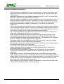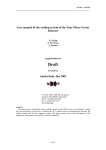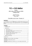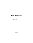
1
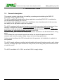
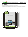
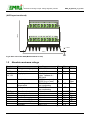
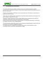
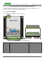
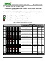
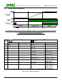
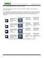
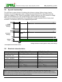
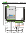
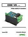
EME VD
V1.02
Voltage regulator for generators
January 2006
Instruction Manual
Generator rewinding & repair. Voltage regulator products
EME_VD_Manual_V1_31.doc
WARNINGS
WARNING
The system should not be installed, operated, serviced or
modified except by qualified personnel who understand
the danger of electric shock hazards and have read and
understood the user instructions
.
WARNING
Never work on a LIVE generator. Unless there is another
person present who can switch of the power supply or
stop the engine
WARNING
Dangerous voltages are present at the voltage regulator
board. Accidental contact with live conductors could result
in serious electrical shock or electrocution.
Disconnect the power source before making repairs,
connecting test instruments, or removing or making
connections to the voltage regulator or generator.
ELECTRICAL HAZARDOUS VOLTAGES
DANGEROUS DO NOT OPERATE WHEN
NOT FAMILIAR WITH GENERATORS
The manual does not cover all technical details of the product. Specifications may be modified
by the manufacturer without notice. For further information, the manufacturer should be
contacted.
Version : 1/25/2006 9:25:00
Page 2 of 19
Generator rewinding & repair. Voltage regulator products
EME_VD_Manual_V1_31.doc
Table of contents
WARNINGS
2
Chapter 1
1.0
1.1
1.2
1.3
Introduction
General description
AVR Layout
Absolute maximum ratings
Commissioning information
4
5
6
7
Chapter 2
2.0
2.1
2.2
2.3
2.4
2.5
2.6
2.7
2.8
2.9
Installation and maintenance
Connection diagram
Running state and LED error codes
Power-up routine and diagnose
Adjusting and factory settings
Special functionality
Electrical characteristics
Wiring diagram
Fault diagnostics (diagrams)
Factory settings
General installation information
8
9
10
11
12
12
13
14
17
18
Version : 1/25/2006 9:25:00
Page 3 of 19
Generator rewinding & repair. Voltage regulator products
EME_VD_Manual_V1_31.doc
1. INTRODUCTION
1.0
General description
This manual contains instructions for installing, operating and maintaining the EME VD
automatic voltage regulator (AVR).
The AVR is specifically designed for railway application according EN 50155 in combination
with brushless generators 400 V/50 Hz.
It is however very applicable for generator installations where high demands for the accuracy
and safety for the generator output are requested.
The AVR is equipped with security functions to protect the generator load and equipment from
damage or dangerous situations. Critical protections are implemented redundant. The
protection circuits as well as the operational status feedback interface contact are tested upon
every power up, before the generator is excited by the AVR.
The AVR is designed to meet the railway requirements described in the EN 50155:2004, rolling
stock.
This contains the environmental aspects as well as the electrical aspects such as EMC
emission and immunity, supply voltage range, and overvoltage protections.
Under normal conditions the AVR is placed inside the generator but installation in cabinets is
also possible.
The AVR is partly software controlled and deliverable with special functions such as soft voltage
recovery at voltage dips upon switched on heavy loads, when using soft prime movers such as
a hydraulic motor.
The AVR is available for 0-110Vdc as well as 0-24Vdc supply voltage.
Version : 1/25/2006 9:25:00
Page 4 of 19
Generator rewinding & repair. Voltage regulator products
1.1
EME_VD_Manual_V1_31.doc
AVR Layout
The AVR is protected from the environment by an epoxy coating.
The bottom of the AVR has a special Protective Earth (PE) connection surface shown as PE in
figure 2.
Connection terminals are locked by screws and are not exchangeable as a consequence of a
coding system.
C1 C2
T36 T37
Remove
bridge when
using external
pot. Meter
D I PV
I
t
s
2
1
W
Ready
V
Error
U
Fig 1. Top view AVR (Measurements in mm)
Version : 1/25/2006 9:25:00
Page 5 of 19
160mm
140mm
180mm
EME VD REG
Generator rewinding & repair. Voltage regulator products
EME_VD_Manual_V1_31.doc
(AVR layout continued)
105m m
t
s
2
1
W
V
U
110V 0V K1 J1 UH VH UH’ VH’ C NO
5.5mm
130mm
PE
Fig 2. Rear view of the AVR (Measurements in mm)
1.2
Absolute maximum ratings
Symbol
U,V,W
Parameter
Voltage sensing input
Condition
< 30 s. 50 Hz.
J1, K1
UH, VH
UH’, VH’
Field excitation current
Supply input
Rfield
Field resistance
Tamb
Operating ambient
temperature
Storage temperature
Typical 4 Adc
1- or 3-phase.
or two 1-phase dc 400 Hertz
@ 100 VUH-VH (rms)
@ 230 VUH-VH (rms)
100 % RHD
non condensing
95 % RHD
non condensing
Isolated
Isolated
Isolated
Isolated
Isolated
- 5%
THD < 5 %
Tstg
NO, C
T36, T37
1, 2
0-24 V
0-110V
s, t
Operational output
Clixon input
Droop input
Electronics supply
Electronics supply
External Volt adjust
Accuracy
Min.
-
Max.
500
Unit
Vac
20
5
240
Adc
V
4
10
-20
+85
Ohm
Ohm
ºC
-45
+85
ºC
0
18
77
0
Table 1. Absolute maximum ratings
Version : 1/25/2006 9:25:00
Page 6 of 19
5A/30V DC
Ohm
0.5
Aac
39
Vdc
138
Vdc
5K
Ohm
1%
Generator rewinding & repair. Voltage regulator products
1.3
EME_VD_Manual_V1_31.doc
Commissioning information
The system should not be installed, operated, serviced or modified except by qualified
personnel who understand the danger of electric shock hazards and have read and understood
the user instructions.
Defects in the generator or AVR may cause consequential loss. Precautions must be taken to
prevent this from occurring.
Never work on a LIVE generator. Unless there is another person present who can switch of the
power supply or stop the prime mover.
Dangerous voltages are present at the voltage regulator board. Accidental contact with live
conductors could result in serious electrical shock or electrocution.
Disconnect the power source before making repairs, connecting test instruments, or removing
or making connections to the voltage regulator.
The unit should be installed with respect to the environmental specifications as well as the rules
mentioned in the General installation information.
For safety reasons the voltage LEVEL potentiometer is best turned completely counter
clockwise in order to start at the lowest possible voltage.
Version : 1/25/2006 9:25:00
Page 7 of 19
Generator rewinding & repair. Voltage regulator products
EME_VD_Manual_V1_31.doc
2. INSTALLATION AND MAINTENANCE
For safety reasons the voltage LEVEL potentiometers are best turned completely counter
clockwise in order to start at the lowest possible voltage
2.0
Connection diagram
For a complete wiring diagram see figure 4 on page 12.
T36
T37
EME VD REG
T
Remove
bridge whe n
usin g externa l
Voltage t rim
D I PV
S
2
1
W
V
Rea dy Erro r
110V 0V K1 J1 UH VH UH’ VH’ C
T
S
2
1
W
U
V
NO
U
Fig 3. Connectors (top and rear view)
Symbol
U, V, W
1&2
S&T
0 – 110 V
K1 & J1
UH & VH
UH’ & VH’
C & NO
T36 & T37
Description
Voltage sensing input
Droop input
External connector for remote voltage control
External electronic supply
AVR field excitation
Supply input
Supply input
Status contact
Clixon input
Table 2. Connecting diagram
Version : 1/25/2006 9:25:00
Page 8 of 19
Notes
0,5 Aac max (Vphase)
When used, remove bridge
24 Vdc also available
Closed when AVR operational
Overtemperature when open
Generator rewinding & repair. Voltage regulator products
2.1
EME_VD_Manual_V1_31.doc
Running state and LED error codes
Important: By removing the 110Vdc (or 24Vdc) power supply, error codes
will be lost!
To read out the error code, the 110Vdc (or 24Vdc) power supply must remain connected after an
error occurred. In order to reset the AVR, remove the 110Vdc (or 24Vdc) power supply for at least
5 seconds.
Green LED off:
Diagnose fault AVR, AVR not running
Green LED on:
No diagnose fault, AVR running
Red LED on:
Fault and error, AVR not running
Table 2. LED status and corresponding error codes
No. of Blinks Red LED
Error Description
Green LED off
Green LED On
Value
Time
1
Operational contact selftest
failure
Undervoltage
380V
>5s
2
Supply relais selftest failure
Undervoltage 340V
>1s
3
Overvoltage selftest failure
Overvoltage
420V
>5s
4
Error reset selftest failure
Overvoltage
440V
>1s
5
Overtemperature selftest failure
Overvoltage
500V
>0,1s
6
Measurement selftest failure
Underspeed
45Hz
>5s
7
Phase loss selftest failure
Overspeed
55Hz
> 5s
8
Overtemperature
T36/T37 > 5 s
9
Phase loss
>0,1 s
T36-T37 > 5s
Critical Error
10
500V
Note: Critical error is either Overvoltage or Overtemperature (hardwired circuits)
Version : 1/25/2006 9:25:00
Page 9 of 19
>0,1s
Generator rewinding & repair. Voltage regulator products
2.2
EME_VD_Manual_V1_31.doc
Power-up and diagnose
For a successful self test, a remanent voltage of at least 11 Vac phase-phase and a frequency
between 45 and 55Hz have to be present.
Power-up self test takes approximately 15 seconds
Error
blink
code
Green LED off
Ready
Solution
Replace AVR.
2
Reason
Operational contact
failure
Supply relay failure
3
Over voltage failure
Replace AVR.
1
Replace AVR.
Green LED on
Reason
Voltage drop because of too
high load
Voltage drop because of too
high load
RPM of prime mover unstable
AVR defect
RPM of prime mover unstable
AVR defect
RPM of prime mover unstable
AVR defect
RPM of prime mover too low
Coupling defect
RPM of prime mover too high
Coupling defect
Over temperature
Solution
Reduce load
Check for short circuit
Reduce load
Reduce RPM
Replace AVR
Error
reset
failure
Replace
AVR.
Reduce RPM
4
Replace AVR
Temperature
failure
Replace
AVR.
Reduce RPM
5
Replace AVR
1
Check
sensing
wiring
.
Increase
RPM
Measurement
failure
6
Replace AVR.
Replace coupling
Phase loss failure
Replace AVR.
Reduce RPM
7
Replace coupling
Check ventilation
8
Clean housing
Phase loss
Check wiring
9
Short circuit
Check short circuit
Critical error
Reduce RPM
10
Check ventilation
Clean housing
Replace AVR
Note 1: For a successful selftest a minimum remanent voltage of 11V phase-phase has to be present.
Table 3. Error codes and solutions
Version : 1/25/2006 9:25:00
Page 10 of 19
Generator rewinding & repair. Voltage regulator products
2.3
EME_VD_Manual_V1_31.doc
ADJUSTING AND FACTORY SETTINGS
When delivered the AVR is ready to use with pre set factory settings. These settings are
explained in table 4.
It is not advisable to change these settings because changing the factory settings can damage
the generator and cause high voltage. Adjusting may only be done by qualified personnel who
understand the danger of electric shock hazards and have read and understood the user
instructions
100
100
100
100
0
0
0
0
Factory default
Turning CW
Increase the
output voltage
Turning CCW
Decrease the
output voltage
Factory default
Turning CW
Increase the
Proportional gain
action
Turning CCW
Decrease the
Proportional gain
action
Factory default
Turning CW
Increase the
Integral action
Turning CCW
Decrease the
Integral action
Factory default
Turning CW
Increase the
amount of voltage
droop
Turning CCW
Decrease the
amount of voltage
droop
Voltage setpoint:
Adjust the
generator output
voltage
P action setpoint:
Adjust the P-action
control
characteristic
I action setpoint:
Adjust the I-action
control
characteristic
Droop setpoint:
Adjust the voltage
droop for parallel
operation
Table 4. Adjusting AVR setting (note CW=Clock wise CCW=Counter Clock wise)
Version : 1/25/2006 9:25:00
Page 11 of 19
Generator rewinding & repair. Voltage regulator products
2.4
EME_VD_Manual_V1_31.doc
Special functionality*
The AVR has a unique feature of reducing the reference voltage. When a heavy load is
switched on and the generator output voltage decreases below 370V, the AVR lowers the
reference voltage to 370V. When the generator voltage is equal to the AVR reference voltage
again, the AVR builds up to the normal voltage output threshold level again.
This feature prevents the generator from producing a voltage overshoot due to heavy load
switches in combination with an over-magnetized generator.
Voltage reference lowering due to heavy load change
* Not implemented on 24V version
2.5
Electrical characteristics
Parameter
Sensing voltage input
Supply input
UH, VH, UH’, VH’
Electronics supply
0-110Vdc / 0-24Vdc
Field excitation current
Field resistance
Voltage setpoint range
Operational contact
Ambient temperature
Storage temperature
EME VD 110Vdc AVR
3 x 400 V – 50 Hz
85V – 100Vac, 100 – 400 Hz
EME VD 24Vdc AVR
3 x 400 V – 50 Hz
85V – 100Vac, 100 – 400 Hz
77 – 138 Vdc
18 – 39 Vdc
3,7 A
6 – 10 L
± 5%
30V / 5Adc
-20ºC to +70ºC, non condensing
-30ºC to +55ºC, non condensing
3,7 A
6 – 10 L
± 5%
30V / 5Adc
-20ºC to +70ºC, non condensing
-30ºC to +55ºC, non condensing
Stresses above those listed under “Absolute Maximum Ratings” may cause permanent damage to the
device. This is a stress rating only and functional operation of the device at those or any other conditions above
those indicated in the operation listings of this specification is not implied. Exposure to maximum rating conditions
for extended periods may affect device reliability and lifetime.
Version : 1/25/2006 9:25:00
Page 12 of 19
Generator rewinding & repair. Voltage regulator products
2.6
EME_VD_Manual_V1_31.doc
Wiring diagram
T36
T3 7
V
P
I
D
volta ge
p-action stability
EME VD REG
i-action s tabilty
droop
R emove
b rid ge when
u sin g external
Voltage trim
D I PV
Ready
Error
Operat io nal
T
S
2
W
1
V
U
110V 0V K1 J1 UH VH UH’ VH’ C NO
Volt trim
10 kOhm
Operat io nal
N
P1
V
U
T
S1
OPTIONAL
DROOPKIT
W
GENERATOR OUTPUT, ROTATION
CLOCKWISE
Enabl e
STATOR
ROTOR
Fig 4. Wiring
Version : 1/25/2006 9:25:00
Page 13 of 19
EXCITER FI ELD
Generator rewinding & repair. Voltage regulator products
2.7
Fault diagnoses
420V Overvoltage
380V Undervoltage
Version : 1/25/2006 9:25:00
Page 14 of 19
EME_VD_Manual_V1_31.doc
Generator rewinding & repair. Voltage regulator products
440V Overvoltage
340V Undervoltage:
500V overvoltage:
Version : 1/25/2006 9:25:00
Page 15 of 19
EME_VD_Manual_V1_31.doc
Generator rewinding & repair. Voltage regulator products
Overspeed
Underspeed
Overtemperature
Version : 1/25/2006 9:25:00
Page 16 of 19
EME_VD_Manual_V1_31.doc
Generator rewinding & repair. Voltage regulator products
EME_VD_Manual_V1_31.doc
Phase loss
2.8
Factory settings
After service or repair the AVR is re-adjusted to factory settings which are:
Parameter
Value
Unit
Output Voltage
400
V
Under speed frequency
45
Hz
Over speed frequency
55
Hz
Droop
0
V
Version : 1/25/2006 9:25:00
Page 17 of 19
Generator rewinding & repair. Voltage regulator products
2.9
EME_VD_Manual_V1_31.doc
General installation information
Absolute Maximum Ratings
-
The Absolute Maximum Ratings are those limits for the device that, if exceeded, will
likely damage the device. Exceeding the absolute maximum ratings voids any
warranty and/or guarantee.
Mounting
Mounting of the product should be done in such a way that the absolute maximum
ambient temperature rating of the product will never be exceeded.
Mounting of the product should be done in such a way that maximum cooling
(direction of cooling ribs and direction of airflow) is achieved.
Mounting of the product should be done in such a way that no humid air can flow
through the product or condensation occurs.
Mounting of the product should be done in such a way that dust or other materials or
residue will not remain in or on the product.
Mounting of the product should be done in such a way that the maximum vibration is
not exceeded.
Mounting of the product should be done in such a way that personal contact with
persons is impossible.
Wiring
-
Diameter size of the wiring should be enough to carry the expected current. Wire
insulation should be enough to withstand the expected operating voltages and
temperatures.
To improve EMC emission and immunity, care should be taken for the lay out of the
wiring. This in respect to all wiring in the installation.
Keep current carrying wires as short as possible.
Keep wires carrying a total sum of zero Ampere close to each other, or in one single
cable. E.g. U, V, W or F+ and F-, or Phase and neutral, X1 and X2.
Avoid current carrying conductors next to sensing or control wiring. Especially current
controlled by SCR’s or PWM controlled transistors.
If sensitive sensing signal cables need to be laid across distance along other cabling,
shielded cable is preferred.
Keep the shield as long as possible and the wiring outside the shield as short as
possible. Do not solder or shrink the shield to a regular wire. Connect the original
shield to ground at one side with an as large as possible contact surface.
Version : 1/25/2006 9:25:00
Page 18 of 19
Generator rewinding & repair. Voltage regulator products
EME_VD_Manual_V1_31.doc
Additional installation information
-
-
-
-
When the product is supplied by means of a transformer, it should never be an autotransformer. Auto-transformers react as voltage sweep up coil and may cause high
voltage peaks.
Standard fit capacitors or over-voltage suppressers across F+ and F- or exciter field
terminals inside the generator should be removed.
When the product is supplied by means of a transformer, it should be able to carry at
least the maximum expected current. Advisable is, to have a transformer which can
carry twice the maximum expected current. Inductive loads make voltage sacks and
peeks into the secondary voltage of a transformer, from which the device may
malfunction.
It is not recommended to apply switches in dc outputs. It is preferred to use switches
in the ac supply inputs of devices. In case it is unavoidable to have switches in the dc
output of a device, action must be taken to avoid over voltage damage to the device
due to contact arcing. Use a voltage suppressor across the output.
It is not recommended to apply switches or fuses in the sensing lines. Defects can
cause high voltage situations due to over-excitation.
When using a step down transformer in medium or high voltage generators, the
transformer should be three phase (if three phase sensing), and the transformer
should be suitable for acting as a sensing transformer. If the transformer is unloaded,
connect a resistor to avoid voltage waveform distortion.
The phase relation from the generator to the AVR is important. Also when voltage
transformers and/ or current transformers are installed.
When using a step down or insulation transformer in the droop circuit, phase relation
from the generator to the AVR is important.
CT’s wiring, connected to the AVR should never be grounded.
Always disconnect electronic products, circuits and people before checking the
insulation resistance (Megger check).
Due to differences in generators impedance’s, EMC behavior is not predictable.
Therefore the commissioner / installer should be aware of proper and correct
installation.
Large, highly inductive, exciter stator windings can cause destructive high voltage
peaks. Adding a resistor from 10 to 20 times the exciter stator field resistance reduces
voltage spikes. If necessary filter can be fitted additionally. (e.g. snubber, RC-network)
Upon problems during commissioning, faulty behavior or defects in the generator,
consult the fault finding manual at our web site
Some advises may be overdone or seem extraordinary, but since the electrical rules
are the same everywhere, these advises are given.
Version : 1/25/2006 9:25:00
Page 19 of 19