1
ZEUS MVD PLC-CAN interface
v1.4 19-Feb-2001
PLC↔CAN interface
for the
ZEUS MicroVertex Detector (MVD)
Cooling System
Henk Boterenbrood
NIKHEF, Amsterdam
February 2000
USER DOCUMENTATION Version 1.4
ABSTRACT:
This document describes the CANopen interface to the CAN-module that provides an interface to the PLC that controls the ZEUS Microvertex Detector (MVD) cooling system. The
SPICAN CAN-module equipped with this application firmware is referred to as PLC-CAN in
this note.
Contents
1
INTRODUCTION .............................................................................................................. 2
2
OPERATION...................................................................................................................... 3
2.1
2.2
2.3
2.4
2.5
2.6
2.7
2.8
3
INITIALISATION ............................................................................................................... 3
PLC PARAMETER BLOCK ............................................................................................... 3
MONITORING PLC ERROR, WARNING AND GLOBAL STATUSES ..................................... 6
MONITORING PLC PARAMETERS .................................................................................... 7
SETTING PLC ERROR, WARNING AND GLOBAL STATUSES ............................................. 8
SETTING PLC ERROR AND WARNING LIMITS ................................................................. 9
STORING PLC-CAN PARAMETERS ............................................................................... 10
EMERGENCY OBJECTS .................................................................................................. 12
OBJECT DICTIONARY................................................................................................. 13
REFERENCES ........................................................................................................................ 16
APPENDIX A LEDS, SWITCHES AND JUMPERS ......................................................... 17
APPENDIX B CONNECTOR LAYOUT............................................................................. 18
APPENDIX C PROTOCOL ON THE PLC-CAN↔PLC RS232-CONNECTION ......... 19
1
ZEUS MVD PLC-CAN interface
v1.4 19-Feb-2001
1 Introduction
The CAN-fieldbus network that interconnects (a number of) the MVD control systems and
the MVD-Controls Supervisor is used by the Supervisor to monitor and control the various
MVD subsystems. One of the subsystems connected to the CAN network is the PLCcontrolled cooling system of the MVD frontend-electronics.
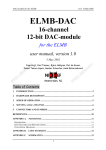
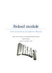
The PLC (SIEMENS S7) of the MVD cooling system does not have an interface to connect
it directly to a CAN-bus. But it does have an RS232 interface, which is used to connect it to a
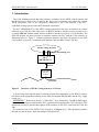
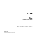
so-called SPICAN module which features an RS232 interface as well as a CAN interface. The
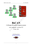
SPICAN module can thus provides an interface between the PLC and the CAN network, as
illustrated below in Figure 1. Custom application firmware has been developed for the SPICAN module to provide a communication interface between RS232 and CAN-bus.
MVD Cooling System
digital and analog I/O
PLC
(SIEMENS S7)
RS232
PLC-CAN
(SPICANmodule)
CAN-bus
Figure 1. Interface of MVD Cooling System to CAN-bus.
A protocol has been agreed upon for transfer of data and commands via the RS232 conne ction between the application running on the SPICAN module (PLC-CAN) and the PLC application (see "
APPENDIX C Protocol on the PLC-CAN↔PLC" for a description). The PLC-CAN application maps messages to and from the PLC application onto appropriate CAN-messages. This
document provides a detailed description of the interface to the PLC seen from the CAN-bus
side.
The protocol used on the MVD CAN-network is CANopen ([1]). This document assumes
that the user has at least a basic knowledge of this protocol.
2
ZEUS MVD PLC-CAN interface
v1.4 19-Feb-2001
2 Operation
The MVD-Controls Supervisor should be able to monitor the status of the MVD cooling system, to set a number of warning and error limits in the system and be able to assert general
control over the PLC (such as: start / stop / reinitialise). All communication will take place
using CAN-bus communication, i.e. the CANopen protocol, a standardized application layer
protocol for CAN-bus ([1]).
All relevant PLC parameters are mapped by PLC-CAN to an object in the CANopen Object
Dictionary (OD) in the “Manufacturer-Specific Profile Area”, shown in Table 3.
By making the parameters accessible for reading and writing through the CANopen SDO
(Service Data Object) mechanism and mapping appropriate parameters to CANopen PDOs
(Process Data Objects) a straightforward and CANopen-compliant interface to the cooling
system PLC has been created.
One of the PLC-CAN's features is that it can autonomously monitor the PLC for status
changes, which –if they occur– result in a CAN-message.
2.1
Initialisation
After power- up, watchdog reset, manual reset or CANopen initiated reset actions the PLCCAN node sends a so-called Bootup message (defined by the CANopen standard) as soon as it
has finished its initialization; this is a CAN-message with the following syntax:
PLC-CAN (NMT-Slave)
→
COB-ID
0x700 + Node_ID
Host (NMT-Master)
Byte 0
0
In case of a watchdog or manual reset the Bootup message is followed by a CANopen Emergency message, as listed in the table in section 2.8.
2.2
PLC Parameter Block
The PLC parameters accessible via the CAN-bus are listed under Object Dictionary object
0x2000 in Table 3. The descriptions of the parameters in this table speak for itself for most of
the parameters listed. Some of the parameters are read-only, others are read-write.
Some of the parameters require a more detailed description and/or subdivision into bits,
which is provided in the tables below.
3
ZEUS MVD PLC-CAN interface
♦
v1.4 19-Feb-2001
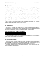
PLC Digital Inputs (OD index 0x2000, subindex 7)
§ in error-free situations all (used) bits are 1; unused bits are 0
§ all bits are read-only
BIT
0
1
2
3
4
5-15
Description (when bit=1)
Coolant flow OKAY
Pump temperature OKAY
24VDC powersupply OKAY
No pressure wave P1 detected
No pressure wave P2 detected
...Not used...
♦ PLC Error Input Override Setting (OD index 0x2000, subindex 41)
§ when set to 1 the corresponding error- input is ignored by the PLC application
§ all (used) bits are read-write; unused bits are 0
BIT
0
1
2
3
4
5-15
Description
Coolant flow
Pump temperature (clixon)
24VDC powersupply
Pressure wave P1
Pressure wave P2
...Not used...
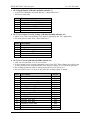
♦ PLC Error Status (OD index 0x2000, subindex 9)
§ only one error bit (bits 2-15) is set at a time
§ in case several errors occurred repeated resets of the PLC Error Status (by writing zero
to the OD object) are needed until the error status is cleared: Error bit (bit 0) goes to 0
§ the cooling system can only be started when the Error bit (bit 0) is 0
§ the interlock bit (bit 1) is set to 0 only after the cooling system is started
BIT
0
1
2
3
4
5
6
7
8
9
10
11
12
13
14
15
Description
Error ("OR" of errors present in PLC)
Interlock
Coolant flow
Coolant temperature (T1)
Pump temperature (clixon)
Humidity sensor (H1)
Humidity sensor (H3)
Pressure sensor (P1)
Pressure sensor (P2)
Airflow (AF)
24VDC powersupply
Pressure wave (P1)
Pressure wave (P2)
Humidity sensor (H2)
...Not used...
...Not used...
4
Access
RO
RO
RW
RW
RW
RW
RW
RW
RW
RW
RW
RW
RW
RW
RO
RO
ZEUS MVD PLC-CAN interface
v1.4 19-Feb-2001
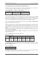
♦ PLC Warning Status (OD index 0x2000, subindex 10):
BIT
0
1
2
3
4
5
6
7
8
9
10
11
12
13
14
15
Description
Warning ("OR" of bits 1 to 15)
Coolant temperature (T1)
Pressure sensor (P1)
Pressure sensor (P2)
Humidity sensor (H1)
Humidity sensor (H3)
Airflow (AF)
Humidity sensor (H2)
...Not used...
...Not used...
...Not used...
...Not used...
...Not used...
...Not used...
Error in provided parameters
RS232 communication error
♦ PLC Global Status (OD index 0x2000, subindex 11):
§ When both bits 0 and 1 of this word are written as 1 the PLC switches to a so-called deventilation mode where the cooling system pump is running with all valves closed in order to expel any remaining air from the cooling liquid in the system.
♦
BIT
Description
0
1
2-15
Cooling system ON(1) or OFF(0)
Deventilate (when system ON (bit 0))
...Not used...
PLC Interlock Delay (OD index 0x2000, subindex 40)
§ The interlock delay is the time in seconds between the occurrence of an error condition
in the cooling system and the moment the hardware interlock intervenes and systems get
switched off or get taken into a safe state; this time allows other MVD control systems
to shut down gracefully or take appropriate actions before the interlock is activated or
even to prevent subsequent activation of the interlock.
5
ZEUS MVD PLC-CAN interface
2.3
v1.4 19-Feb-2001
Monitoring PLC Error, Warning and Global Statuses
Before PLC status and data monitoring can start the PLC-CAN node has to be set into Operational state using the following 2-databyte CANopen NMT message:
Host (NMT-Master) → PLC-CAN (NMT-Slave)
COB-ID
0x000
Byte 0
1
(Start_Remote_Node)
There is no reply to this message.
Byte 1
<Node-ID> or 0
(all nodes in ne twork)
PLC data that is subjected to regular monitoring can be read out using the CANopen PDO
mechanism. A PDO message is a non-confirmed CAN-message with one sender and one or
more receivers, containing no protocol overhead, only data (1 to 8 bytes). It is assumed that
receivers of a PDO message know the meaning of the data content of a PDO message.
PLC-CAN can produce 2 different PDOs, which we will call here PDO1 and PDO2. PDO2
messages are described in the next section.
The PLC parameters 'Error Status', 'Warning Status' and 'Global Status' are found in the
PLC parameter block in the Object Dictionary index 0x2000, subindices 9, 10 and 11. They
can be included in the regular 'monitoring scan' of the PLC parameters as described in the next
section.
However, to enable a more frequent check (or PLC-CAN autonomous check, see below) on
the PLC status words alone, an extra PDO has been defined that contains only these status
words (6 bytes in total): PDO1.
(The definition of the data content of PDO1 (its 'mapping') can be found in the Object Dictionary at index 0x1A00).
A PLC-CAN PDO1 CAN-message has 6 data bytes:
PLC-CAN
→
Host
Byte
0
0x180 +
Error
Node_ID
Status
(LSB)
COB-ID
1
Error
Status
(MSB)
2
Warning
Status
(LSB)
3
Warning
Status
(MSB)
4
Global
Status
(LSB)
5
Global
Status
(MSB)
This PDO1 message can be requested by the host by sending a socalled Remote Transmission Request (RTR) for PDO1. The CAN Remote Frame that constitutes the RTR has no data
bytes and looks like this:
Host
→
PLC-CAN
COB-ID
0x180+Node_ID
Typically the PLC-CAN status words would be read out every second for example, and the
PLC parameters from the previous section only every 30 seconds or so.
6
ZEUS MVD PLC-CAN interface
v1.4 19-Feb-2001
However, the preferred way is to set the PDO1 object to 'event-triggered', meaning that as
soon as PLC-CAN detects that one or more bits in the statuswords have changed it will send a
PDO1 message. To achieve this PLC-CAN polls the PLC periodically for its status words,
with a period that can be set in OD index 0x2002. This parameter is set in units of 100 ms: if
set to 1, PLC-CAN polls the PLC with a frequency of 10 Hz, when set to 2 with a frequency
of 5 Hz, when set to 10 with a frequency of 1 Hz, etc, etc, up to a maximum period of 25.5
seconds.
When OD index 0x2002 is set to 0, PLC-CAN does not poll the PLC statuswords and the
host should periodically issue an RTR for PDO1 as described above, if it want s to stay up-todate on the PLC statuswords.
Polling (and thus sending of event-triggered PDO1s) only takes place when PLC-CAN is in
Operational state (PLC-CAN state is controlled by CANopen NMT messages).
See "APPENDIX C Protocol on the PLC-CAN↔PLC RS232-connection" for more details
on PLC polling and the communication between PLC-CAN and PLC.
2.4
Monitoring PLC Parameters
PDO2 messages are used to transfer other PLC data that is to be monitored on a regular basis. The data to be mo nitored are16-bit data and are numbered according to the subindices of
PLC-CAN Object Dictionary index 0x2000 (Table 3). One PDO2 CAN-message is used to
transfer one 16-bit PLC-parameter preceeded by its Object Dictionary subindex. Thus every
'monitoring request' results in a series of PDO2 messages, one PDO2 for every PLCparameter to be monitored.
The number of parameters listed at OD index 0x2000 to be monitored (starting from subindex 1) can –if required– be set to any value by writing to OD index 0x2001 (using the CANopen SDO mechanism). This parameter has a default value of 6, but could be increased to e.g.
15 if additional PLC-parameters are added to OD index 0x2000 at subindices 12 to 15,
marked reserved. See Table 3.
A change to parameter 0x2001 can be made permanent by saving it to the PLC-CAN onboard non- volatile memory (see OD index 0x1010 in Table 1).
A PLC-CAN PDO2 CAN-message has 3 data bytes::
PLC-CAN → Host
COB-ID
Byte 0
0x280 +
PLC Parameter Index
Node_ID
Byte 1-2
16-bit PLC Parameter
with:
PLC Parameter Index: runs from 1 to 8 (or to whatever value has been set in OD index
0x2001).
PLC Parameter:
16-bits value, LSB in byte 1, MSB in byte 2.
(The definition of the data content of PDO2 (its 'mapping') can be found in the Object Dictionary at index 0x1A01).
A 'monitoring request' –as mentioned above– is either a SYNC message or an RTR (Remote
Transmission Request) for PDO2. Whether PLC-CAN responds to either one depends on the
configuration of its PDO2 transmission type (OD index 0x1801, subindex 2):
7
ZEUS MVD PLC-CAN interface
•
v1.4 19-Feb-2001
PDO2 transmission type = 1:
after every socalled SYNC message issued on the CAN-bus PLC-CAN sends 6 (or…)
PDO2 messages, one message for every PLC parameter configured for monitoring.
The SYNC message is a CAN-message with a fixed COB-ID and no data bytes:
Host
→
all (SYNC-)slave nodes
COB-ID
0x080
Note that all nodes configured to respond to a SYNC will react to a SYNC message.
•
PDO2 transmission type = 254:
after every socalled Remote Transmission Request (RTR) for PDO2 the node sends 8
PDO messages, one message for every PLC parameter configured for monitoring.
The CAN Remote Frame that constitutes the RTR has no data bytes and looks like this:
Host
→
PLC-CAN
COB-ID
0x280+Node_ID
Note that an RTR is sent to and received by only one particular node.
The PDO2 transmission type can also be saved to the PLC-CAN on-board non-volatile
memory if required (see section 2.7).
2.5
Setting PLC Error, Warning and Global Statuses
The PLC parameters 'Error Status', 'Warning Status' and 'Global Status' can be written to,
using the CANopen SDO mechanism.
'Error Status' and 'Warning Status' can be reset to zero by writing 0 to the corresponding OD
objects. To reset for example the 'Error Status' word the following CAN-message (SDO expedited transfer) is to be sent:
Host
→
PLC-CAN
Byte
COB-ID
0
0x600 +
0x2B
Node_ID
1
0x00
2
0x20
3
0x09
4
0x00
5
0x00
6-7
–
5
–
6-7
–
If successful PLC-CAN will reply with the following CAN- message:
PLC-CAN
COB-ID
0x580 +
Node_ID
→
Host
Byte
0
0x60
1
0x00
2
0x20
3
0x09
8
4
–
ZEUS MVD PLC-CAN interface
v1.4 19-Feb-2001
Note that in case several errors are present multiple resets of the 'Error Status' (by writing
zero to the OD object) are needed until the error status is cleared and the cooling system can
be started.
A similar command/reply message pair can be used to reset the 'Warning Status' word, or to
set or reset individual bits in the 'Global Status' PLC-parameter (if their function is defined,
see section 2.1).
SDO messages, to as well as from PLC-CAN, always contain 8 databytes and the mechanism to transfer data is 'SDO expedited transfer', meaning that the data is contained in the
message and is 4 bytes or less in size. (A segmented transfer would be necessary if the data to
be transferred contained more than 4 bytes). If for some reason a node cannot service an SDO
it will respond with an 'SDO Abort Domain Transfer' message (see example in section 2.7).
2.6
Setting PLC Error and Warning Limits
The PLC error and warning limits can be read and written by accessing the appropriate
subindices (16 to 47, see Table 3) of OD index 0x2000 using the CANopen SDO mechanism.
The values read and written are in ADC-counts. If physical values are required a conversion
from or to physical values has to be done by the user or the host application.
To set for example "P2 warning level minimum" (subindex 25 = 0x19 hexadecimal) to a
value of 10000 (0x2710 hexadecimal) the following CAN-message (SDO expedited transfer)
is to be sent:
Host
→
PLC-CAN
Byte
COB-ID
0
0x600 +
0x2B
Node_ID
1
0x00
2
0x20
3
0x19
4
0x10
5
0x27
6-7
–
5
–
6-7
–
If successful PLC-CAN will reply with the following CAN- message:
PLC-CAN
COB-ID
0x580 +
Node_ID
→
Host
Byte
0
0x60
1
0x00
2
0x20
3
0x19
4
–
To read for example "T error level maximum" (subindex 19 = 0x13 hexadecimal) the fo llowing CAN-message is to be sent:
Host
→
PLC-CAN
Byte
COB-ID
0
0x600 +
0x40
Node_ID
1
0x00
2
0x20
3
0x13
4
–
5
–
6-7
–
The reply CAN-message (SDO expedited transfer) of PLC-CAN looks for example like this:
9
ZEUS MVD PLC-CAN interface
PLCCAN
COB-ID
0x580 +
Node_ID
→
v1.4 19-Feb-2001
Host
Byte
0
0x4B
1
0x00
2
0x20
3
0x13
4
0x34
5
0x12
6-7
–
In this case it means that the "T error level maximum" (shown in bytes 4 and 5) is equal to
0x1234 (= 4660 decimal).
SDO messages, to as well as from PLC-CAN, always contain 8 databytes and the mechanism to transfer data is 'SDO expedited transfer', meaning that the data is contained in the
message and is 4 bytes or less in size. (A segmented transfer would be necessary if the data to
be transferred contains more than 4 bytes). If for some reason a node cannot service an SDO it
will respond with an 'SDO Abort Domain Transfer' message (see example in section 2.7).
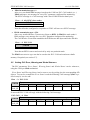
2.7
Storing PLC-CAN Parameters
Some parameters can be stored permanently onboard the PLC-CAN node in non-volatile
memory (an EEPROM) by writing the string "save" to OD index 0x1010. The CANopen SDO
mechanism is used to accomplish this:
Host
→
PLC-CAN
Byte
COB-ID
0
1
0x600 +
0x23
0x10
Node_ID
2
0x10
3
1
4
0x73
('s')
5
0x61
('a')
6
0x76
('v')
7
0x65
('e')
with OD index 0x1010 in byte 1+2 and subindex 1 in byte 3.
The parameters stored are:
§ OD index 0x1800, subindex 2 (PDO1 communication parameters).
§ OD index 0x1801, subindex 2 (PDO2 communication parameters).
§ OD index 0x2001 (number of PLC parameters to be monitored).
§ OD index 0x2002 (PLC status polling period).
PLC error and warning limit settings are assumed to be stored by the PLC on the PLC.
If the store-operation succeeded the controller sends the following reply:
PLC-CAN
COB-ID
0x580 +
Node_ID
→
Host
Byte
0
0x60
1
0x10
2
0x10
3
1
10
4
–
5
–
6-7
–
ZEUS MVD PLC-CAN interface
v1.4 19-Feb-2001
If the store-operation did NOT succeed the controller sends the following reply (SDO Abort
Domain Transfer, error reason: ‘hardware fault’ (for details see [1])):
PLC-CAN
COB-ID
0x580 +
Node_ID
→
Byte
0
0x80
Host
1
0x10
2
0x10
3
1
4
0
5
0
6
6
(Error Code)
7
6
(Error Class)
Parameters can be reset to their default values (by invalidating the corresponding contents of
the EEPROM) by writing to OD index 0x1011, using this time the string "load" in bytes 4 to 7
of the SDO message. Note that the default values take effect only after a subsequent reset of
the node. Default values are listed in the Object Dictionary tables.
11
ZEUS MVD PLC-CAN interface
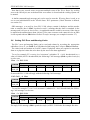
2.8
v1.4 19-Feb-2001
Emergency Objects
Emergency messages are triggered by the occurrence of an internal (fatal) error situation. An
emergency CAN- message has the following general syntax:
PLC-CAN → Host
COB-ID
Byte 0-1
0x080 +
Emergency
Node_ID
Error Code
Byte 2
Error Register
(Object 0x1001)
Byte 3-7
Manufacturer specific error field
The following Emergency messages are defined for PLC-CAN:
Emergency
Error Code
bit (Object 1001H)
(byte 0-1)
(byte 2)
Watchdog or
manual (frontpanel) reset
0x6000
0x01
Byte 3,4,5,6: Manufacturer Device Name
(Object Dictionary index 0x1008)
Byte 7: 0
CAN-controller
overrun: message lost
0x8100
0x10
CAN-controller
error:
communication
error
Local CAN
message buffer
overflow:
message lost
0x8100
0x10
0x8100
0x10
Byte 3: 1
Byte 4: counter (modulo 256)
Byte 5: CANSTA (CAN-controller status register)
Byte 6,7: 0
Byte 3: 2
Byte 4: counter (modulo 256)
Byte 5: CANSTA (CAN-controller status register)
Byte 6,7: 0
Byte 3: 3
Byte 4: counter (modulo 256)
Byte 5: CANSTA (CAN-controller status register)
Byte 6,7: 0
RS232:
communication
time-out
0xFF00
0x80
RS232:
unexpected
parameter index
0xFF00
0x80
RS232:
PLC poll operation aborted
0xFF00
0x80
EEPROM:
write failed
EEPROM: read
CRC error
0x5000
0x80
0x5000
0x80
Error
Description
Error Register
Manufacturer-specific Error Field
(byte 3-7)
Byte 3: 1
Byte 4: parameter index for which timeout occurred
Byte 5: number of received chars in RS232 buffer
Byte 6,7: 0
Byte 3: 2
Byte 4: parameter index expected
Byte 5: parameter index received
Byte 6,7: 0
Byte 3: 0x10
Byte 4: poll error counter
Byte 5,6,7: 0
Byte 3: 4
Byte 4,5,6,7: 0
Byte 3: 8
Byte 4,5,6,7: 0
Note that the Error Register (Object Dictionary index 0x1001) can have one or more of the
bits shown above set, depending on the node's history of error occurrences. The table shows
the Error Register bit that gets additionally set when described error occurs.
12
ZEUS MVD PLC-CAN interface
v1.4 19-Feb-2001
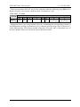
3 Object Dictionary
Table 1 to Table 4 show in detail the Object Dictionary (OD) of the PLC-CAN CANopen
application.
Column 'Attr' shows the access rights attribute of an object: RO=read-only, RW=read-orwrite, WO=write-only.
All entries in the OD are accessed using the CANopen SDO mechanism with expedited
transfer (object data content always <= 4 bytes).
Communication Profile Area (PLC-CAN)
Index
(hex)
Sub
Index
Name
Data/
Object
Attr
Default
(hex)
1000
1001
1002
1004
-
Device type
Error register
U32
U8
RO
RO
00000000
0
-
Manufacturer status reg
#PDOs supported
Total #PDOs supported
#PDOs sync
#PDOs async
U32
Array
U32
U32
U32
RO
0
RO
RO
RO
00000002
00000002
00000002
VisStr
VisStr
RO
RO
"SPIC"
"PC10"
U32
RO
= SPICAN module
MVD Cooling System
PLC-to-CAN, Version 1.0
set by frontpanel hex-switches
According to CANopen Predefined Connection Set
0 client, 1 server SDO
0
1
2
1008
100A
-
100B
-
Manufacturer device name
Manufacturer software
version
Node identifier
100E
-
Node Guarding COB-ID
U32
RO
100F
-
#SDOs supported
U32
RO
0x700+
Node-ID
00000001
0
1
Store parameters
Highest index supported
Save all parameters
Array
U8
U32
RO
RW
1
1
Restore default parameters
Array
Highest index supported
Restore all parameters
U8
U32
1010
1011
0
1
Comment
Error bits according to DS-301
(error status overview)
see below
0 receive, 2 transmit PDO
PDO after SYNC
PDO after RTR or 'event'
Save stuff in onboard EEPROM
read: 1
write "save": store all
Invalidate stuff in onboard
EEPROM
RO
RW
1
1
read: 1
write "load": invalidate all stored
Table 1. Communication Profile Area of the CANopen Object Dictionary.
13
ZEUS MVD PLC-CAN interface
v1.4 19-Feb-2001
Communication Profile Area (PLC-CAN) (continued…)
Index
(hex)
Sub
Index
Name
Data/
Object
Record
0
1
1st Transmit PDO parameters
Number of entries
COB-ID used by PDO
U8
U32
RO
RO
2
Transmission type
U8
RW
Record
0
1
2nd Transmit PDO parame ters
Number of entries
COB-ID used by PDO
U8
U32
RO
RO
2
Transmission type
U8
RW
2
280+
Node-ID
FE
1st Transmit PDO mapping
Number of entries
Cooling System Error
Status
Cooling System Warning
Status
Cooling System Global
Status
Record
U8
U32
RO
RO
3
20000910
U32
RO
20000A10
U32
RO
20000B10
0
1
2nd Transmit PDO mapping
Number of entries
Multiplexor 1
Record
U8
U32
RO
RO
2
6F100108
2
16-bit PLC parameter
U32
RO
2000FD10
1800
1801
1A00
0
1
2
3
1A01
Attr
Default
(hex)
Comment
Data type = PDOCommPar
2
180+
Node-ID
FE
According to CANopen Predefined Connection Set
254: (manufctr–specific) get PLC
statuswords at RTR (default)
1 : get PLC statuswords at
SYNC
Data type = PDOCommPar
According to CANopen Predefined Connection Set
254: (manufctr–specific) get PLC
data at RTR (default)
1 : get PLC data at SYNC
Data type = PDOMapping
OD-index 2000, sub-index 9;
Size = 16 bits
OD-index 2000, sub-index 10;
Size = 16 bits
OD-index 2000, sub-index 11;
Size = 16 bits
Data type = PDOMapping
OD-index 6F10, sub-index 1:
Multiplexor 1 (see DSP-404);
Size = 8 bits
OD-index 2000, sub-index 253:
PLC parameter via a mult iplexor;
Size = 16 bits
Table 2. Communication Profile Area of the CANopen Object Dictionary (continued).
The Manufacturer Status Register (Object Dictionary index 0x1002), a 32-bit object, providing more specific status information about the PLC-CAN module, i.e the type of errors that
have occurred (reported by Emergency Objects). The layout of this Register is as follows:
bits 31-5
bit 4
bit 3
bit 2
bit 1
bit 0
not used
PLC-status poll
operation
aborted (RS232)
PLC-CAN
EEPROM -read
CRC error
PLC-CAN
EEPROM -write
error
communication
timeout
(RS232)
unexpected
parameter index
received (RS232)
14
ZEUS MVD PLC-CAN interface
v1.4 19-Feb-2001
Manufacturer-specific Profile Area (PLC-CAN)
Index
(hex)
Sub
Index
Name
Data/
Object
Attr
Default
(dec)
0
1
2
3
4
5
6
7
8
PLC parameter block
Number of entries
Temperature
(T1)
Pressure 1
(P1)
Pressure 2
(P2)
Hygrometer 1
(H1)
Hygrometer 3
(H3)
Airflow
(AF)
Digital inputs
Hygrometer 2
(H2)
Array
U16
U16
U16
U16
U16
U16
U16
U16
U16
RO
RO
RO
RO
RO
RO
RO
RO
RO
53
9
10
11
Error status
Warning status
Global status
U16
U16
U16
RW
RW
RW
12
13
14
15
reserved
reserved
reserved
reserved
U16
U16
U16
U16
RO
RO
RO
RO
16
17
18
19
T1
T1
T1
T1
error level minimum
warning level min imum
warning level maximum
error level maximum
U16
U16
U16
U16
RW
RW
RW
RW
20
21
22
23
P1 error level minimum
P1 warning level min imum
P1 warning level maximum
P1 error level maximum
U16
U16
U16
U16
RW
RW
RW
RW
24
25
26
27
P2 error level minimum
P2 warning level minimum
P2 warning level maximum
P2 error level maximum
U16
U16
U16
U16
RW
RW
RW
RW
2000
Comment
see section 2.2
mapped into PDO1; see sect. 2.2
mapped into PDO1; see sect. 2.2
mapped into PDO1; see sect. 2.2
0
0
0
0
…continued in the next table…
Table 3. Manufacturer-specific Profile Area of the CANopen Object Dictionary for the PLC-CAN device.
15
ZEUS MVD PLC-CAN interface
v1.4 19-Feb-2001
Manufacturer-specific Profile Area (PLC-CAN) (continued…)
Index
(hex)
Sub
Index
Name
Data/
Object
Attr
Default
2000
Comment
..continued from previous table..
28
29
30
31
H1
H1
H1
H1
error level minimum
warning level minimum
warning level maximum
error level maximum
U16
U16
U16
U16
RW
RW
RW
RW
32
33
34
35
H3
H3
H3
H3
error level minimum
warning level minimum
warning level maximum
error level maximum
U16
U16
U16
U16
RW
RW
RW
RW
36
37
38
39
AF error level minimum
AF warning level minimum
AF warning level maximum
AF error level maximum
U16
U16
U16
U16
RW
RW
RW
RW
40
41
Interlock delay
Error input override
U16
U16
RW
RW
42
∆P1 error level maximum
U16
RW
43
∆P2 error level maximum
U16
RW
44
45
46
47
H2
H2
H2
H2
error level minimum
warning level minimum
warning level maximum
error level maximum
U16
U16
U16
U16
RW
RW
RW
RW
2001
Max. PLC monitoring subindex
for PDO2
U8
RW
8
2002
PLC-status polling period
for PDO1
U8
RW
0
in seconds [0, 200]
see section 2.2
Determines up to which subindex
of Object 2000 is to be monitored
using PDO2-RTR and/or SYNC
(Access to other subindices using
PDO1or SDO).
Time between consecutive polls
by PLC-CAN of PLC error and
warning status, in units of 100 ms;
'0' means: polling not enabled.
Table 4. Manufacturer-specific Profile Area of the CANopen Object Dictionary for the PLC-CAN device
(continued).
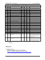
References
[1] H.Boterenbrood,
CANopen, high-level protocol for CAN-bus,
Version 3.0, NIKHEF, Amsterdam, March 20 2000.
(http://www.nikhef.nl/pub/departments/ct/po/doc/CANopen30.pdf).
16
ZEUS MVD PLC-CAN interface
v1.4 19-Feb-2001
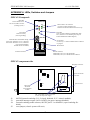
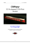
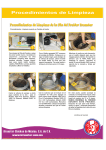
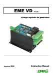
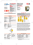
APPENDIX A LEDs, Switches and Jumpers
SPICAN Frontpanel:
Red LED:
CAN-controller error:
bus errors, buffer overflow
(message(s) lost!)
SPICAN
CAN
Green LEDs 'CAN' and 'SYS':
+5V power-supply indications for
CAN-bus driver and onboard electronics resp.
+5V
CAN
SYS
I/O
Red LED:
error occurred in RS232 communication with
PLC (check for received Emergency Objects
and/or Manufacturer Status Register)
Green LED:
CAN-bus activity
(receiving/sending)
Node-ID
Node-ID and CAN baudrate setting:
0x01-0x7F: Node-ID 1 to 127, 125 kbit/s
0x81-0xFF: Node-ID 1 to 127, 250 kbit/s
(top switch: high nibble,
bottom switch: low nibble)
o•
•
•
•
•
•
•
•
•
CAN
•
•
•
•
Green LED:
I/O activity, i.e. RS232 communication with PLC
in progress
Reset button
•
•
•
•
•
RS232
CAN-bus connector
RS232 connector;
4800 baud (8-N-1) for code downloads,
9600 baud (8-N-1) for communication with PLC
SN: 1
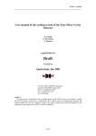
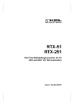
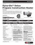
SPICAN component side:
backplane connector
: J5
::
J4 J3 1 :
: J1
3
Micro-key
20CN592
microcontroller
module
: J6
: J7
space for DC-DC
convertor
space for fuse
NB: wire-bridges in place as shown,
in case of local power-supply
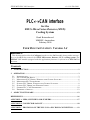
J1:
J3:
J4:
J5:
80C592 internal watchdog (J1/1-2 closed: disabled; J1/2-3 closed: enabled).
powerfail interrupt request via P1.0/#INT2 pin (open: interrupt disabled)
external watchdog enable selector, 80C592 pin P1.1 to MAX691 (open watchdog disabled).
reset jumper (closed: system will reset).
17
ZEUS MVD PLC-CAN interface
J6/J7: serial port signal connection/disconnection.
v1.4 19-Feb-2001
SPICAN solder side:
J9
J8
..
..
J13
..
J10
J11
Power options:
Local power supply:
..
..
via backplane
J8 + J9 closed, J10 + J11 open,
DC-DC convertor and fuse NOT placed, wire-bridges in place.
Ext. +5V power supply: via CAN-connector
J8 + J9 open, J10 + J11 closed,
DC-DC convertor NOT placed (wire-bridges in place), fuse placed.
Ext. +9…36V power-s.: via CAN-connector
J8 + J9 open, J10 + J11 closed,
DC-DC convertor and fuse placed.
Additional power option:
Battery backup:
J13 open.
APPENDIX B Connector Layout
9-pin D-sub male CAN-connector:
Pin
1
2
3
4
5
6
7
8
9
Signal
–
CAN_Low
V_gnd
–
–
–
CAN_High
–
V+
18
ZEUS MVD PLC-CAN interface
v1.4 19-Feb-2001
APPENDIX C Protocol on the PLC-CAN↔PLC RS232-connection
The cooling system's PLC works autonomously and independently but can be controlled and
monitored via its interface to the CAN-bus, formed by the PLC-CAN module and an RS232
connection between the PLC and the PLC-CAN. The RS232-connection is set to 9600 baud, 8
bits, 1 stop bit, no parity.
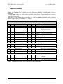
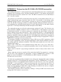
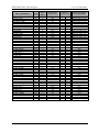
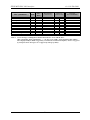
The protocol over the RS232-connection between the PLC-CAN module and the PLC is a
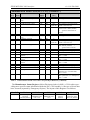
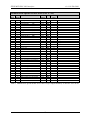
simple command/reply type of protocol where the PLC-CAN module is the initiator of the
command message: the PLC only generates a message in reply to a message from the PLCCAN. The full list of messages is shown in Table 5 (together with the preferred CANopen access mechanism for each individual parameter; for more details of this, see the tables containing the PLC-CAN Object Dictionary and the description of the PDOs).
The command message as well as the reply message consists of 3 bytes. The first byte contains a parameter- identifier in bit 0 to 6; bit 7 is 1 when the PLC-CAN requests a write access
to the parameter and bit 7 is 0 when a read access is requested; the value of byte 0 of the reply
must be identical in the reply from the PLC. This is checked by the PLC-CAN application for
data that is subsequently put in a CANopen PDO message (before being put in the PDO the
parameter- identifier is removed). When the PLC-CAN application detects such a mismatch in
the parameter- identifier in the RS232 command and reply message an appropriate CANopen
EMERGENCY message is sent (see section 2.8).
The parameter identifier is not checked for CANopen SDO access of PLC parameters; in this
case it is the responsibility of the CAN host-application to check that the subindex of the object (which equals the 'parameter identifier') in the SDO-reply matches the one in the corresponding SDO-request.
Bytes 2 and 3 of the PLC-CAN command message either have a don’t-care value (PLCCAN requests a read access) or contain the parameter- value (16-bit, LSB first) to be written/set in the PLC.
Bytes 2 and 3 of the PLC reply message contains the current or newly written value of the
parameter.
When a time-out occurs on reception of the reply from the PLC in response to a message
from the PLC-CAN application an appropriate CANopen EMERGENCY message is sent
(again see section 2.8) and PLC-CAN reinitializes its RS232 interface and buffers.
The time-out is set to 100 ms.
If a time-out or parameter-index mismatch occur s during the automatic PLC-status scanning
operation of the PLC-CAN application the appropriate CANopen EMERGENCY is sent. The
scanning operation is not suspended until a total of 50 such errors in a row occur (currently
hardcoded…). A successful PLC-status scan decrements the error counter by one. This is to
prevent a possible endless stream of error message when the connection to the PLC is permanently lost. The aborting of further PLC-status scanning is notified to the user by a separate
CANopen EMERGENCY (again see section 2.8).
The scanning operation can be resumed by sending a CANopen NMT Start-Remote-Node
message (the error counter is reset to zero).
19
ZEUS MVD PLC-CAN interface
v1.4 19-Feb-2001
Temperature (T)
Pressure 1 (P1)
Pressure 2 (P2)
Hygrometer 1 (H1)
Hygrometer 3 (H3)
Airflow (AF)
Digital Inputs
Hygrometer 2 (H2)
Error Status
“ (reset 1 e rror)
Warning Status
“
(reset warnings)
Global Status
“
(cooling on/off)
“
(deventilate on/off)
….reserved….
RO
RO
RO
RO
RO
RO
RO
RO
R
W
R
W
R
W
W
Byte1
bit 7
(R/W)
0
0
0
0
0
0
0
0
0
1
0
1
0
1
1
T1 min. error
“ “ “
(set)
T1 min. warning
T1 max. warning
T1 max. error
R
W
RW
RW
RW
P1 min. error
P1 min. warning
P1 max. warning
P1 max. error
PLC parameter
Attr
Byte1 bit 6-0
(parameter-id)
Byte 2+3
(parameter-data)
(preferred) CANopen
access mechanism
0x01
0x02
0x03
0x04
0x05
0x06
0x07
0x08
0x09
“
0x0A
“
0x0B
“
“
0x0C-0x0F
–
–
–
–
–
–
–
–
–
0
–
0
–
1/0
3/0
–
–
–
–
–
–
–
–
–
–
0
–
0
–
0
0
–
PDO2-Tx (RTR or SYNC)
PDO2-Tx (RTR or SYNC)
PDO2-Tx (RTR or SYNC)
PDO2-Tx (RTR or SYNC)
PDO2-Tx (RTR or SYNC)
PDO2-Tx (RTR or SYNC)
PDO2-Tx (RTR or SYNC)
PDO2-Tx (RTR or SYNC)
PDO1-Tx (RTR or CoS)
SDO
PDO1-Tx (RTR or CoS)
SDO
PDO1-Tx (RTR or CoS)
SDO
SDO
–
0
1
0/1
0/1
0/1
0x10
“
0x11
0x12
0x13
–
LSB
"
"
"
–
MSB
"
"
"
SDO
SDO
SDO
SDO
SDO
RW
RW
RW
RW
0/1
0/1
0/1
0/1
0x14
0x15
0x16
0x17
"
"
"
"
"
"
"
"
SDO
SDO
SDO
SDO
P2 min. error
P2 min. warning
P2 max. warning
P2 max. error
RW
RW
RW
RW
0/1
0/1
0/1
0/1
0x18
0x19
0x1A
0x1B
"
"
"
"
"
"
"
"
SDO
SDO
SDO
SDO
H1 min. error
H1 min. warning
H1 max. warning
H1 max. error
RW
RW
RW
RW
0/1
0/1
0/1
0/1
0x1C
0x1D
0x1E
0x1F
"
"
"
"
"
"
"
"
SDO
SDO
SDO
SDO
H3 min. error
H3 min. warning
H3 max. warning
H3 max. error
RW
RW
RW
RW
0/1
0/1
0/1
0/1
0x20
0x21
0x22
0x23
"
"
"
"
"
"
"
"
SDO
SDO
SDO
SDO
AF min. error
AF min. warning
AF max. warning
AF max. error
RW
RW
RW
RW
0/1
0/1
0/1
0/1
0x24
0x25
0x26
0x27
"
"
"
"
"
"
"
"
SDO
SDO
SDO
SDO
continued on next page
20
ZEUS MVD PLC-CAN interface
v1.4 19-Feb-2001
Attr
Byte1
bit 7
(R/W)
Byte1 bit 6-0
(parameter-id)
Interlock delay
Error Input Override
RW
RW
0/1
0/1
0x28
0x29
"
"
"
"
SDO
SDO
delta-P1 max. error
RW
0/1
0x2A
"
"
SDO
delta-P2 max. error
RW
0/1
0x2B
"
"
SDO
H2 min. error
H2 min. warning
H2 max. warning
H2 max. error
RW
RW
RW
RW
0/1
0/1
0/1
0/1
0x2C
0x2D
0x2E
0x2F
"
"
"
"
"
"
"
"
SDO
SDO
SDO
SDO
PLC parameter
Byte 2+3
(parameter-data)
CANopen
access mechanism
Table 5. List of messages exchanged over RS232 between PLC-CAN and the PLC.
(RO = Read-Only, RW = Read/Write, ‘–‘ = 0 / don’t care, LSB = Least Significant Byte, MSB =
Most Significant Byte; RTR = triggered by CAN Remote Transmission Request, SYNC = triggered
by CANopen SYNC message, CoS = triggered by Change of State).
21