1
FLIGHT MANUAL
FOR
A SAILPLANE
SZD-56-2 "Diana - 2"
Model:
Serial No:
..........................
Registration:
..........................
Issue I, March 2006
Pages identified by „Appr.” are approved by:
On behalf of President
of Civil Aviation Office
Signature:
Stamp:
Original date of approval:
March 1,, 2006
This sailplane is to be operated in compliance with information and limitations
contained herein. This manual should be always stored onboard.
This is translation of the original Polish document agreed with airworthiness Authority
Translated by:
Tadeusz Zboś
Biuro Projektowe „B”
Bogumił Bereś
SECTION 0
ISSUANCES
FLIGHT MANUAL
SZD-56-2 „Diana-2”
SECTION 0
0.
ISSUANCES
0.1. Record of revisions
0.2
0.2. List of effective pages
0.3
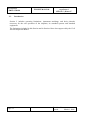
0.3. Table of contents
0.4
0.4. Table of figures
0.5
Revision No
Issued:
March 1, 2006
page 0.1
SECTION 0
ISSUANCES
Biuro Projektowe „B”
Bogumił Bereś
FLIGHT MANUAL
SZD-56-2 „Diana-2”
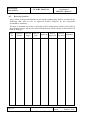
0.1. Record of revisions
Any revision of the present Manual, except actual weighing data, must be recorded in the
following table and in case of approved Section endorsed by the responsible
airworthiness Authority.
The new or amended text in the revised page will be indicated by a black vertical line in
the left hand margin, and the Revision No and the date will be shown on the bottom left
hand of the page.
Rev.
No
page 0.2
Affected
Section
Affected
Page
Date of
Date of
Approval
Issue
Approval
Date of
Insertion
Signature
Revision No
Issued:
March 1, 2006
Biuro Projektowe „B”
Bogumił Bereś
SECTION 0
ISSUANCES
FLIGHT MANUAL
SZD-56-2 „Diana-2”
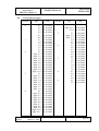
0.2.
List of effective pages
Section
0
1
2
3
4
Page
Date
0.1
0.2
0.3
0.4
01.03.2006
01.03.2006
01.03.2006
01.03.2006
0.5
0.6
1.1
1.2
1.3
1.4
1.5
1.6
2.1
Appr. 2.2
Appr. 2.3
Appr. 2.4
Appr. 2.5
Appr. 2.6
Appr. 2.7
Appr. 2.8
Appr. 2.9
Appr. 2.10
3.1
Appr. 3.2
Appr. 3.3
Appr. 3.4
Appr. 3.5
Appr. 3.6
Appr. 3.7
Appr. 3.8
4.1
Appr. 4.2
Appr. 4.3
Appr. 4.4
Appr. 4.5
Appr. 4.6
Appr. 4.7
Appr. 4.8
Appr. 4.9
Appr. 4.10
Appr. 4.11
01.03.2006
01.03.2006
01.03.2006
01.03.2006
01.03.2006
01.03.2006
01.03.2006
01.03.2006
01.03.2006
01.03.2006
01.03.2006
01.03.2006
01.03.2006
01.03.2006
01.03.2006
01.03.2006
01.03.2006
01.03.2006
01.03.2006
01.03.2006
01.03.2006
01.03.2006
01.03.2006
01.03.2006
01.03.2006
01.03.2006
01.03.2006
01.03.2006
01.03.2006
01.03.2006
01.03.2006
01.03.2006
01.03.2006
01.03.2006
01.03.2006
01.03.2006
01.03.2006
Revision No
Issued:
March 1, 2006
Section
5
6
7
8
9
Page
Date
Appr. 4.12
01.03.2006
Appr. 4.13
4.14
01.03.2006
01.03.2006
5.1
Appr. 5.2
Appr. 5.3
5.4
5.5
5.6
6.1
6.2
6.3
6.4
6.5
6.6
7.1
7.2
7.3
7.4
7.5
7.6
8.1
8.2
8.3
8.4
9.1
9.2
01.03.2006
01.03.2006
01.03.2006
01.03.2006
01.03.2006
01.03.2006
01.03.2006
01.03.2006
01.03.2006
01.03.2006
01.03.2006
01.03.2006
01.03.2006
01.03.2006
01.03.2006
01.03.2006
01.03.2006
01.03.2006
01.03.2006
01.03.2006
01.03.2006
01.03.2006
01.03.2006
01.03.2006
page 0.3
SECTION 0
ISSUANCES
0.3.
Biuro Projektowe „B”
Bogumił Bereś
FLIGHT MANUAL
SZD-56-2 „Diana-2”
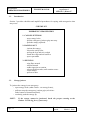
Table of contents
0.
ISSUANCES (a non-approved section)
1.
GENERAL (a non-approved section)
2.
LIMITATIONS (an approved section)
3.
EMERGENCY PROCEDURES (an approved section)
4.
NORMAL PROCEDURES (an approved section)
5.
PERFORMANCES (a partly approved section)
6.
WEIGHT AND BALANCE (a non-approved section)
7.
SAILPLANE AND SYSTEMS DESCRIPTION (a non-approved section)
8.
SAILPLANE HANDLING, CARE AND MAINTENANCE
(a non-approved section)
9.
SUPPLEMENTS
page 0.4
Revision No
Issued:
March 1, 2006
Biuro Projektowe „B”
Bogumił Bereś
SZD-56-2 „Diana-2”
0.4.
FLIGHT MANUAL
SECTION 0
ISSUANCES
Table of figures
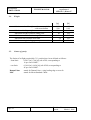
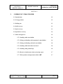
Fig. 1/1 Three-view drawing ........................................................................................... 1.5
Fig. 2/1 Airspeed indicator marking ................................................................................ 2.5
Fig. 2/2 Allowed C.G. range at different empty weights................................................. 2.6
Fig. 4/1 Wing rigging ...................................................................................................... 4.3
Fig. 4/2 Tailplane rigging ................................................................................................ 4.4
Fig. 5/1 IAS Calibration ................................................................................................. 5.2
Fig. 5/2 Polar speed (calculated) .................................................................................... 5.5
Fig. 5/3 Data on optimum use of wing flap ..................................................................... 5.7
Fig. 7/1 Scheme of board instrument system.................................................................. 7.3
Fig. 7/2 Cockpit view ...................................................................................................... 7.4
Revision No
Issued:
March 1, 2006
page 0.5
SECTION 0
ISSUANCES
FLIGHT MANUAL
Biuro Projektowe „B”
Bogumił Bereś
SZD-56-2 „Diana-2”
Intentionally left blank
page 0.6
Revision No
Issued:
March 1, 2006
Biuro Projektowe „B”
Bogumił Bereś
SECTION 1
GENERAL
FLIGHT MANUAL
SZD-56-2 „Diana-2”
SECTION 1
1.
GENERAL
1.1. Introduction
1.2
1.2. Certification basis
1.2
1.3. Warnings, cautions and notes
1.2
1.4. Descriptive and technical data
1.3
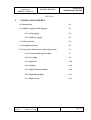
1.5. Three-view drawing
1.5
Revision No
Issued:
March 1, 2006
page 1.1
SECTION 1
GENERAL
1.1.
FLIGHT MANUAL
Biuro Projektowe „B”
Bogumił Bereś
SZD-56-2 „Diana-2”
Introduction
The sailplane Flight Manual has been prepared to provide pilots and instructors with
information for safe and efficient operation of the SZD-56-2 "Diana-2" sailplane.
This manual includes the information required to be furnished to the pilot by JAR-22
requirements. It also contains supplemental data supplied by the sailplane manufacturer.
1.2.
Certification basis
This type of sailplane, designated SZD-56-2 "Diana-2" has been approved for operation
by the Polish airworthiness Authority (Civil Aircraft Inspection Board) in accordance
with Joint Airworthiness Requirements for Sailplanes and Powered Sailplanes JAR-22,
Amendment 7 of 1 September 2003, and gained Type Certificate No BG 203/1.
Category of Airworthiness:
1.3.
Utility.
Warnings, cautions and notes
The warnings, cautions and notes used in the Flight Manual are defined as follows:
WARNING:
means that non-observation of the corresponding procedure leads to
an immediate or important degradation of the flight safety.
CAUTION:
means that non-observation of the corresponding procedure leads to
a minor or to a more or less long term degradation of the flight safety.
NOTE:
page 1.2
draws the attention on any special item not directly related to safety
but which is important or unusual.
Revision No
Issued:
March 1, 2006
Biuro Projektowe „B”
Bogumił Bereś
FLIGHT MANUAL
SZD-56-2 „Diana-2”
1.4.
SECTION 1
GENERAL
Descriptive and technical data
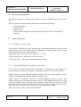
SZD-56-2 “Diana-2” is a single seat, high performance sailplane intended for FAI 15meter Class. Thanks to its high performances, “Diana-2” is especially suitable for
competition flying.
Sailplane constructed of carbon / aramide / epoxy composites, with sandwich structures
employing hard PVC foam core.
Monocoque structure fuselage of characteristic silhouette, aft of the cockpit area passing
in a small diameter tube. Over the wing portion, the fuselage spar ends are protruding out
from the fuselage.
Two-panel wing of multi-tapered outline employs the airfoil family, from KL-002128F/17 at the root onto KL-002-122F/17 at the tip. Detachable winglets based on the
distinct airfoil family. Wing structure in multicell, monocoque torque box layout. Air
brake extending on wing top surface only. Flaperon of 0.17 chord ratio over the whole
wing span. On flaperon bottom surface, the pneumatic turbulizers are provided, supplied
from NACA air-intakes. Each wing panel contains two integral ballast tanks with
independent jettison valves. Total capacity of wing tanks ranges 248[litre] (65.5[gal]).
Wing / fuselage connection is accomplished by shoving the wing panels on the fuselage
spar ends, and locking these with two bolts parallel to wing chord. The air brake control
systems, and water tank valves actuation connected automatically {at wing rigging),
while coupling in flaperon control system - by means of joint secured with sleeve.
Horizontal tailplane in „T” arrangement mounted on a fin with horizontal, mechanically
locked bolt. Elevator control coupling by means of joint with locking sleeve. In a fin the
antenna for board transceiver is provided. At fin root, a water ballast tank of 5.6[litre]
(1.48[gal]) capacity is installed.
The sprung, retractable landing gear equipped with the TOST AERO 4.00 x 4, 300mm
diameter wheel, and drum brake. Tail wheel of 100mm diameter with polyurethane tread.
Tow release installed on a fuselage bottom, front part.
One piece, front-hinged, upwards opening cockpit canopy, closed with two grips on
canopy frame. Emergency jettison accomplished by opening the canopy locks and
pulling onto stop the red grip at the base of instrument panel, followed by pushing the
canopy upwards.
Control stick on the right hand cockpit side. Mushroom type instrument panel.
The correct pilot’s attitude in a cockpit set by means of the on-ground adjustable back
rest with adjustable head rest, or head rest only, supplemented with the in-flight
adjustable pedals.
Due to cockpit arrangement, a pilot higher than 180 cm may find the position in a cockpit
with removed back rest more comfortable. In such case, pilot leans his back against
wheel house wall, and the head against head-rest – this latter constituting optional
equipment of the sailplane.
Revision No
Issued:
March 1, 2006
page 1.3
SECTION 1
GENERAL
FLIGHT MANUAL
Biuro Projektowe „B”
Bogumił Bereś
SZD-56-2 „Diana-2”
Effective cockpit ventilation is ensured by the nose air intake with control valve, side
blow with air stream direction-, and intensity control, as well as by the side slide window
with deflectable ventilation tab.
Control systems of elevator, rudder, flaperon and air brake - push-rod type. Longitudinal
trim control - spring type. Tow release and wheel brake control - cable type.
TECHNICAL DATA:
Span
15.00
[m]
49.21
[ft]
Length
6.88
[m]
22.57
[ft]
Height (fin with tail wheel)
1.35
[m]
4.43
[ft]
Wing profile
KL-002-128F/17 at wing root,
through KL-002-122F/17 at tip
Root chord
0.712
[m]
2.33
[ft]
Mean Standard Chord
0.615
[m]
2.02
[ft]
Wing area
8.64
[sqm]
93.0
[sqft]
Aspect ratio
26.04
Dihedral
2
[deg]
Tailplane span
2.50
[m]
8.20
[ft]
Empty weight (approx.)
182
[kg]
401
[lb]
All-up -without water ballast
mass: -with water ballast
297
[kg]
655
[lb]
500
[kg]
1102
[lb]
Maximum cockpit load
115
[kg]
253
[lb]
Wing surface
loading:
page 1.4
-maximum
57.87
[kg/sqm]
11.85
[lb/sqft]
-minimum
27.43
[kg/sqm]
5.62
[lb/sqft]
Revision No
Issued:
March 1, 2006
Biuro Projektowe „B”
Bogumił Bereś
FLIGHT MANUAL
SZD-56-2 „Diana-2”
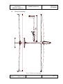
1.5.
SECTION 1
GENERAL
Three-view drawing
Fig. 1/1 Three-view drawing
Revision No
Issued:
March 1, 2006
page 1.5
SECTION 1
GENERAL
FLIGHT MANUAL
Biuro Projektowe „B”
Bogumił Bereś
SZD-56-2 „Diana-2”
Intentionally left blank
page 1.6
Revision No
Issued:
March 1, 2006
Biuro Projektowe „B”
Bogumił Bereś
SECTION 2
LIMITATIONS
FLIGHT MANUAL
SZD-56-2 „Diana-2”
SECTION 2
2.
LIMITATIONS
2.1. Introduction
2.2
2.2. Airspeed
2.3
2.3. Airspeed indicator markings
2.4
2.4. Weight
2.6
2.5. Centre of gravity
2.6
2.6. Approved manoeuvres
2.8
2.7. Manoeuvring load factors
2.8
2.8. Flight crew
2.8
2.9. Kinds of operation
2.9
2.10. Minimum equipment
2.9
2.11. Aerotow
2.9
2.12. Other limitations
2.9
2.13. Limitations placard
2.10
Revision No
Issued:
March 1, 2006
page 2.1
SECTION 2
LIMITATIONS
2.1.
FLIGHT MANUAL
Biuro Projektowe „B”
Bogumił Bereś
SZD-56-2 „Diana-2”
Introduction
Section 2 includes operating limitations, instrument markings, and basic placards
necessary for the safe operation of the sailplane, its standard systems and standard
equipment.
The limitations included in this Section and in Section 9 have been approved by the Civil
Aircraft Inspection Board.
page 2.2
Revision No
Issued:
March 1, 2006
Biuro Projektowe „B”
Bogumił Bereś
SECTION 2
LIMITATIONS
FLIGHT MANUAL
SZD-56-2 „Diana-2”
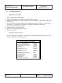
2.2.
Airspeed
Airspeed limitations and their operational significance are shown below:
IAS
[km/h ]
IAS
[kt]
VNE Never exceed speed
277
149
Do not exceed this speed in any
operation and do not use more than
1/3 of control deflection.
VRA Rough air speed
198
107
Do not exceed this speed except in
smooth air, and then only with
caution.
Examples of rough air are lee-wave
rotor, thunderclouds etc.
VA Manoeuvring speed
198
107
Do not make full or abrupt control
movement above this speed, because
under certain conditions the
sailplane may be overstressed by
full control movement.
Speed
VFE Maximum
flap extended speed:
Remarks
Do not exceed these speeds with the
given flap setting.
-2°
277
149
0°
277
149
+8°
277
149
+14°
224
121
+28o
224
121
VT Maximum
aerotowing speed
139
75
Do not exceed this speed during
aerotowing.
VLO Maximum landing
gear operating speed
200
108
Do not extend or retract the landing
gear above this speed.
Revision No
Issued:
March 1, 2006
page 2.3
SECTION 2
LIMITATIONS
Biuro Projektowe „B”
Bogumił Bereś
FLIGHT MANUAL
SZD-56-2 „Diana-2”
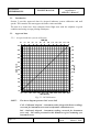
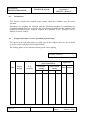
In the following table the allowed VNE values for various flight altitudes are given:
!!!
Absolute flight altitude
[km]
0÷2
3
4
5
6
8
10
IAS [km/h]
277
264
249
236
224
200
177
Absolute flight altitude
[1000 ft]
0÷6.6
9.8
13.1
16.4
19.7
26.3
32.8
IAS [kt]
149
142
134
127
121
108
96
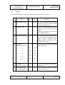
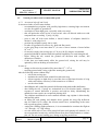
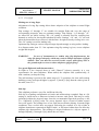
2.3.
Airspeed indicator markings
Airspeed indicator markings and their colour-code significance are shown below:
Marking
(IAS) value or range
[km/h]
[kt]
Significance
White arc
92 ÷ 224
50 ÷121
Positive flap operating range.
(Lower limit is 1.1VS0 in landing
configuration at maximum weight;
upper limit is maximum speed
permissible with flaps extended
positive.)
Green arc
111 ÷ 198
60÷107
Normal operating range.
(Lower limit is 1.1VS1 at maximum
weight and most forward C.G. with
flaps
neutral;
upper limit is rough air speed.)
Yellow arc
198 ÷ 277
107÷149
Manoeuvres must be conducted
with caution and only in smooth air.
radial Red
line
277
149
Maximum speed for all operations.
Yellow
triangle
94
51
Approach speed at maximum weight
without water ballast.
VS1 = glider stalling speed in a given flight configuration,
VS0 = stalling speed in a landing configuration, at maximum weight and most forward
C.G. position
page 2.4
Revision No
Issued:
March 1, 2006
Biuro Projektowe „B”
Bogumił Bereś
SECTION 2
LIMITATIONS
FLIGHT MANUAL
SZD-56-2 „Diana-2”
100
winter
80
60
120
km/h
300
250
150
200
40
20
100
80
120
140
knots
60
160
40
winter
white
green
yellow
red
yellow
Fig. 2/1 Airspeed indicator marking
Revision No
Issued:
March 1, 2006
page 2.5
SECTION 2
LIMITATIONS
2.4.
FLIGHT MANUAL
SZD-56-2 „Diana-2”
Weight
Maximum take-off weight: -without water ballast
-with water ballast
Maximum landing weight
Maximum weight of all non-lifting parts
Maximum water ballast in wing tanks
Maximum water ballast in tail tank
Maximum weight in baggage compartment
2.5.
Biuro Projektowe „B”
Bogumił Bereś
[kg]
[lb]
297
500
500
90
248
5.6
5.0
655
1102
1102
198
547
12.3
11
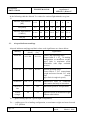
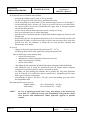
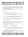
Centre of gravity
The limits of in flight permissible C.G. position have been defined as follows:
- front limit
0.2017 [m] (7.94 [in]) aft of DP, corresponding to
19 per cent of MSC,
- rear limit
0.3618 [m] (14.24 [in]) aft of DP, corresponding to
45 per cent of MSC.
Datum Point
MSC
stands for Datum Point = wing leading edge at root rib.
stands for Mean Standard Chord.
page 2.6
Revision No
Issued:
March 1, 2006
Biuro Projektowe „B”
Bogumił Bereś
SECTION 2
LIMITATIONS
FLIGHT MANUAL
SZD-56-2 „Diana-2”
63
X [cm]
61
59
57
55
175
180
185
190
195
mM [kg]
25.0
24.5
X [in]
24.0
23.5
23.0
22.5
22.0
21.5
385
395
405
415
425
mM [lb]
Fig. 2/2 Allowed C.G. range at different empty weights
mM - empty weight, X - empty sailplane C.G.
Example of C.G. position calculation is given in Section 4, Technical Service Manual of
SZD-56-2 “Diana-2”.
Revision No
Issued:
March 1, 2006
page 2.7
SECTION 2
LIMITATIONS
2.6.
FLIGHT MANUAL
Biuro Projektowe „B”
Bogumił Bereś
SZD-56-2 „Diana-2”
Approved manoeuvres
This sailplane has been certified in „Utility” Category, with no aerobatic manoeuvres
allowed.
2.7.
Manoeuvring load factors
The allowed manoeuvring load factors are as follows:
at VA = 198[km/h] at VNE =277[km/h]
(107 [kt])
(149 [kt])
maximum positive load factor
+ 5.3
+ 4.0
maximum negative load factor
-2.65
- 1.5
NOTE:
The above refers to the configuration with air brake retracted,
and wing flap setting not exceeding +8o.
With air brake extended, the positive limit manoeuvring load factor is +3.5, over the
whole range of operating airspeed.
With wing flaps deflected down by more than +8o, the positive limit manoeuvring load
factor is +4.0, over the airspeed range up to VFE = 224[km/h] (121[kt])
2.8.
Flight crew
The pilot + parachute weight must be contained within the following limits:
- minimum
- maximum
page 2.8
55 [kg] (121 [lb]),
110 [kg] (242 [lb]).
Revision No
Issued:
March 1, 2006
Biuro Projektowe „B”
Bogumił Bereś
FLIGHT MANUAL
SZD-56-2 „Diana-2”
2.9.
SECTION 2
LIMITATIONS
Kinds of operation
This sailplane has been certified in „Utility” Category and is intended for normal soaring
flight in accordance with VFR rules, by day.
WARNING: The following are forbidden:
- night flying,
- cloud flying,
- aerobatics.
2.10. Minimum equipment
The minimum equipment required according to JAR-22 standards comprises:
− airspeed indicator
− altimeter,
− pilot safety harness (4-point).
Sailplane standard equipment, apart from the listed above, contains:
− variometer
±5 [m/s] (±10 [kt]),
− compensator of total energy variometer,
− compass,
− first aid kit.
2.11. Aerotow
The maximum allowed aerotowing speed is as follows:
VT =139 [km/h] (75 [kt]).
The towing rope shall be equipped with the weak link of rated strength:
690 [kg] ±10% (1520 [lb] ±10%).
For aerotow, the length of tow rope must be at least:
30 [m] (98 [ft]).
2.12. Other limitations
WARNING: This sailplane is not adapted for winch-launched take off.
WARNING: Flying with water ballast at ambient temperature below 0oC forbidden
Revision No
Issued:
March 1, 2006
page 2.9
SECTION 2
LIMITATIONS
Biuro Projektowe „B”
Bogumił Bereś
FLIGHT MANUAL
SZD-56-2 „Diana-2”
2.13. Limitations placard
This placard is located on the right hand cockpit wall.
OPERATING LIMITATIONS
Weight:
Empty weight
Maximum in flight weight:
-with water ballast
-without water ballast
Cockpit load:
- maximum
- minimum
[kg] Airspeed IAS :
182
VNE
VA
500
VRA
297
VT
VLO
115
VFE +28o÷+8o
55
VFE +8o ÷ -2o
[km/h
]
277
198
198
139
200
224
277
OPERATING LIMITATIONS
Weight:
Empty weight
Maximum in flight weight:
-with water ballast
-without water ballast
Cockpit load:
- maximum
- minimum
NOTE:
page 2.10
[lb] Airspeed IAS :
401
VNE
VA
1102
VRA
655
VT
VLO
253
VFE +28o÷+8o
121
VFE +8o ÷ -2o
[kt]
149
107
107
75
108
121
150
Further placards - see Technical Service Manual.
Revision No
Issued:
March 1, 2006
Biuro Projektowe „B”
Bogumił Bereś
FLIGHT MANUAL
SZD-56-2 „Diana-2”
SECTION 3
EMERGENCY PROCEDURES
SECTION 3
3.
EMERGENCY PROCEDURES
3.1. Introduction
3.2
3.2. Canopy jettison
3.2
3.3. Bailing out
3.3
3.4. Stall recovery
3.3
3.5. Spin recovery
3.3
3.6. Spiral dive recovery
3.4
3.7. Other emergencies
3.4
3.7.1. Landing with water ballast
3.4
3.7.2. Flying and landing with asymmetric water ballast
3.4
3.7.3. Flying and landing with tail water ballast
3.6
3.7.4. Landing with main wheel retracted
3.6
3.7.5. Landing with ground loop
3.6
3.7.6. Break, or inadvertent release of towing ropee
3.7
3.7.7. Water jettison at temperatures below 0° C
3.7
Revision No
Issued:
March 1, 2006
page 3.1
SECTION 3
EMERGENCY PROCEDURES
3.1.
Biuro Projektowe „B”
Bogumił Bereś
FLIGHT MANUAL
SZD-56-2 „Diana-2”
Introduction
Section 3 provides checklist and amplified procedures for coping with emergencies that
may occur.
CHECKLIST
EMERGENCY PROCEDURES
1. CANOPY JETTISON
- open canopy locks
- pull the emergency jettison grip onto stop
- push the canopy upwards
2. BAILING OUT
- jettison the canopy
- release the safety belts
- pull up the legs and exit cockpit
- watch the wings and tail surfaces
- open a parachute
3. SPINNING
- wing flaps neutral
- ailerons neutral
- rudder opposite to rotation
- release stick forwards, until rotation ceases
- center rudder
- pull out of dive
3.2.
Canopy jettison
To jettison the canopy in an emergency:
− open canopy locks (white colour - on canopy frame),
− pull onto stop the emergency jettison grip (red colour at the bottom of instrument panel),
− resolutely push the canopy up
NOTE:
page 3.2
If the canopy cannot be jettisoned, break the perspex starting at the
window. Use the leg force, if necessary.
Revision No
Issued:
March 1, 2006
Biuro Projektowe „B”
Bogumił Bereś
FLIGHT MANUAL
SZD-56-2 „Diana-2”
3.3.
SECTION 3
EMERGENCY PROCEDURES
Bailing out
Bailing out is the last resort, mandatory emergency action if it is not possible to control
the glider into the safe landing.
To bail out:
− jettison the canopy, acc. to item 3.2,
− release the safety belts,
− pull up the legs and bail out (if the glider is rotating e.g. spinning - bail out towards
rotation centre),
− open the parachute with a delay (depending on circumstances), acc. to its operation
instruction.
NOTE:
3.4.
If bailing out takes place below 200 [m] (656 [ft]) of altitude, the parachute
should be opened immediately after leaving the cockpit, avoiding (as far as
possible) collision with the glider.
Stall recovery
The stalled glider pitches nose down symmetrically, or with a tendency to bank.
The recovery is troubleless and reliable by “releasing” the stick forwards.
3.5.
Spin recovery
This sailplane is not allowed for spinning. Recovery from an inadvertent spin (this
concerns also sailplane with water ballast) should be accomplished as follow:
−
−
−
−
−
ailerons neutral,
wing flaps neutral,
rudder opposite to rotation
release stick forwards, until the rotation ceases
center the rudder, with simultaneous pulling out of ensuing dive
The recovery ensues without significant delay.
Revision No
Issued:
March 1, 2006
page 3.3
SECTION 3
EMERGENCY PROCEDURES
3.6.
Biuro Projektowe „B”
Bogumił Bereś
FLIGHT MANUAL
SZD-56-2 „Diana-2”
Recovery from spiral dive
Depending on aileron-, and wing flap position in a spin, sailplane can pass into spiral
dive.
Recovery from this flight condition should be accomplished as follows:
−
−
−
−
3.7.
wing flaps neutral,
ailerons neutral
rudder neutral
release the stick slightly forwards and gently pull out of dive, controlling the
airspeed
Other emergencies
3.7.1. Landing with water ballast
For the sake of landing gear loads, landing with water ballast should be restricted to the
indispensable cases (e.g. balked take-off, malfunction of ballast tanks valve control,
unsuccessful take-off for competition task).
Approach at speed raised by 10 ÷ 20 [km/h] (5 ÷ 11 [kt]).
Touch down with care, preferably on a paved runway.
Cross-wind, heavy- and pancake landing should be avoided.
3.7.2. Flight and landing with asymmetric water ballast
For the sake of design characteristics, appearance of asymmetric water ballast in a
normal operation, carried in accordance with sailplane manuals, is not much probable.
Slight asymmetry to wing ballast distribution remains, in general, imperceptible to a pilot
and does not significantly affect the flight or landing safety.
Higher degree of asymmetry results in a distinct sailplane tendency to bank. This
tendency depends on wing flaps setting and airspeed. With ballast tank full in one wing
panel, and empty in the second, the aileron opposite full deflection is necessary when
approaching the stall speed. At stall speed, there is a tendency to bank towards „heavy”
wing. The correct controls action will result in regaining the level flight.
Turns towards the „light” wing are recommended.
page 3.4
Revision No
Issued:
March 1, 2006
Biuro Projektowe „B”
Bogumił Bereś
FLIGHT MANUAL
SZD-56-2 „Diana-2”
SECTION 3
EMERGENCY PROCEDURES
Asymmetry can appear due to:
1. Water outflow on one side through the leaky valve in one wing. The asymmetry can
increase gradually until reaching the full / empty configuration of corresponding (front
or rear) wing tanks.
In case of increasing sailplane tendency to bank, the following procedure should be
employed:
−
−
−
−
−
open all discharge valves,
maintain the forced, slight bank of sailplane towards the „light” wing,
avoid sailplane stall, especially in turns towards the „heavy” wing,
change to lateral balance must be observed,
on regaining the correct lateral balance, discharging of the water ballast can be
stopped, and the flight task can be continued acc. to the program.
2. The lack of -, or restrained water outflow from one of wing tanks during water ballast
discharge.
When an increasing tendency to bank appears, after opening the valves, the following
should be observed:
− retard landing, if at all possible (resign the accelerated descent with air brake
extended), or even make use of ascending air current to climb,
− maintain the forced bank towards the „light” wing
− avoid sailplane stall, especially in turns towards the „heavy” wing,
− if, after approx. 10 minutes, the asymmetry ceases gradually - flight task can be
continued acc. to the program,
− if, after approx. 10 minutes, the asymmetry remains unchanged or is increasing
further - turn to the nearest airfield and report necessity of emergency landing.
Touch down to be accomplished with sailplane bank towards the „light” wing, at
raised speed and at a safe distance from obstacles on a „heavy” wing side. If, in
ground roll, sailplane will bank towards the „heavy” wing - immediately deflect the
rudder to the opposite side, and release the stick forwards. Braking on the main wheel
facilitates maintaining the direction in ground roll.
Even with ventilation holes choked entirely, the time for water ballast discharge does
not exceed 10 minutes.
Revision No
Issued:
March 1, 2006
page 3.5
SECTION 3
EMERGENCY PROCEDURES
FLIGHT MANUAL
Biuro Projektowe „B”
Bogumił Bereś
SZD-56-2 „Diana-2”
3.7.3. Flying and landing with tail water ballast
The tail ballast tank can remain not drained due to e.g. water icing, valve malfunction or
tension member break.
If, after discharge of water ballast, a sailplane longitudinal balance has changed distinctly
to „tail heavy”, the following procedure should be employed:
− re-set several times the valves control handle between the front and aft positions,
− leave the control handle in aft position (all valves open),
− continue flight avoiding sailplane stall and spin.
WARNING: Pilot below 70 kg (154 [lb]) should land on the nearest airfield.
3.7.4. Landing with main wheel retracted
Landing with undercarriage retracted is allowed only if correct extending and locking it
is impossible. Prior to landing, the water ballast must be jettisoned.
During landing with undercarriage retracted:
− select the possibly smooth grass surface or a soft ploughed field,
− land against the wind,
− touch down with care, avoid heavy or pancake landing.
3.7.5. Landing with ground loop
If it is unavoidably necessary in landing to shorten the ground run (e.g. to avoid collision
with an obstacle), a controlled ground loop should be made as follows:
− bank the glider towards a wing opposite to an obstacle and, in case of cross-wind
component, against the wind if at all possible,
− in line with turning, release the stick forward and deflect the rudder opposite to
the turn.
page 3.6
Revision No
Issued:
March 1, 2006
Biuro Projektowe „B”
Bogumił Bereś
FLIGHT MANUAL
SZD-56-2 „Diana-2”
SECTION 3
EMERGENCY PROCEDURES
3.7.6. Break or inadvertent release of towing rope
In case of break, or inadvertent release of towing rope at a low altitude, proceed as
follows:
−
−
−
−
−
pull the tow release (if the rope remained attached to the glider),
extend the undercarriage,
tighten the shoulder belts,
select a landing site,
land off-field or, if possible, on the airfield.
In case of unavoidable collision with the terrain obstacles, off the airfield,
DO NOT ALLOW THE HEAD-ON CRASH !
3.7.7. Water jettison at temperatures below 0°C
Till reducing the flight altitude and entering the air of temperature above 0°C (32 [°F]),
the icing of wing flaps in the area of water discharge valves, as well as this of fuselage
tail with rudder must be taken into account. This may result in blocking the a.m. control
surfaces, as well as in shifting the C.G position further aft. To prevent the locking of
control surfaces, deflect these more often than usual, and pay also attention to any
abnormalities in longitudinal balance of sailplane.
Revision No
Issued:
March 1, 2006
page 3.7
SECTION 3
EMERGENCY PROCEDURES
FLIGHT MANUAL
Biuro Projektowe „B”
Bogumił Bereś
SZD-56-2 „Diana-2”
Intentionally left blank
page 3.8
Revision No
Issued:
March 1, 2006
Biuro Projektowe „B”
Bogumił Bereś
FLIGHT MANUAL
SZD-56-2 „Diana-2”
SECTION 4
NORMAL PROCEDURES
SECTION 4
4.
NORMAL PROCEDURES
4.1. Introduction
4.2
4.2. Sailplane rigging and de-rigging
4.2
4.2.1. Wing rigging
4.2
4.2.2. Tailplane rigging
4.4
4.3. Daily inspection
4.5
4.4. Pre-flight inspection
4.6
4.5. Normal procedures and recommended speeds
4.7
4.5.1. Aerotowed take off and climb
4.7
4.5.2. Free flight
4.9
4.5.3. Approach
4.10
4.5.4. Landing
4.10
4.5.5. Flight with water ballast
4.10
4.5.6. High altitude flight
4.13
4.5.7. Flight in rain
4.13
Revision No
Issued:
March 1, 2006
page 4.1
SECTION 4
NORMAL PROCEDURES
4.1.
Biuro Projektowe „B”
Bogumił Bereś
FLIGHT MANUAL
SZD-56-2 „Diana-2”
Introduction
Section 4 provides checklist and amplified procedures for the conduct of normal
operation.
4.2. Sailplane rigging and de-rigging
Three persons are necessary for sailplane rigging and de-rigging (with available wing
supports - two persons).
Before rigging, all mating surfaces of rigged components should be cleaned with a rag
and greased.
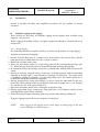
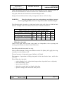
4.2.1. Wing rigging
The following description together with Fig. 4/1 define the procedure of wings rigging.
Sequence of operations in rigging:
1. Put the air brake hand grip in a cockpit in its front position (do not lock this), and the
hand grip of water ballast tank valve in a „closed” position.
2. Retract the air brake in the wing.
3. Shove the main fitting socket (1) of one wing panel on the corresponding fuselage spar
(2). While shoving, keep the planes of wing and fuselage enclosing ribs parallel.
4. In continued motion, the fuselage spar pivot (3) should mate with the ball nest inside the
socket.
5. Moving at wing tip, align the main (1) and rear (6) fitting openings with corresponding
openings in fuselage spar (7) and with these of fuselage rear fitting (8). The torque tubes
of automatic coupling in air brake - (4), and wing ballast valves (5) control system are to
be shifted towards the assembled wing panel.
6. Having juxtaposed the wing with fuselage, as above, insert the main bolt (9) and next
rotate this, which should result in catching the bolt notch at angle bar (13) on fuselage
rib, and the pin (10) at the spring clamp (11).
7. Repeat the operations under items 3 through 6 on opposite wing.
8. Having rigged both wings, connect the wing push rods (12) of flaperon control system
with appropriate push rods in a fuselage.
9. Secure the spring clamps with safety-pins to prevent the main bolt pin sliding off.
Wing de-rigging requires the reverse sequence of operation.
NOTE:
page 4.2
When rigging or de-rigging, do not catch wings at trailing edge as this may
result in damage to control surfaces.
Revision No
Issued:
March 1, 2006
Biuro Projektowe „B”
Bogumił Bereś
FLIGHT MANUAL
SZD-56-2 „Diana-2”
SECTION 4
NORMAL PROCEDURES
Fig. 4/1 Wing rigging
Revision No
Issued:
March 1, 2006
page 4.3
SECTION 4
NORMAL PROCEDURES
Biuro Projektowe „B”
Bogumił Bereś
FLIGHT MANUAL
SZD-56-2 „Diana-2”
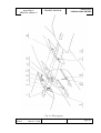
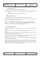
4.2.2. Tailplane rigging
Sequence of operations in tailplane rigging (see Fig. 4/2):
1. Disassemble the fairing (1), removing first the screw (5).
2. Put the horizontal tailplane on the fin, inserting the protruding from stabilizer „T” shape
arm (7) of main fitting into a socket (10).
3. Connect the front (4), and main (7) fittings of horizontal and vertical tailplanes with bolt
(6). Insert the pin (9) in the opening in fin rib and secure this with a safety pin.
4. Connect the elevator control system by coupling the push rod (3) with the top lever (2).
5. Put the fairing (1) on, and secure this with screw (5).
Tailplane de-rigging requires the reverse sequence of operation.
Fig. 4/2 Tailplane rigging
page 4.4
Revision No
Issued:
March 1, 2006
Biuro Projektowe „B”
Bogumił Bereś
FLIGHT MANUAL
SZD-56-2 „Diana-2”
4.3.
SECTION 4
NORMAL PROCEDURES
Daily inspection
Before flying, the glider should be inspected carefully. This concerns also the gliders
stored in hangar since, as learnt by experience, these are exposed to damage during
manoeuvring or when in rest (e.g. rodents).
During the inspection, the followings should be checked:
1.
2.
3.
4.
5.
6.
7.
8.
9.
10.
11.
12.
13.
14.
Glider documents, validity of Inspection Certificate - complete the records.
Condition of the fuselage, wing and tailplane structure and skin (visual inspection).
Reliable securing of the wing and tailplane bolts.
Reliable securing of the flaperon - (through the fuselage top access hole), and elevator
controls.
Condition of canopy, correct closing and opening, and condition of its emergency
jettison system.
Cockpit interior, position of pedals, back rest locking, safety belts, lack of loose items.
Unrestricted deflections and plays in control systems of flaperon, rudder, stabilizer and
air brake.
Correct operation of longitudinal trim system.
Undercarriage condition, wheel rollability, wheel tyre pressure (by eye), cleanness of
the undercarriage well, deflection of shock absorber.
Operation and efficiency of wheel brake.
Condition and operation of tow release.
Water ballast system: symmetric operation (i.e. opening and closing of discharge
valves), correct tanks filling, valves and fillers leak-proof, venting openings clear.
Instruments, pressure ports, battery connection.
Transceiver, make a communication test.
Revision No
Issued:
March 1, 2006
page 4.5
SECTION 4
NORMAL PROCEDURES
4.4.
Biuro Projektowe „B”
Bogumił Bereś
FLIGHT MANUAL
SZD-56-2 „Diana-2”
Pre-flight inspection
Inspection before flight
Prior to flying, check what follows:
1. Locking of assembly bolts connection, and in control systems.
2. Unrestricted deflection of control surfaces over the full range of deflection angles and
control forces.
3. Check if sailplane loading conforms with loading plan given in Section 6 of this Manual.
Check the C.G. position (see TECHNICAL SERVICE MANUAL, Section 4).
4. Correct filling of water ballast tanks.
5. Transportation tail wheel removed.
6. Back rest correctly mounted and secured.
7. Parachute condition.
Procedures before take off
The list of inspection procedures, to be followed immediately before take-off, has been
enclosed at the base of instrument panel.
PRE-FLIGHT CHECKLIST
1.Ballast: - ventilation
- lateral balance.
2.Transport tail wheel removed
3.No loose items in a cockpit
4.Parachute
5.Safety belts
6.Landing gear locking
7.Controls full deflection
8.Air brake
9.Trimming device - for take off
10.Wing flaps - for take off
11.Altimeter setting
12.Cockpit canopy
13.Transceiver
14.Towing rope connection
page 4.6
- CHECK
- CHECK
- CHECK
- CHECK
- PUT ON
- FASTEN
- CHECK
- CHECK
- RETRACT
- SET
- SET
- CHECK
- CLOSE
- CHECK
- CHECK
Revision No
Issued:
March 1, 2006
Biuro Projektowe „B”
Bogumił Bereś
FLIGHT MANUAL
SZD-56-2 „Diana-2”
4.5.
SECTION 4
NORMAL PROCEDURES
Normal procedures and recommended speeds
4.5.1. Aerotowed take off and climb
In aerotowed take off with water ballast:
− recommended tug airplane with possibly high thrust, ensuring high acceleration
over the first phase of ground roll,
− avoid take off from high grass, especially with cross wind,
− take off against the wind, in case of cross wind - take off allowed with cross wind
component not exceeding 5 [m/s] (10 [kt]),
− prior to take off with water ballast, a lateral balance of sailplane should be
checked - with wings level.
− position the sailplane exactly into a wind,
− for take off (ground roll) select a dry, hard and flat terrain,
− set the wing flaps at no more than 21o (in case of lower amount of water ballast
14o or 8o)
− for aerotow employ the towing rope of 30 [m] (98 [ft]) length, at minimum,
− ground roll should be initiated with stick pushed completely fore, until rising the tail
− before lifting the tail, control the ground roll direction with resolute, full
deflections of rudder
− if this does not inadvertently affect the ground roll, raising the tail may be
agitated by delicate braking on main wheel
In case of:
− change to direction in ground roll by more than 15o ÷ 20o or
− touching ground with a wing, right after starting the ground roll,
take the following action without delay:
o release the towing rope
o maintain the control stick pushed forwards onto stop,
o aileron opposite to bank may be used but, due to high lateral inertia of wing
with water ballast, efficiency of this manoeuvre is limited
o use the wheel brake
− after lifting the tail, control the ground roll direction with gentle rudder deflections
− after lifting the tail, if wings are maintained level (no distinct bank), sailplane
response to control deflection is positive and with no delay. Maintaining the
attitude does not require an exceptional piloting skill.
The sailplane maintained in correct attitude behind a tug airplane is directionally
and laterally stable.
− on lifting off, and gaining safe altitude above ground, the wing flap deflection
may be reduced so to reduce the aileron control force, maintaining at the same
time a good tug plane visibility
− setting the climbing flight parameters, it is recommended to continue the flight at
+10° through +12° flap setting,
− over the whole take off run, from ground roll start until gaining safe altitude, it is
not recommended to take any action different from these indispensable to conduct
take-off. Do not retract landing gear, change wing flap position etc.
Revision No
Issued:
March 1, 2006
page 4.7
SECTION 4
NORMAL PROCEDURES
Biuro Projektowe „B”
Bogumił Bereś
FLIGHT MANUAL
SZD-56-2 „Diana-2”
In aerotowed take off without water ballast:
−
−
−
−
−
−
−
−
position the sailplane into a wind, as far as possible,
for take off (ground roll) select a dry, hard and flat terrain,
set the wing flaps at no more than 14o, the optimum range however is 8o through 3o
set the trimming device for take off. To do so press the trim lever on control stick,
set control stick at 30 per cent of full deflection range from its foremost position
and release the trim lever,
set the stick to aileron neutral position, check visually on a wing
keep your left hand close to release hand grip,
ground roll to be initiated with the control stick pushed completely forward, until
raising a tail
before lifting the tail, the ground roll direction is to be corrected with resolute, full
deflections of rudder, in most cases however this is not necessary since soon after
ground roll start the sailplane is lifting the tail and becomes laterally and
directionally more stable
In case of:
− change to direction in ground roll by more than 20o ÷ 30o or
− touching ground with a wing, right after starting the ground roll,
take the following action without delay:
o release the towing rope
o maintain the control stick pushed forwards onto stop,
o apply aileron opposite to bank,
o use the wheel brake
− after lifting the tail, control the ground roll direction with gentle rudder deflections,
− after lifting the tail, if wings are maintained level (no distinct bank), sailplane
response to control deflection is positive and with no delay,
− on lifting off, and gaining safe altitude above ground, the wing flap deflection
may be reduced so to reduce the aileron control force, maintaining at the same
time a good visibility of tug plane,
− at an altitude of approx. 150 [m] ( 330 [ft]), retract the landing gear and correct
the longitudinal trim
Recommended aerotow speed is:
without ballast
with ballast
NOTE:
page 4.8
110 ÷ 120 km/h (59 ÷ 65 [kt])
120 ÷130 km/h (65 ÷ 70 [kt].
In case of touching ground with a wing, and change to the direction by
more than 15o, release the towing rope immediately and push the control
stick forward with simultaneous rudder deflection opposite to possible
rotation.
Revision No
Issued:
March 1, 2006
Biuro Projektowe „B”
Bogumił Bereś
FLIGHT MANUAL
SZD-56-2 „Diana-2”
SECTION 4
NORMAL PROCEDURES
4.5.2. Free flight
Making use of wing flaps:
Adjustment of wing flap setting allows better adoption of the sailplane to actual flight
condition.
Flap settings +8° through -2° are suitable for straight flight and, over the range of
corresponding airspeeds, these are optimum settings. Flap settings +14° through +21°
are aimed for use while circling. The +14° setting is normally used for centering into
thermals as well as for leaving the turbulent lift zones. Settings +14° and +21° are used
when the thermal has been centered, which allows for tight & steady circling in its core.
The +28° setting is used for landing only.
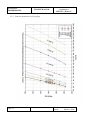
Optimum flap setting at various airspeed range depend strongly on wing surface loading.
In a diagram under item 5.3.3 the optimum wing flap setting is given, versus sailplane
weight and airspeed.
WARNING:
In case of instantaneous or sudden wing flap displacements, the
wing lift changes abruptly, which may result in abrupt alterations of flight
altitude. Thus care must be exercised in this respect while flying close to
the ground surface or near to other sailplanes (gaggle flying).
Low speed flight and stall characteristics:
In flight at a low airspeed down to stall “Diana-2” behaves normally, in a way
representative for most sailplanes. When stalled, the sailplane falls symmetrically, or
with a tendency to drop the wing.
The stall warning is present in the whole range of C.G. positions, the clear stall warning
buffeting occurs at airspeeds higher by approx. 5 [km/h] (3 [kt]) than the values given in
the table, item 5.2.2.
Side slip
This sailplane performs a very flat, inefficient side slip.
Side slip in a landing configuration (air brake and undercarriage extended, flaps at +28o
setting) is inefficient as a manoeuvre aimed to increase sink speed. This may be safely
performed within the airspeed range from the recommended approach speed up to the
VFE =224[km/h] (121[kt]) value. In a steep, dynamic slip a reversal of rudder control
force will appear. The pulling force is low, and does not hinder piloting. In steady flight
conditions, force reversal does not appear. Releasing the controls in a slip results in
sailplane transition to symmetrical flight. Partial-, or full water ballast does not affect the
sailplane slip characteristics. The readings of airspeed indicator in a slip are approx. 5
through 20[km/h] (3 through 11[kt]) below the real values.
Revision No
Issued:
March 1, 2006
page 4.9
SECTION 4
NORMAL PROCEDURES
Biuro Projektowe „B”
Bogumił Bereś
FLIGHT MANUAL
SZD-56-2 „Diana-2”
4.5.3. Approach
Decision on landing, despite sailplane high glide ratio, should be taken early enough. At
an altitude of 100[m] (330[ft]) above the landing site (at the very least), flaps should be
set to +14o through +28o , and landing gear extended. Additionally, for flight path control
in approach the air brake should be used.
Approach should be done at approx. 95 [km/h] (51 [kt]) speed, while in turbulence approx. 10 [km/h] (5 [kt]) above this value.
4.5.4. Landing
Prior to landing, the water ballast should be jettisoned.
NOTE:
Landing with full, or in part jettisoned water ballast allowed only in
necessary instances, and then on airfield only.
WARNING:
Wing flap manoeuvring close to the ground is not recommended
since this may result in dangerous alterations to flight altitude.
In a landing ground roll, pull the elevator control back, to facilitate maintaining the
directional stability, and to avoid the nose touch down when braking on the wheel.
4.5.5. Flight with water ballast
Wing tank water ballast allows to adopt the optimum value of wing surface loading to the
anticipated in flight weather conditions. Tail water ballast allows to obtain the more aft in
flight C.G. position, when flying with water ballast (better performances).
Capacities of water ballast tanks are as follows:
front tank in a wing
2 x 81.4 [litre] (2 x 21.5[gal])
rear tank in a wing
2 x 42.5 [litre] (2 x 11.2[gal])
tail tank
NOTE:
5.6 [litre] (1.48[gal])
This is to remember that, in line with increasing surface loading, both the
minimum speed and the take off run distance are rising as well.
General guidelines on water ballast application
Taking the decision on using water ballast, it is to remember that the maximum allowed
sailplane weight, as well as the range of permissible C.G. position may not be exceeded,
when filling the tanks (in wing and in tail).
page 4.10
Revision No
Issued:
March 1, 2006
Biuro Projektowe „B”
Bogumił Bereś
SECTION 4
NORMAL PROCEDURES
FLIGHT MANUAL
SZD-56-2 „Diana-2”
Tables and formulas allowing to select the correct amount of water ballast are given in
Section 6 of this Manual, as well as in Section 4 of Technical Service Manual.
Only plain, filtered water should be used when filling the tanks.
Flying with water ballast allowed only at temperatures above 0°C (32 °[°F]).
WARNING:
Water freezing may result in a serious damage to sailplane, internal
structure getting flooded, incorrect C.G. position, water valves blocking etc.
The following table, located on a right hand cockpit side wall, allows to find the limit
altitudes for flight with water ballast, in the absence of board thermometer.
MAX. FLIGHT ALTITUDE WITH WATER BALLAST
Min. temperature on ground[oC]
Max. flight altitude
[m]
13.5
1500
17.5
2000
24
3000
31
4000
38
5000
Min. temperature on ground[o F]
Max. flight altitude
[1000 ft]
56.5
5
69.5
8
81
11
90
14
96
17
Filling the wing tanks
Tanks in the right-, and left hand wing panels are independent, valves opening and
closing symmetrically (mechanical interconnection).
Start filling with the front tanks in a wing.
If the predicted amount of wing water ballast exceeds 162.8[litre] (43.0 [gal]), the wing
rear tanks are to be filled as well.
The total capacity of wing tanks ranges 248[litre] (65.5[gal]).
The sequence of operations in filling wing tanks is the same for the front-, and for the
rear ones.
When filling the wing tanks:
−
−
−
−
−
set the sailplane level - with no bank (support the wing with a brace or by hand),
close the discharge valves,
insert a funnel into filler,
choke the rear tank inlet in a funnel with a plug,
open the venting orifice located in safety valves
Revision No
Issued:
March 1, 2006
page 4.11
SECTION 4
NORMAL PROCEDURES
Biuro Projektowe „B”
Bogumił Bereś
FLIGHT MANUAL
SZD-56-2 „Diana-2”
− pour the water in measured amount or brim-full, until obtaining the continuous
outflow from the filler,
− repeat this procedure for filling the wing rear tanks.
WARNING: Never fill the tanks with water supply hose inserted directly into tank
filler.
− having filled the tanks, remove funnels and close valves,
Filling the tail ballast tank
Tail tank is installed at the base of the fin, filler on the right hand fin surface.
The discharge valve of tail ballast tank is opened every time the valves of wing front
tanks are being opened (controls interconnection).
NOTE:
Tail ballast tank should be filled, as a rule, after filling the wing tanks.
Pour water in the measured amount through the funnel inserted into the filler. An
eventual excess of water flows out through the venting opening.
Jettison of ballast water
Discharge of ballast water is controlled by means of lever located on the cockpit right
hand side.
Rotating the short lever backwards results in opening of discharge valves of wing rear
tanks.
Rotating the long lever backwards results in opening the discharge valves of wing front
and rear tanks together with the tail tank valve.
Water outflow can be stopped (i.e. the discharge valves of wing and tail tanks closed) by
rotating the appropriate lever of water discharge control forwards.
It is not possible to discharge the water from wing front tanks without discharging first
the water from wing rear tanks.
Water from wing tanks flows partially on the wing bottom surfaces and fuselage. Water
outflow remains imperceptible from the cockpit. Time of water complete jettison
depends on the amount of water. With wing tanks full, it takes approx. 3 minutes (jettison
of water from tail tank is accomplished in shorter time).
page 4.12
Revision No
Issued:
March 1, 2006
Biuro Projektowe „B”
Bogumił Bereś
FLIGHT MANUAL
SZD-56-2 „Diana-2”
SECTION 4
NORMAL PROCEDURES
4.5.6. High altitude flight
One should keep in mind that, in line with increasing flight altitude the true airspeed is
higher than this indicated one.
Therefore the maximum allowed airspeed VNE must be reduced according to the table,
item 2.2, of this Manual.
4.5.7. Flight in rain
When flying in rain, a degradation to sailplane performances should be taken into
account. In circling, and in approach increase airspeed by approx. 10 [km/h](5.4 [kt]).
In poor visibility or with foggy canopy glassing, open the side window and cockpit
ventilation valve.
It is recommended to remove the rain drops and dry the sailplane prior to take-off.
Do not enter the icing condition zones with a wet glider.
Revision No
Issued:
March 1, 2006
page 4.13
SECTION 4
NORMAL PROCEDURES
FLIGHT MANUAL
Biuro Projektowe „B”
Bogumił Bereś
SZD-56-2 „Diana-2”
Intentionally left blank
page 4.14
Revision No
Issued:
March 1, 2006
Biuro Projektowe „B”
Bogumił Bereś
FLIGHT MANUAL
SZD-56-2 „Diana-2”
SECTION 5
PERFORMANCES
SECTION 5
5.
PERFORMANCES
5.1. Introduction
5.2
5.2. Approved data
5.2
5.2.1. Airspeed indicator system calibration
5.2
5.2.2. Stall speeds
5.3
5.3. Additional, non approved information
5.3
5.3.1. Demonstrated cross wind performance
5.3
5.3.2. Flight polar (calculated)
5.4
5.3.3. Data on optimum use of wing flap
5.6
Revision No
Issued:
March 1, 2006
page 5.1
SECTION 5
PERFORMANCES
FLIGHT MANUAL
Biuro Projektowe „B”
Bogumił Bereś
SZD-56-2 „Diana-2”
5.1. Introduction
Section 5 provides approved data for airspeed indicator system calibration and stall
speeds. This contains also non-approved further values and data.
The data in a charts have been computed from flight tests with the sailplane in good
condition and using average piloting techniques.
5.2.
Approved data
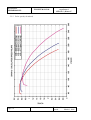
5.2.1. Airspeed indicator system calibration
IAS (kt)
30
40
50
60
70
80
90 100 110 120 130 140 150
280
150
260
140
240
130
220
120
110
CAS (km/h)
200
90
160
80
CAS (kt)
100
180
140
70
120
60
100
50
80
40
60
60
80
100 120 140 160 180 200 220 240 260 280
30
IAS (km/h)
Fig. 5/1 IAS Calibration
NOTE:
The above diagram presents CAS versus IAS.
CAS - Calibrated Airspeed - instrument value (airspeed indicator reading),
corrected for instrument error and aerodynamic calibration error.
IAS - Indicated Airspeed - instrument reading corrected for instrument
error only. IAS values presented in this Manual are given assuming zero
instrument error.
page 5.2
Revision No
Issued:
March 1, 2006
Biuro Projektowe „B”
Bogumił Bereś
SECTION 5
PERFORMANCES
FLIGHT MANUAL
SZD-56-2 „Diana-2”
5.2.2. Stall speeds
In the following table the IAS stall speeds values (airspeed indicator readings) are given
for particular wing flap settings, both in straight flight and in circling:
in flight mass
wing
flap
setting
283[kg] (624[lb])
straight flight
500[kg] (1102[lb])
circling φ=45°
straight flight
circling φ=45°
[km/h]
[kt]
[km/h]
[kt]
[km/h]
[kt]
[km/h]
[kt]
-2°
82
44
90
49
101
55
109
59
+3°
78
42
86
46
94
51
105
57
+28°
70
38
82
44
84
45
100
54
Landing gear extending does not affect the stall speeds value.
Altitude loss during recovery from stall depends on the actual glider loading, and is
contained within the range:
up to 90[m] (300[ft]) approx.
5.3.
Additional, non approved information
5.3.1. Demonstrated cross wind performance
The correct sailplane behaviours in take off and landing have been demonstrated at cross
wind component of:
in aerotowed take off ............................ 17[km/h] (9[kt]),
in landing.............................................. 17[km/h] (9[kt]).
Revision No
Issued:
March 1, 2006
page 5.3
SECTION 5
PERFORMANCES
FLIGHT MANUAL
Biuro Projektowe „B”
Bogumił Bereś
SZD-56-2 „Diana-2”
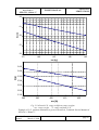
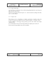
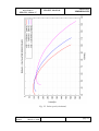
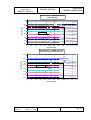
5.3.2. Polar speed (calculated)
page 5.4
Revision No
Issued:
March 1, 2006
Biuro Projektowe „B”
Bogumił Bereś
FLIGHT MANUAL
SZD-56-2 „Diana-2”
SECTION 5
PERFORMANCES
Fig. 5/2 Polar speed (calculated)
Revision No
Issued:
March 1, 2006
page 5.5
SECTION 5
PERFORMANCES
FLIGHT MANUAL
Biuro Projektowe „B”
Bogumił Bereś
SZD-56-2 „Diana-2”
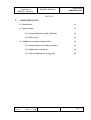
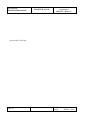
5.3.3. Data on optimum use of wing flap
page 5.6
Revision No
Issued:
March 1, 2006
Biuro Projektowe „B”
Bogumił Bereś
FLIGHT MANUAL
SZD-56-2 „Diana-2”
SECTION 5
PERFORMANCES
Fig. 5/3 Data on optimum use of wing flap
Revision No
Issued:
March 1, 2006
page 5.7
SECTION 5
PERFORMANCES
FLIGHT MANUAL
Biuro Projektowe „B”
Bogumił Bereś
SZD-56-2 „Diana-2”
Intentionally left blank
page 5.8
Revision No
Issued:
March 1, 2006
Biuro Projektowe „B”
Bogumił Bereś
FLIGHT MANUAL
SZD-56-2 „Diana-2”
SECTION 6
WEIGHT AND BALANCE
SECTION 6
6.
WEIGHT AND BALANCE
6.1. Introduction
6.2
6.2. Weight and balance record / permitted payload-range
6.2
6.3. Tail ballast limitations
6.4
Revision No
Issued:
March 1, 2006
page 6.1
SECTION 6
WEIGHT AND BALANCE
6.1.
Biuro Projektowe „B”
Bogumił Bereś
FLIGHT MANUAL
SZD-56-2 „Diana-2”
Introduction
This Section contains the payload range within which the sailplane may be safely
operated.
Procedures for weighing the sailplane and the calculation method for establishing the
permitted payload range, as well as the list of equipment available for this sailplane, and
equipment installed in the weighed sailplane are contained in the Technical Service
Manual, Sections 4 and 6.
6.2.
Weight and balance record / permitted payload-range
The entries in the following tables are valid only for the sailplane the Fact. No of which
is shown on the head page of this Flight Manual.
The loading plan is to be calculated basing on the last weighing.
Valid for Serial No:
Permitted weight of
pilot & parachute
Date
Empty
weight
C.G.
position
with water
ballast
Max.
page 6.2
Min.
without water
ballast
Max.
Approved
Date Signed
Min.
Revision No
Issued:
March 1, 2006
Biuro Projektowe „B”
Bogumił Bereś
SECTION 6
WEIGHT AND BALANCE
FLIGHT MANUAL
SZD-56-2 „Diana-2”
For calculation of the permitted max. and min. pilot weight refer to Technical Service
Manual, Section 4.
To verify the correctness of sailplane loading condition refer to Technical Service
Manual, Section 4.
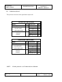
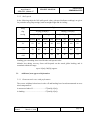
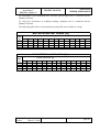
The following table allows to determine the permissible water ballast in a wing.
MAX. WATER BALLAST IN WING [kg]
empty
weight
[kg]
175
180
185
190
cockpit useful load [kg]
55
248
248
248
248
60
248
248
248
248
65
248
248
248
245
70
248
248
245
240
75
248
245
240
235
80
245
240
235
230
85
240
235
230
225
90
235
230
225
220
95
230
225
220
215
100
225
220
215
210
105
220
215
210
205
110
215
210
205
200
115
210
205
200
195
MAX. WATER BALLAST IN WING [lb]
empty
weight
[lb]
390
400
410
419
cockpit useful load [lb]
121
547
547
547
547
130
547
547
547
547
140
547
547
547
543
150
547
547
542
533
Revision No
Issued:
March 1, 2006
160
547
542
532
523
170
542
532
522
513
180
532
522
512
503
190
522
512
502
493
200
512
502
492
483
210
502
492
482
473
220
492
482
472
463
230
482
472
462
453
242
470
460
450
441
253
459
449
439
430
page 6.3
SECTION 6
WEIGHT AND BALANCE
6.3.
FLIGHT MANUAL
Biuro Projektowe „B”
Bogumił Bereś
SZD-56-2 „Diana-2”
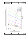
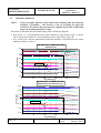
Tail ballast limitations
NOTE:
Using the higher amount of tail ballast than resulting from the following
diagrams is forbidden – this involves a risk of exceeding the approved
rearmost CG position, thus operating the sailplane beyond the verified and
approved operating limitations range.
Procedure to determine the tail ballast basing on the following diagram:
• from point „A”, corresponding to the actual amount of wing ballast, draw a vertical
line to intersection with curve corresponding to the cockpit load - point „B”
• on a vertical axis, find the maximum permissible amount of tail ballast for the actual
loading condition - point „C”
TAIL BALLAST = f (WING BALLAST)
with back-rest
6.0
tail ballast [kg]
95
90
85
5.0
"C"
"B"
80
4.0
75
3.0
pilot weight [kg]
70
2.0
65
60
1.0
0.0
0
50
100
150
wing ballast [kg]
"A"
200
250
TAIL BALLAST = f (WING BALLAST)
without back-rest/ head-rest only
6.00
100
105
95
5.00
tail ballast [kg]
90
4.00
85
"B"
"C"
80
3.00
pilot weight [kg]
75
2.00
70
1.00
65
0.00
0
page 6.4
50
100
150
wing ballast [kg]
"A"
200
250
Revision No
Issued:
March 1, 2006
Biuro Projektowe „B”
Bogumił Bereś
SECTION 6
WEIGHT AND BALANCE
FLIGHT MANUAL
SZD-56-2 „Diana-2”
TAIL BALLAST = f (WING BALLAST)
with back-rest
14.0
tail ballast [lb]
210
12.0
"C"
10.0
190
200
"B"
180
170
8.0
pilot weight [lb]
6.0
160
150
4.0
140
2.0
130
0.0
0
50
100
150
200
250
300
350
wing ballast [lb]
"A"
400
450
500
550
500
550
TAIL BALLAST = f (WING BALLAST)
without back-rest/ head-rest only
14.00
220
tail ballast [lb]
12.00
200
10.00
"C"
8.00
210
"B"
190
pilot weight [lb]
180
6.00
170
4.00
160
150
2.00
140
0.00
0
50
100
Revision No
Issued:
March 1, 2006
150
200
250
300
350
wing ballast [lb]
400"A" 450
page 6.5
SECTION 6
WEIGHT AND BALANCE
FLIGHT MANUAL
Biuro Projektowe „B”
Bogumił Bereś
SZD-56-2 „Diana-2”
Intentionally left blank
page 6.6
Revision No
Issued:
March 1, 2006
Biuro Projektowe „B”
Bogumił Bereś
FLIGHT MANUAL
SZD-56-2 „Diana-2”
SECTION 7
SAILPLANE DESCRIPTION
SECTION 7
7.
SAILPLANE AND SYSTEMS DESCRIPTION
7.1. Introduction
7.2
7.2. Cockpit controls
7.2
7.2.1. Aileron & elevator control
7.2
7.2.2. Rudder
7.2
7.2.3. Wing flaps
7.2
7.2.4. Longitudinal trim
7.2
7.2.5. Tow release
7.2
7.3. Instrument panel
7.3
7.4. Landing gear
7.5
7.5. Cockpit, canopy, seat and safety belts
7.5
7.6. Board instrument system
7.5
7.7. Air brake
7.6
7.8. Baggage compartment
7.6
7.9. Water ballast system
7.6
7.10. Miscellaneous equipment
7.6
7.10.1. Transceiver
7.6
7.10.2. Ventilation
7.6
Revision No
Issued:
March 1, 2006
page 7.1
SECTION 7
SAILPLANE DESCRIPTION
7.1.
Biuro Projektowe „B”
Bogumił Bereś
FLIGHT MANUAL
SZD-56-2 „Diana-2”
Introduction
This Section contains description of sailplane and its systems, and provides information
on operation of these.
Refer to Section 9 for details of optional systems and equipment.
7.2.
Cockpit controls
7.2.1. Aileron & elevator control
Ailerons and elevator are controlled with control stick located on right hand cockpit side.
The transceiver „push to talk” button is installed on the control stick.
7.2.2. Rudder
Rudder pedals are in-flight adjustable (9 settings). Grip of pedal adjustment is located in
the lower part of instrument panel column.
7.2.3. Wing flaps
Wing flaps are operated by means of a handle located on a cockpit left hand side. Flaps
control handle can be locked at 7 various settings. To facilitate access to -, and egress
from a cockpit, the flap control handle is folded up.
7.2.4. Longitudinal trim
Trim device is controlled by means of a lever on control stick. Pressure on a lever
disconnects the elevator control from trimming spring. On releasing the lever, the spring
supports retaining the control stick in selected position. Indicator of trimming device
position is located on the right hand cockpit side. With the lever on control stick held
pressed, the trimming device may be precisely set with an indicator.
7.2.5. Tow release
The (yellow) grip is installed on a column of instrument panel, on the left hand side. The
hook is released on pulling at the grip.
To connect the rope, pull on the yellow grip, insert a rope link and release the grip. Next
check the correct connection of rope.
page 7.2
Revision No
Issued:
March 1, 2006
Biuro Projektowe „B”
Bogumił Bereś
FLIGHT MANUAL
SZD-56-2 „Diana-2”
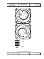
7.3.
SECTION 7
SAILPLANE DESCRIPTION
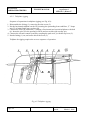
Instrument panel
The instrument panel (1) with standard equipment comprises the following set of board
instruments (see drawing):
−
−
−
−
−
altimeter 60 mm diameter
(2)
airspeed indicator 60 mm dia
(3)
variometer ±10 [m/s] (±2000 [ft/mint]) (4)
compass KI-13A
(10)
compensator of total energy variometer KWEC-2 (8)
11
12
1
10
13
8
9
6
7
4
3
2
5
Fig. 7/1 Scheme of board instrument system
Revision No
Issued:
March 1, 2006
page 7.3
SECTION 7
SAILPLANE DESCRIPTION
FLIGHT MANUAL
Biuro Projektowe „B”
Bogumił Bereś
SZD-56-2 „Diana-2”
1
12
2
13
3
14
4
15
5
16
6
17
7
18
8
19
9
20
10
21
11
22
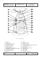
Fig. 7/2 Cockpit view
1.
2.
3.
4.
5.
6.
7.
8.
9.
10.
11.
Canopy
Canopy hinge
Wing flap control handle
Wheel brake handle
Air brake control lever
Tow release grip
Landing gear locking lever
Landing gear extension/retraction slider
Pedal adjustment grip
Head rest adjustment
Head-rest
page 7.4
12.
13.
14.
15.
16.
17.
18.
19.
20.
21.
22.
Pedals
Balancing weight
Instrument panel
Cockpit canopy emergency jettison grip
Longitudinal trim lever
Control stick
Water ballast jettison levers
Trim indicator
Safety belts
Seat cushion
Back-rest, or head-rest
Revision No
Issued:
March 1, 2006
Biuro Projektowe „B”
Bogumił Bereś
FLIGHT MANUAL
SZD-56-2 „Diana-2”
7.4.
SECTION 7
SAILPLANE DESCRIPTION
Landing gear
The retraction mechanism of landing gear is controlled with a slider on a left hand
cockpit side. With slider in a front position the landing gear is retracted and, in a rear
position - extended. A locking lever is provided on a slider grip. The landing gear is
extended by shifting the slider grip (8) inboard and backward, not touching the lever (7).
The extended landing gear is correctly locked, when after pushing the slider home to its
extreme position a characteristic knock can be heard, and slider can not be moved.
Unlocking of landing gear mechanism is achieved by pressing the lever. When retracting,
it is recommended to pull first the slider grip slightly back, unlock the mechanism at this
position and next - to push the slider forwards not touching the lever (7). On pushing the
slider home, forwards, lock the landing gear by re-setting the slider grip to the left,
towards the cockpit side board (outboard).
The doors of landing gear house are closed automatically, with aid of loading spring.
NOTE:
Pressing the locking lever, while on ground, may result in landing gear
retraction and damage to the doors of landing gear house.
The brake of main wheel is activated with a lever located on the air brake slider. This
lever is used also to lock the air brake in its retracted position.
7.5.
Cockpit, canopy, seat and safety belts.
Canopy opening (fore, upwards) is enabled after shifting the lock levers (white) up. The
canopy is retained in opened position by means of a gas spring. The cockpit provides
space for pilots up to 185[cm] (6[ft]) in height, with a back parachute. The thickness of
parachute, or back cushion may not be less than 12[cm] (4.7[in]). Cockpit adjustment to
the pilot’s height can be obtained on the way of pedals adjustment (paragraph 7.2.2) and
adequate adjustment of back rest (on ground only). The mounting bolts of back rest must
be arranged symmetrically and correctly mate with the openings. The adjustable head rest
is provided on a back rest.
The four-point safety belts are included in sailplane standard equipment.
7.6.
Board instrument system
The board instrument system contains (see drawing item 7.3):
−
−
−
−
−
−
−
instrument panel (1)
compensating bottles (9)
two static pressure ports in fuselage front part (11)
total pressure port in fuselage nose (12)
additional pressure port nest for special instruments (13)
hose joint (7) enabling disconnection of the instrument panel from sailplane
drainage units of the total-, and static pressure ducts, accessible in front of the
instrument panel (6)
The instrument panel is mounted to a column with a screw (5).
Revision No
Issued:
March 1, 2006
page 7.5
SECTION 7
SAILPLANE DESCRIPTION
7.7.
FLIGHT MANUAL
Biuro Projektowe „B”
Bogumił Bereś
SZD-56-2 „Diana-2”
Air brake
Air brake control is actuated conventionally, with a slider located on the cockpit left hand
side.
On the slider a lever is provided - used to lock the air brake in its retracted position and,
also to brake the landing gear wheel.
7.8.
Baggage compartment
A baggage compartment is located above the fuselage spar, accessible from the cockpit.
Baggage is fastened with straps to the lugs provided in baggage compartment. Maximum
weight of luggage in baggage compartment 5 [kg] (11 [lb]).
Carriage of dangerous or flammable materials in baggage compartment forbidden.
7.9.
Water ballast system
Jettison of water ballast is controlled with levers located on the cockpit right hand side
(see item 4.5.5).
7.10. Miscellaneous equipment
7.10.1. Transceiver
Sailplane is adapted for transceiver installation.
As a standard, the tubular antenna is installed in the fin nose, with a cable led to the
instrument panel.
7.10.2. Ventilation
The cockpit is ventilated by means of a side window with deflectable ventilation tab.
Moreover, an adjustable air blow on the canopy portion above the instrument panel is
provided - controlled with a (black) slider on the left hand side, and the adjustable nozzle
on the right hand side, in front of the control stick. Pressing the nozzle home stops air
blow.
page 7.6
Revision No
Issued:
March 1, 2006
Biuro Projektowe „B”
Bogumił Bereś
FLIGHT MANUAL
SZD-56-2 „Diana-2”
SECTION 8
SAILPLANE MAINTENANCE
SECTION 8
8.
SAILPLANE HANDLING, CARE AND MAINTENANCE
8.1. Introduction
8.2
8.2. Sailplane periodic inspections
8.2
8.3. Sailplane alterations or repairs
8.2
8.4. Ground handling / road transport
8.2
8.4.1. Ground handling
8.2
8.4.2. Road transport
8.3
8.5. Cleaning and care
Revision No
Issued:
March 1, 2006
8.3
page 8.1
SECTION 8
SAILPLANE MAINTENANCE
8.1.
FLIGHT MANUAL
Biuro Projektowe „B”
Bogumił Bereś
SZD-56-2 „Diana-2”
Introduction
This Section contains manufacturer’s recommended procedures for proper ground
handling and servicing of the sailplane. In this connection, certain inspection and
maintenance requirements are identified which must be followed if the sailplane is to
retain the new plane performance and dependability.
It is wise to follow a planned schedule of lubrication and maintenance based on the
specific climatic and operating conditions encountered.
8.2.
Sailplane periodic inspections
The sailplane inspection should be performed at the beginning of every flying season.
The scope and time periods of all inspections are contained in the Technical Service
Manual for SZD-56-2 "Diana-2" sailplane.
8.3.
Sailplane alterations or repairs
Repairs and alterations are referred to in the Repair Manual for SZD-56-2 "Diana-2"
sailplane.
It is essential that the responsible airworthiness Authority be notified prior to any
alterations on the sailplane, to ensure that the airworthiness of the sailplane is not
compromised.
8.4.
Ground handling / road transport
8.4.1. Ground handling
With respect to ground handling: i.e. securing against wind, towing rope connection,
anchoring, proceeding with a wet glider, draining of the instrument pneumatic system the generally known rules for performance gliders should be observed. Sailplane is to be
anchored using towing hook, clamps for wing transport wheels as well as with wide strap
at the fuselage-fin transition.
NOTE:
Leaving the glider outside, without protection against environmental
conditions and sunlight, will harmfully affect durability of the lacquer coat
In case of prolonged pause in operation, sailplane de-rigging is recommended.
If the sailplane is to be stored in rigged condition, the wings should be supported at tips.
The metal fittings and elements should be greased.
page 8.2
Revision No
Issued:
March 1, 2006
Biuro Projektowe „B”
Bogumił Bereś
FLIGHT MANUAL
SZD-56-2 „Diana-2”
SECTION 8
SAILPLANE MAINTENANCE
Put the individual covers on the sailplane main sets.
NOTE:
Do not hangar in wet covers. The hangared sailplane should not be
exposed to environmental conditions or humidity.
Put the fuselage on the belly supports, placed in front of the undercarriage house and
under the fin. Set the wings chord vertical, and shore the wings with band supports at the
leading edge.
Release pressure in the tyre.
For sailplane ground rolling the "tail forwards" attitude is recommended.
Pulling the sailplane at wing tips not recommended.
For motor-car transportation in "nose forwards" attitude the tow release should be used
and a towing rope with connection link.
Immobilize the control stick (with safety belts).
8.4.2. Road transport
Standard procedure for transport of de-rigged sailplane on a trailer involves the special
composite sleeves shoved on the fuselage spar, on which the wing clamps are installed.
The outboard sleeve portions, inserted in the cut-out in side boards of sailplane standard
trailer, are used to immobilise the transported sailplane.
In case of glider transport in a trailer, without composite special clamps, the assemblies
may be fastened at their external surfaces with the wide clamps upholstered with a soft
padding, or with bands supports.
Fasten the wings at the fittings close to the root ribs and support under the leading edge
at semispan, wing chord vertical.
The fuselage should be fastened at the undercarriage wheels and at the fuselage spar.
The tailplane to be fixed in clamps.
For transportation, protect the mating surfaces of the fittings, access openings and
bearings against dust and dirt.
Immobilize the control surfaces. Protect the canopy with a flannel cover.
In case the open trailer is used, the external surfaces of sailplane main components
should be protected with individual covers and, in case of rain, with a plastic foil.
8.5.
Cleaning and care
Moisture and direct sunlight have a harmful effect on composite material and lacquer
coat therefore, for modern sailplanes, the proper maintenance and care are necessary.
Revision No
Issued:
March 1, 2006
page 8.3
SECTION 8
SAILPLANE MAINTENANCE
FLIGHT MANUAL
Biuro Projektowe „B”
Bogumił Bereś
SZD-56-2 „Diana-2”
In particular, high moisture combined with high temperature should be avoided (e.g.
poorly ventilated trailer with accumulated moisture, exposed to sun rays). If the moisture
penetrates into the hardly accessible structure areas, the glider should be de-rigged and its
wet components stored in a dry room to get dried.
In case of soiling the external surfaces (e.g. with insects) it is recommended to wash
these with a clear water with a gentle detergent, without an abrasive agent. Wipe the
washed area with a flannel rag (or shammy). Dry the wet sailplane interior (air brake
boxes), make sure the drainage openings are free.
The lifting surfaces should be polished time to time with a polishing paste, chord-wise
direction movement, mechanically or manually with a special slat.
NOTE:
For lifting surfaces polishing only the non-siliceous agents are allowed.
The remnants of adhesive tape should be cleaned with extraction gasoline.
Canopy perspex should be cleaned with a special care agent or with a large amount of
clear water. In no case the dry rag or similar can be used for removal of dust and dirt.
Protect the canopy glassing against dust or sun with a flannel cover.
The safety belts should be regularly inspected against tear, or wear evidence, corroded
fittings etc. Check from time to time the correct functioning of belts fastener.
page 8.4
Revision No
Issued:
March 1, 2006
Biuro Projektowe „B”
Bogumił Bereś
SECTION 9
SUPPLEMENTS
FLIGHT MANUAL
SZD-56-2 „Diana-2”
SECTION 9
9.
SUPPLEMENTS
9.1. Introduction
9.2
9.2. List of inserted supplements
9.2
9.3. Supplements inserted
9.2
Revision No
Issued:
March 1, 2006
page 9.1
SECTION 9
SUPPLEMENTS
9.1.
FLIGHT MANUAL
Biuro Projektowe „B”
Bogumił Bereś
SZD-56-2 „Diana-2”
Introduction
This Section contains the supplements necessary to safely and efficiently operate the
sailplane when equipped with various optional systems and equipment not provided with
the standard sailplane.
9.2.
List of inserted supplements
Date of
insertion
9.3.
page 9.2
Doc. No
Title of the inserted supplement
Supplements inserted
Revision No
Issued:
March 1, 2006