1
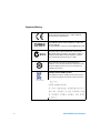
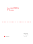
Agilent N4985A
System Amplifiers
Operating and Service
Manual
Agilent Technologies
Notices
© Agilent Technologies, Inc. 2013
Warranty
No part of this manual may be reproduced in
any form or by any means (including electronic storage and retrieval or translation
into a foreign language) without prior agreement and written consent from Agilent
Technologies, Inc. as governed by United
States and international copyright laws.
The material contained in this document is provided “as is,” and is subject to being changed, without notice,
in future editions. Further, to the maximum extent permitted by applicable
law, Agilent disclaims all warranties,
either express or implied, with regard
to this manual and any information
contained herein, including but not
limited to the implied warranties of
merchantability and fitness for a particular purpose. Agilent shall not be
liable for errors or for incidental or
consequential damages in connection with the furnishing, use, or performance of this document or of any
information contained herein. Should
Agilent and the user have a separate
written agreement with warranty
terms covering the material in this
document that conflict with these
terms, the warranty terms in the separate agreement shall control.
Manual Part Number
N4985-90001
Edition
First Edition, June 2013
Printed in Malaysia
Agilent Technologies, Inc.
Phase 3 Bayan Lepas Free Industrial Zone
Bayan Lepas, Penang 11900 Malaysia
Certification
Agilent Technologies certified that this
product met its published specifications at
the time of shipment from the factory. Agilent Technologies further certifies that its
calibration measurements are referenced to
the United States National Institute of Standards and Technology (NIST, formerly NBS),
to the extent allowed by the Institute’s calibration facility, and to the calibration facilities of other International Standards
Organization members.
Technology Licenses
The hardware and/or software described in
this document are furnished under a license
and may be used or copied only in accordance with the terms of such license.
Restricted Rights Legend
U.S. Government Restricted Rights. Software and technical data rights granted to
the federal government include only those
rights customarily provided to end user customers. Agilent provides this customary
commercial license in Software and technical data pursuant to FAR 12.211 (Technical
Data) and 12.212 (Computer Software) and,
for the Department of Defense, DFARS
252.227-7015 (Technical Data - Commercial
Items) and DFARS 227.7202-3 (Rights in
Commercial Computer Software or Computer Software Documentation).
Safety Notices
CAUTION
A CAUTION notice denotes a hazard. It calls attention to an operating procedure, practice, or the like
that, if not correctly performed or
adhered to, could result in damage
to the product or loss of important
data. Do not proceed beyond a
CAUTION notice until the indicated
conditions are fully understood and
met.
WA R N I N G
A WARNING notice denotes a
hazard. It calls attention to an
operating procedure, practice, or
the like that, if not correctly performed or adhered to, could result
in personal injury or death. Do not
proceed beyond a WARNING
notice until the indicated conditions are fully understood and
met.
Agilent N4985A System Amplifiers
Compliance Notices and Regulatory Information
Compliance with Electromagnetic Compatibility (EMC)
This product conforms with the protection requirements of
EMC Directive 2004/108/EC for Electromagnetic
Compatibility.
This product complies to the EMC Directive by assessment
according to the IEC/EN61326- 1:2005 EMC standard.
In order to preserve the EMC performance of this product,
any cable which becomes worn or damaged must be replaced
with the same type and specifications.
WEEE Compliance
This product complies with the WEEE Directive
(2002/96/EC) marking requirements. The affixed label
indicates that you must not discard this electrical/electronic
product in domestic household waste.
Product Category: With reference to the equipment types in
the WEEE Directive Annex I, this product is classed as a
"Monitoring and Control Instrumentation" product.
Do not dispose in domestic household waste.
To return unwanted products, contact your local Agilent
office, or see www.agilent.com for more information.
Agilent N4985A System Amplifiers
3
Regulatory Markings
The CE mark shows that the product complies with all the
relevant European Legal Directives.
ICES/NMB-001 indicates that this ISM device complies with
Canadian ICES-001.
Cet appareill ISM est conforme a la norme NMB-001 du Canada.
The C-Tick mark is a registered trademark of the Spectrum
Management Agency of Australia. This signifies compliance
with the Australian EMC Framework Regulations under the
terms of the Radio Communications Act of 1992.
This symbol indicates the time period during which no
hazardous or toxic substance elements are expected to leak or
deteriorate during normal use. Forty years is the expected
useful life of the product.
South Korean Class A EMC declaration:
This equipment is Class A suitable for professional use and is
for use in electromagnetic environments outside of the home.
4
Agilent N4985A System Amplifiers
Contacting Agilent
For more information, please contact your nearest Agilent
office.
Americas
Canada
Latin America
United States
(877) 894-4414
305 269 7500
(800) 829-4444
Asia Pacific
Australia
China
Hong Kong
India
Japan
Korea
Malaysia
Singapore
Taiwan
Thailand
1 800 629 485
800 810 0189
800 938 693
1 800 112 929
81 426 56 7832
080 769 0800
1 800 888 848
1 800 375 8100
0800 047 866
1 800 226 008
Europe
Austria
Belgium
Denmark
Finland
France
Germany
Ireland
Italy
Netherlands
Spain
Sweden
Switzerland (French)
Switzerland (German)
United Kingdom
Other European Countries:
0820 87 44 11
32 (0) 2 404 93 40
45 70 13 15 15
358 (0) 10 855 2100
0825 010 700
01805 24 6333
1890 924 204
39 02 92 60 8484
31 (0) 20 547 2111
34 (91) 631 3300
0200-88 22 55
41 (21) 8113811 (Opt 2)
0800 80 53 53 (Opt 1)
44 (0) 118 9276201
www.agilent.com/find/contactus
Or, go to www.agilent.com/find/assist for more information.
Agilent N4985A System Amplifiers
5
Declaration of Conformity
A copy of the Manufacturer’s European Declaration of
Conformity for these System Amplifiers can be obtained by
contacting your local Agilent Technologies sales
representative, or copies can be downloaded from the
Agilent Technologies, Inc. Web site at:
http://regulations.corporate.agilent.com/DoC/search.htm
6
Agilent N4985A System Amplifiers
Contents
1
Introduction 9
Product Overview 10
Features of the Agilent N4985A Amplifiers 12
Applications 13
2
Installation 15
Initial Inspection 16
Service and Recalibration 17
Related Documentation 17
Operating and Safety Precautions 18
ESD Damage 18
Connector Care 19
3
Specifications 21
General Specifications 22
Specifications 22
Supplementary Specifications 37
Physical Specifications 37
Mechanical Dimensions 38
4
Operation Guide 39
Operating Instructions 40
Performance Verification 40
Example Application 41
Service and Maintenance 42
Service 42
Maintenance 42
Agilent N4985A System Amplifiers
7
This page is intentionally left blank.
8
Agilent N4985A System Amplifiers
Agilent N4985A System Amplifiers
Operating and Service Manual
1
Introduction
Product Overview 10
“Features of the Agilent N4985A Amplifiers" on page 12
“Applications" on page 13
This chapter provides an overview of the N4985A Amplifiers.
Agilent Technologies
9
Product Overview
High Performance Broadband RF Amplifier
The N4985A- S30 and N4985A- S50 system amplifiers are high
performance, broadband amplifiers featuring baseband RF
(<100 kHz) through millimeter wave frequency coverage.
These amplifiers, which have many uses in research,
development, or production- line environment, are a useful
addition to the laboratory where RF, microwave, or
millimeter wave measurements are made. Typical
applications include:
• RF Source Amplifier.
• Mixer LO Amplifier.
• Noise Figure LNA and Noise Figure System Amplifier.
• Pulse Amplifier and time domain applications.
• Digital communication systems.
• Antenna research and development.
• General purpose RF gain block.
N4985A-S30 Amplifier
N4985A-S50 Amplifier
Figure 1-1 Agilent N4985A-S30/S50 amplifier
10
Agilent N4985A System Amplifiers
High Performance System Amplifier
The N4985A- P15 and N4985A- P25 are high performance,
broadband amplifiers with excellent power and gain up to
50 GHz, which have many uses in research, development, or
production- line environment. These amplifiers are a useful
addition to the laboratory where RF, microwave, or
millimeter wave measurements are made. Typical
applications include:
• Driver for high power amplifiers such as TWT or linear
power amplifiers.
• Overcome system losses such as long transmission lines,
power dividers, etc.
• Antenna research and development; antenna
characterization systems.
• Broadband RF characterization.
N4985A-P15 Amplifier
N4985A-P25 Amplifier
Figure 1-2 Agilent N4985A-P15/P25 amplifier
Agilent N4985A System Amplifiers
11
Features of the Agilent N4985A Amplifiers
The N4985A is a high performance amplifier featuring
broadband frequency coverage.
Model
Frequency Range
Gain
N4985A-S30
100 kHz to 30 GHz
30 dB
N4985A-S50
100 kHz to 50 GHz
30 dB
N4985A-P15
10 MHz to 50 GHz
25 dB
N4985A-P25
2 GHz to 50 GHz
27 dB
N4985A-S30 and N4985A-S50
• The amplifier is designed to be a multi- use laboratory RF
amplifier as a gain block for frequency domain
applications or as a time domain pulse amplifier.
• The amplifier’s small size and versatile performance make
it an excellent selection as a general purpose gain block
with moderate power output in a single package
potentially replacing two or three narrower band
amplifiers.
N4985A-P15 and N4985A-P25
• The amplifier is designed to be easily used in laboratory
and test applications.
• It is small in size and has built- in bias power supplies
allowing close placement to the measurement or source
reference plane. Its high gain helps to compensate for
system losses such as long transmission lines and system
components.
12
Agilent N4985A System Amplifiers
Applications
The N4985A- S30 and N4985A- S50 system amplifiers are an
often needed companion to synthesized signal generators
and microwave sources. The small size of the amplifiers
allows close placement to the DUT or test fixture. High gain
and greater than 20 dBm output power will overcome long
cable losses from the signal source and provide the
additional output power needed in many development and
test applications.
The N4985A- P15 and N4985A- P25 are test amplifiers
designed for broadband power and gain applications. It is
ideally suited for saturated RF amplifier testing, driving TWT
amplifiers, or as an antenna system amplifier. High gain and
typically 22 dBm output power at 50 GHz will overcome long
cable losses from the signal source, and will provide
additional power required in many development and test
applications.
Agilent N4985A System Amplifiers
13
This page is intentionally left blank.
14
Agilent N4985A System Amplifiers
Agilent N4985A System Amplifiers
Operating and Service Manual
2
Installation
Initial Inspection 16
Service and Recalibration 17
Related Documentation 17
Operating and Safety Precautions 18
“ESD Damage" on page 18
“Connector Care" on page 19
This chapter provides you important information on how to
check and prepare your instrument for operation.
Agilent Technologies
15
Initial Inspection
1 Unpack and inspect the shipping container and its
contents thoroughly to ensure that nothing was damaged
during shipment. If the shipping container or cushioning
material is damaged, the contents should be checked both
mechanically and electrically. Check for mechanical
damage such as scratches or dents. Procedures for
checking electrical performance are given under
“Performance Verification" on page 40.
2 If the contents are damaged or defective, contact your
nearest Agilent Technologies Service and Support Office.
Refer to “Contacting Agilent’’ in the front matter of this
manual. Agilent Technologies will arrange for repair or
replacement of the damaged or defective equipment. Keep
the shipping materials for the carrier’s inspection.
3 If you are returning the instrument under warranty or for
service, repackaging the instrument requires original
shipping containers and materials or their equivalents.
Agilent Technologies can provide packaging materials
identical to the original materials. Refer to “Contacting
Agilent’’ in the front matter of this manual for the Agilent
Technologies nearest to you. Attach a tag indicating the
type of service required, return address, model number,
and serial number. Mark the container FRAGILE to insure
careful handling. In any correspondence, refer to the
instrument by its model number and serial number.
16
Agilent N4985A System Amplifiers
Service and Recalibration
If your N4985A amplifiers require service or repair, contact
the nearest Agilent office for information on where to send
it. Refer to “Contacting Agilent’’ in the front matter of this
manual. The performance of the N4985A can only be verified
by specially- manufactured equipment and calibration
standards from Agilent. The recommended interval for
recalibration is 12 months.
Related Documentation
This Operating and Service Manual is shipped with the
product. It is also available at
http://www.agilent.com/find/N4985A.
Agilent N4985A System Amplifiers
17
Operating and Safety Precautions
Observe the following guidelines before connecting or
operating the N4985A System Amplifiers.
ESD Damage
Protection against electrostatic discharge (ESD) is important
while handling and operating the N4985A.
Static electricity can build up on your body and can easily
damage sensitive components when discharged.
Static discharges too small to be felt can cause permanent
damage to the unit.
To prevent damage from ESD:
• Use a grounded antistatic mat in front of your test
equipment and wear a grounded wrist strap attached to it
when handling or operating the N4985A.
• Wear a heel strap when working in an area with a
conductive floor.
• Ground yourself before you clean, inspect, or make a
connection to the N4985A. You can, for example, grasp
the grounded outer shell of the analyzer test port or cable
connector briefly.
• Avoid touching the exposed connector pins.
18
Agilent N4985A System Amplifiers
Connector Care
Because connectors can become defective due to wear during
normal use, all connectors should be inspected and
maintained to maximize their service life.
• Inspect the mating surface each time a connection is
made. Metal particles from connector threads often find
their way onto the mating surface when a connection is
made or disconnected.
• Clean dirt and contamination from the connector mating
surface and threads. This simple step can extend the
service life of the connector and improve the quality of
your calibration and measurements.
• Gage connectors periodically. This not only provides
assurance of proper mechanical tolerances and thus
connector performance, but can also indicate situations
where the potential for damage to another connector may
exist.
CAUTION
The N4985A can be damaged if excessive torque is applied to the
connectors.
The recommended torque value is 8 lb-in torque for 2.4 mm and
2.92 mm, 5 Ib-in torque for 1.85 mm DCA sampling head.
Agilent N4985A System Amplifiers
19
This page is intentionally left blank.
20
Agilent N4985A System Amplifiers
Agilent N4985A System Amplifiers
Operating and Service Manual
3
Specifications
General Specifications 22
“Specifications" on page 22
Supplementary Specifications 37
Physical Specifications 37
Mechanical Dimensions 38
This chapter provides the specifications of the N4985A
Amplifiers.
Agilent Technologies
21
General Specifications
Specifications
Specifications refer to the performance standards or limits
against which the N4985A is tested.
Typical characteristics are included for additional
information only and they are not specifications. These are
denoted as "typical", "nominal", or "approximate", and are
printed in italic.
Table 3-1 N4985A-S30 and N4985A-S50 specifications
Model
Agilent N4985A-S30
Agilent N4985A-S50
Frequency
100 kHz to 30 GHz
100 kHz to 50 GHz
Gain (dB)
30 dB
30 dB
Small signal gain
Output power (at Psat) (dB)
Input match S11 (dB)
Output match S22 (dB)
Noise figure (dBm)
2nd harmonics H2 (dBc) @P1
22
27 (min), 30 (typ)
20 (min), 22 (typ)
–10 (typ)
–10 (typ)
5 (typ)
–30 (typ)
1 GHz to 26 GHz
100 kHz to 26 GHz
1 GHz to 26 GHz
1 GHz to 26 GHz
2 GHz to 30 GHz
2 GHz to 25 GHz
27 (min), 30 (typ)
1 GHz to 26 GHz
24 (min), 27 (typ)
26 GHz to 45 GHz
20 (min), 22 (typ)
100 kHz to 26 GHz
20 (typ)
26 GHz to 40 GHz
17 (typ)
40 GHz to 50 GHz
–10 (typ)
1 GHz to 26 GHz
–8 (typ)
26 GHz to 45 GHz
–10 (typ)
1 GHz to 26 GHz
–8 (typ)
26 GHz to 45 GHz
5 (typ)
2 GHz to 3 GHz
6 (typ)
30 GHz to 40 GHz
–30 (typ)
2 GHz to 25 GHz
Agilent N4985A System Amplifiers
Table 3-2 Additional specifications for N4985A-OA3
Description
Minimum
Typical
Maximum
Output eye amplitude
7
7.5
—
Input eye amplitude
—
0.5
—
S21 (ps)
Jitter additive (rms)
—
< 0.5
<1
Tr/Tf (ps)
Rise/fall time
—
<8
< 10
Description
Minimum
Typical
Maximum
Output eye amplitude
7
7.5
—
Input eye amplitude
—
0.5
—
S21 (ps)
Jitter additive (rms)
—
< 0.5
<1
Tr/Tf (ps)
Rise/fall time
—
<8
< 10
S21 (V)
Table 3-3 Additional specifications for N4985A-OA5
S21 (V)
Figure 3-1 Small signal parameters versus frequency (for N4985A-S30)
Agilent N4985A System Amplifiers
23
Figure 3-2 Gain versus output power (P1dB indicated with *) [for
N4985A-S30]
Figure 3-3 Saturated output power (for N4985A-S30)
24
Agilent N4985A System Amplifiers
Figure 3-4 N4985A-OA3 (231 – 1) EYE: >7 V output (1.5 V/div)
Figure 3-5 N4985A-OA3 (231 – 1) EYE: <500 fs added rms jitter (5 ps/div)
Agilent N4985A System Amplifiers
25
Figure 3-6 N4985A-OA3 (231 – 1) EYE: <10 ps Tf/Tf (5 ps/div)
Figure 3-7 N4985A-OA3 (231 – 1) EYE: Input signal from PRBS generator
26
Agilent N4985A System Amplifiers
Figure 3-8 Small signal parameters versus frequency (for N4985A-S50)
Figure 3-9 Gain versus output power (P1dB indicated with *) [for
N4985A-S50]
Agilent N4985A System Amplifiers
27
Figure 3-10 Saturated output power (for N4985A-S50)
Figure 3-11 Input pulse = Ch3, 420 m Vppk, 10.4 pS rise time
Output pulse = Ch4, 6.5 Vppk, 11.0 pS rise time (for
N4985A-S50)
28
Agilent N4985A System Amplifiers
Figure 3-12 N4985A-OA5 (231 – 1) EYE: >7 V output (1.5 V/div)
Figure 3-13 N4985A-OA5 (231 – 1) EYE: <500 fs added rms jitter (5 ps/div)
Agilent N4985A System Amplifiers
29
Figure 3-14 N4985A-OA5 (231 – 1) EYE: <10 ps Tf/Tf (5 ps/div)
Figure 3-15 N4985A-OA5 (231 – 1) EYE: Input signal from PRBS generator
30
Agilent N4985A System Amplifiers
Table 3-4 N4985A-P15 and N4985A-P25 specifications
Model
Agilent N4985A-P15
Agilent N4985A-P25
Frequency
10 MHz to 50 GHz
2 GHz to 50 GHz
Gain (dB)
30 dB
30 dB
Small signal gain
Output power (at Psat) (dB)
Output power (P1dB) (dB)
Input match S11 (dB)
20 (min), 25 (typ)
10 MHz to 2 GHz
25 (min), 29 (typ)
2 GHz to 10 GHz
25 (min), 29 (typ)
2 GHz to 10 GHz
24 (min), 28 (typ)
10 GHz to 30 GHz
24 (min), 28 (typ)
10 GHz to 30 GHz
21 (min), 25 (typ)
30 GHz to 40 GHz
21 (min), 25 (typ)
30 GHz to 40 GHz
17 (min), 24 (typ)
40 GHz to 50 GHz
17 (min), 24 (typ)
40 GHz to 50 GHz
20 (min), 24 (typ)
10 MHz to 2 GHz
26 (min), 30 (typ)
2 GHz to 10 GHz
26 (min), 30 (typ)
2 GHz to 10 GHz
25 (min), 29 (typ)
10 GHz to 30 GHz
25 (min), 29 (typ)
10 GHz to 30 GHz
23 (min), 27 (typ)
30 GHz to 40 GHz
23 (min), 27 (typ)
30 GHz to 40 GHz
20 (min), 24 (typ)
40 GHz to 50 GHz
20 (min), 24 (typ)
40 GHz to 50 GHz
17 (min), 22 (typ)
10 MHz to 2 GHz
24 (min), 28 (typ)
2 GHz to 10 GHz
24 (min), 28 (typ)
2 GHz to 10 GHz
23 (min), 27 (typ)
10 GHz to 30 GHz
23 (min), 27 (typ)
10 GHz to 30 GHz
21 (min), 25 (typ)
30 GHz to 40 GHz
21 (min), 25 (typ)
30 GHz to 40 GHz
17 (min), 22 (typ)
40 GHz to 50 GHz
17 (min), 22 (typ)
40 GHz to 50 GHz
–15 (typ)
10 MHz to 2 GHz
–15 (typ)
2 GHz to 10 GHz
–15 (typ)
2 GHz to 10 GHz
–15 (typ)
10 GHz to 30 GHz
–15 (typ)
10 GHz to 30 GHz
–10 (typ)
30 GHz to 40 GHz
–10 (typ)
30 GHz to 40 GHz
–8 (typ)
40 GHz to 50 GHz
–8 (typ)
40 GHz to 50 GHz
Agilent N4985A System Amplifiers
31
Table 3-4 N4985A-P15 and N4985A-P25 specifications (continued)
Model
Output match S22 (dB)
Reverse isolation (dB)
Noise figure (dBm)
2nd harmonics H2 (dBc) @P1
3rd harmonics H3 (dBc) @P1
32
Agilent N4985A-P15
Agilent N4985A-P25
–6 (typ)
10 MHz to 2 GHz
–15 (typ)
2 GHz to 10 GHz
–15 (typ)
2 GHz to 10 GHz
–10 (typ)
10 GHz to 30 GHz
–10 (typ)
10 GHz to 30 GHz
–6 (typ)
30 GHz to 40 GHz
–6 (typ)
30 GHz to 40 GHz
–6 (typ)
40 GHz to 50 GHz
–6 (typ)
40 GHz to 50 GHz
–60 (typ)
10 MHz to 2 GHz
–60 (typ)
2 GHz to 10 GHz
–60 (typ)
2 GHz to 10 GHz
–60 (typ)
10 GHz to 30 GHz
–60 (typ)
10 GHz to 30 GHz
–50 (typ)
30 GHz to 40 GHz
–50 (typ)
30 GHz to 40 GHz
–50 (typ)
40 GHz to 50 GHz
–50 (typ)
40 GHz to 50 GHz
9 (typ)
2 GHz to 10 GHz
9 (typ)
2 GHz to 10 GHz
9 (typ)
10 GHz to 30 GHz
9 (typ)
10 GHz to 30 GHz
10.5 (typ)
30 GHz to 40 GHz
10.5 (typ)
30 GHz to 40 GHz
12 (typ)
40 GHz to 50 GHz
12 (typ)
40 GHz to 50 GHz
–40 (typ)
10 MHz to 2 GHz
–40 (typ)
2 GHz to 10 GHz
–40 (typ)
2 GHz to 10 GHz
–40 (typ)
10 GHz to 30 GHz
–40 (typ)
10 GHz to 30 GHz
–35 (typ)
30 GHz to 40 GHz
–35 (typ)
30 GHz to 40 GHz
–30 (typ)
40 GHz to 50 GHz
–30 (typ)
40 GHz to 50 GHz
–20 (typ)
10 MHz to 2 GHz
–20 (typ)
2 GHz to 10 GHz
–20 (typ)
2 GHz to 10 GHz
–20 (typ)
10 GHz to 30 GHz
–20 (typ)
10 GHz to 30 GHz
—
30 GHz to 40 GHz
—
30 GHz to 40 GHz
—
40 GHz to 50 GHz
—
40 GHz to 50 GHz
Agilent N4985A System Amplifiers
Figure 3-16 Typical N4985A-P15 performance (S21)
Figure 3-17 Typical N4985A-P15 performance (group delay)
Agilent N4985A System Amplifiers
33
Figure 3-18 Typical N4985A-P15 performance (S11, S22)
Figure 3-19 Typical N4985A-P15 performance (saturated output power)
34
Agilent N4985A System Amplifiers
Figure 3-20 Typical N4985A-P25 performance (S21)
Figure 3-21 Typical N4985A-P25 performance (group delay)
Agilent N4985A System Amplifiers
35
Figure 3-22 Typical N4985A-P25 performance (S11, S22)
Figure 3-23 Typical N4985A-P25 performance (saturated output power)
36
Agilent N4985A System Amplifiers
Supplementary Specifications
Table 3-5 Supplementary specifications for the N4985A Amplifiers[1]
Model
Bias voltage and current
RF connectors
Survival input power
Operating temperature
Agilent N4985A-S30
Agilent N4985A-S50
Agilent N4985A-P15
Agilent N4985A-P25
9 Vdc at 500 mA
9 Vdc at 500 mA
9 Vdc at 1.5 A
9 Vdc at 1.5 A
2.92 mm (f)
2.92 mm (f)
2.4 mm (f)
2.4 mm (f)
20 dBm
20 dBm
26 dBm
26 dBm
0 to +55 °C
0 to +55 °C
0 to +55 °C
0 to +55 °C
[1] Including the power supply and the DC power supply cable.
Physical Specifications
Table 3-6 Physical specifications for the N4985A Amplifiers
Model
Agilent N4985A-S30
Agilent N4985A-S50
Agilent N4985A-P15
Agilent N4985A-P25
Net weight
0.26 kg
0.26 kg
1.03 kg
1.03 kg
Shipping weight
1.8 kg
1.8 kg
3.2 kg
3.2 kg
Shipping dimensions
• Length
• Width
• Height
90 mm
90 mm
25 mm
90 mm
90 mm
25 mm
114 mm
140 mm
70 mm
114 mm
140 mm
70 mm
Agilent N4985A System Amplifiers
37
Mechanical Dimensions[1]
Figure 3-24 Mechanical dimensions of the N4985A-S30/S50 amplifier
Figure 3-25 Mechanical dimensions of the N4985A-P15/P25 amplifier
[1] Dimensions in millimeters.
38
Agilent N4985A System Amplifiers
Agilent N4985A System Amplifiers
Operating and Service Manual
4
Operation Guide
Operating Instructions 40
“Performance Verification" on page 40
“Example Application" on page 41
Service and Maintenance 42
“Service" on page 42
“Maintenance" on page 42
This chapter provides the operating instructions for the
N4985A Amplifiers.
Agilent Technologies
39
Operating Instructions
Performance Verification
The figures below show the setup used to verify the
performance of the N4985A Amplifiers.
A calibrated power splitter (or calibrated coupler) connected
to the amplifier input reference plane and to power sensor
A, as shown, establishes the input power level. The output
power is measured on power sensor B. Measurements of gain
versus output power at frequencies of interest establish the
amplifier performance.
Figure 4-1 Verification setup with a power splitter
Figure 4-2 Verification setup with a calibrated coupler
40
Agilent N4985A System Amplifiers
Example Application
The N4985A amplifies the RF Source output power to the
level needed to characterize DUT performance.
The small size of the N4985A is easy to place close to the
DUT input “Reference Plane”. The high gain of the amplifier
easily overcomes the cable losses from the remote RF
Source.
The figure below shows an amplified RF power measurement
system using the N4985A.
Figure 4-3 Example of an amplified RF power measurement system
The DUT is characterized by setting the power level at the
DUT input “Reference Plane” and measuring the output
power at various input power levels for each test frequency.
The RF Source, used in this example, is a laboratory grade
Synthesized Source or Signal Generator with precise
amplitude control (e.g. Agilent 83650L RF Source). The
power levels are measured using a power meter with two
measurement port sensors (A and B) (e.g. Agilent E4419B).
An RF power coupler provides a small, proportional amount
of the amplified power to power sensor A as shown in the
above figure.
Agilent N4985A System Amplifiers
41
Service and Maintenance
Service
The N4985A does not have internal adjustments and should
not be opened; it should only be repaired by service- trained
personnel. Should it become necessary to return the N4985A
for repair or service, contact your nearest Agilent Sales and
Service Center.
Maintenance
The connectors of the N4985A, particularly the connector
faces, must be kept clean. Agilent recommends that the
connectors be periodically inspected and cleaned if
necessary. For instructions on the connection and
maintenance of your connectors, refer to the Connector Care
Quick Reference Card (08510- 90360).
42
Agilent N4985A System Amplifiers