1
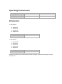
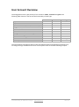
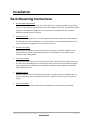
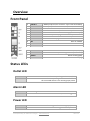
User Manual v3.0 ES2000 Series ES6000 Series EnergySwitch Contents Contents .................................................................................................................................................. 2 Preliminary Information .......................................................................................................................... 5 Introduction......................................................................................................................................... 5 Applicable Models ............................................................................................................................... 6 Specifications....................................................................................................................................... 7 Overview.......................................................................................................................................... 7 Operating Environment ................................................................................................................... 8 Dimensions ...................................................................................................................................... 8 User Account Overview ................................................................................................................... 9 CLI Specifications ........................................................................................................................... 10 Safety ................................................................................................................................................. 11 Certifications ................................................................................................................................. 12 Compliance .................................................................................................................................... 12 Recycling ............................................................................................................................................ 13 Servicing & Repair ............................................................................................................................. 13 Additional Documentation ................................................................................................................ 13 Getting Started .................................................................................................................................. 14 Receiving Inspection ...................................................................................................................... 14 Inventory ....................................................................................................................................... 14 Installation ............................................................................................................................................. 15 Rack Mounting Instructions .............................................................................................................. 15 Mounting the EnergySwitch .............................................................................................................. 16 Additional Earthing ............................................................................................................................ 16 Connecting the EnergySwitch............................................................................................................ 16 Overview................................................................................................................................................ 17 Front Panel ........................................................................................................................................ 17 Status LEDs ........................................................................................................................................ 17 Outlet LED...................................................................................................................................... 17 Alarm LED ...................................................................................................................................... 17 Power LED...................................................................................................................................... 17 Quick Configuration............................................................................................................................... 18 Using the Display ............................................................................................................................... 18 Activating the Display .................................................................................................................... 18 Controlling the Display .................................................................................................................. 18 Hot Keys ......................................................................................................................................... 18 © 2011 Racktivity NV Antwerpsesteenweg 19 - 9080 Lochristi - Belgium - www.racktivity.com 2/52 v 2014.3.27 Network Settings ............................................................................................................................... 19 Dynamic IP Address Assignment ................................................................................................... 19 Manual IP Address Assignment ..................................................................................................... 20 Web Interface ........................................................................................................................................ 22 Getting Started .................................................................................................................................. 22 Supported Web Browsers ............................................................................................................. 22 Logging in....................................................................................................................................... 22 Layout ................................................................................................................................................ 23 Tabs ................................................................................................................................................... 24 Power tab ...................................................................................................................................... 24 Environment tab ............................................................................................................................ 24 Logging tab .................................................................................................................................... 24 E2Sensors tab ................................................................................................................................. 24 Settings tab .................................................................................................................................... 25 Device Settings .................................................................................................................................. 25 Network Settings ............................................................................................................................... 26 SNMP Settings ................................................................................................................................... 26 Global ............................................................................................................................................ 27 Authentication Profiles .................................................................................................................. 27 Traps .............................................................................................................................................. 28 Power Settings................................................................................................................................... 28 Startup Delay ................................................................................................................................. 28 Priority ........................................................................................................................................... 28 Overheat Protection ...................................................................................................................... 29 Thresholds ......................................................................................................................................... 29 Resetting Measurements .................................................................................................................. 31 Network Time Protocol (NTP) ........................................................................................................... 31 CLI .......................................................................................................................................................... 32 Connecting......................................................................................................................................... 32 Daisy Chaining ....................................................................................................................................... 34 Principles ........................................................................................................................................... 34 Modes ............................................................................................................................................ 34 Important Notes ............................................................................................................................ 35 Limitations ..................................................................................................................................... 35 Setup.................................................................................................................................................. 36 Cabling ........................................................................................................................................... 36 Assigning Modes............................................................................................................................ 36 Restore .............................................................................................................................................. 37 © 2011 Racktivity NV Antwerpsesteenweg 19 - 9080 Lochristi - Belgium - www.racktivity.com 3/52 v 2014.3.27 UPS Integration ..................................................................................................................................... 38 Configuration ..................................................................................................................................... 38 Compatible Devices ....................................................................................................................... 38 Connecting the UPS ....................................................................................................................... 38 Enabling the Link ........................................................................................................................... 40 Operation .......................................................................................................................................... 40 Rules .................................................................................................................................................. 41 Agent Communication........................................................................................................................... 42 Configuration ..................................................................................................................................... 42 Agent Service ................................................................................................................................. 42 EnergySwitch Configuration .......................................................................................................... 45 Logging .................................................................................................................................................. 47 Event Log ........................................................................................................................................... 47 Management Information Base (MIB) .................................................................................................. 48 Upgrade Firmware................................................................................................................................. 49 Obtaining Files ................................................................................................................................... 49 Troubleshooting .................................................................................................................................... 50 Rebooting the device without interrupting the power ..................................................................... 50 Downloading the diagnostics ............................................................................................................ 50 Resetting Login Credentials ............................................................................................................... 50 Connecting to the Web Interface ...................................................................................................... 50 Knowing your EnergySwitch’ IP Address ........................................................................................... 51 Outlet dialog only shows ON and CYCLE ........................................................................................... 51 Support .................................................................................................................................................. 52 © 2011 Racktivity NV Antwerpsesteenweg 19 - 9080 Lochristi - Belgium - www.racktivity.com 4/52 v 2014.3.27 Preliminary Information Introduction The EnergySwitch PDU Family, EnergyOS and its included EnergyDNA deliver power within the data center along with the energy utilization and capacity optimization features you demand. These next-generation PDUs are a step into the future of data center energy management, leveraging leading-edge EnergyDNA for highly granular visibility into rack-based energy quality and consumption. Main Features: Real-Time, True RMS measurements Metered and switched per outlet Role-based Authentication Event Logging Instant-On technology Physical and logical current protection Sequential outlet startup Programmable thresholds and alarms Support for Racktivity’s E2Sensor family Flash upgradable Ultra-low power consumption © 2011 Racktivity NV Antwerpsesteenweg 19 - 9080 Lochristi - Belgium - www.racktivity.com 5/52 v 2014.3.27 Applicable Models Unless specified otherwise, all information in this document is applicable to the following Racktivity EnergySwitch devices: ES2024-16 ES2024-32 ES2124-30L ES2124-32 ES6024-16 ES6024-20L ES6124-16 ES6124-30L ES6124-32 © 2011 Racktivity NV Antwerpsesteenweg 19 - 9080 Lochristi - Belgium - www.racktivity.com 6/52 v 2014.3.27 Specifications Overview Voltage Frequency Input, total: CE Input, total: cULus Phase(s) C13 Outlets (#) C19 Outlets (#) Output, bank: CE Output, bank: cULus Output, outlet: C13 Output, outlet: C19 Circuit breaker: 20A ES2024-16 200V - 240V 50/60Hz 16A 1Φ 24 0 16A 8A Thermal ES2024-32 200V - 240V 50/60Hz 32A 1Φ 24 0 20A 8A Thermal ES2124-30L 200V - 240V 50/60Hz 30A 24A 1Φ 21 3 20A 16A 8A 16A Magnetic ES2124-32 200V - 240V 50/60Hz 32A 1Φ 21 3 20A 8A 16A Magnetic ES6024-16 200V - 240V 50/60Hz 16A 3Φ 24 0 16A 8A Thermal ES6024-20L 200V - 240V 50/60Hz 20A 16A 3Φ 24 0 20A 16A 8A Thermal ES6124-16 200V - 240V 50/60Hz 16A 3Φ 21 3 16A 8A 16A Magnetic ES6124-30L 200V - 240V 50/60Hz 30A 24A 3Φ 21 3 20A 16A 8A 16A Magnetic ES6124-32 200V - 240V 50/60Hz 32A 3Φ 21 3 20A 8A 16A Magnetic The model number, input ratings, output ratings and certification information for your EnergySwitch are also shown on the label found on the case of the unit. Operating Environment Operating temperature Storage temperature Humidity 0°C to 50°C -10°C to 60°C 5% to 85% RH 32°F to 122°F 14°F to 140°F non-condensing Dimensions For the models: ES2024-16 ES2024-32 ES6024-16 ES6024-20L Dimensions cm (WxHxD) Dimensions inch (WxHxD) 5 x 171 x 9 2 x 67.3 x 3.5 For the models: ES2124-30L ES2124-32 ES6124-16 ES6124-30L ES6124-32 Dimensions cm (WxHxD) Dimensions inch (WxHxD) 5 x 181 x 9 2 x 71.3 x 3.5 Some newer models may exceed these dimensions in height, please contact Support for exact specifications. User Account Overview The EnergySwitch has 3 types (levels) of user accounts: admin, restricted and guest. The following table shows an overview of the functionality of each type: Open website Open CLI session View current status (states, data & values) Toggle outlets Edit thresholds Edit outlet names Change SNMP notification settings Edit device settings View & download logs Default user name Default password admin Yes Yes Yes Yes Yes Yes Yes Yes Yes admin 1234 restricted Yes Yes Yes Yes No No No No No restricted 1234 guest Yes Yes Yes No No No No No No guest 1234 The same features and options apply to both the website and the Command Line Interface (CLI). To change the login credentials for a user account please refer to the Device Settings chapter. © 2011 Racktivity NV Antwerpsesteenweg 19 - 9080 Lochristi - Belgium - www.racktivity.com 9/52 v 2014.3.27 CLI Specifications The CLI connector on the EnergySwitch has the following pin lay-out (as seen on the male plug): Pin 1 2 3 4 5 6 7 8 Function TxD GND GND RxD - Compatibility The following brands/devices can be connected directly to the RS232 ports of the EnergySwitch using a standard straight-through RJ45 patch cable (unless noted otherwise): Cisco Cisco devices that have a Console which uses the pin lay-out of the 72-3383-01 Management cable (RJ45 - DB9) Hewlett-Packard HP devices that have a Console which uses the pin lay-out of the 5188-3836 Console cable (RJ45 - DB9) require that Pin3 (RxD) and Pin6 (TxD) are switched Fortinet Depending of the model, Fortinet devices either require that Pin3 (RxD) and Pin6 (TxD) are switched or can be connected using a standard patch cable © 2011 Racktivity NV Antwerpsesteenweg 19 - 9080 Lochristi - Belgium - www.racktivity.com 10/52 v 2014.3.27 Safety Save these instructions! This Safety Information contains important instructions that should be followed during installation and maintenance of the EnergySwitch. It is intended for Racktivity customers who set up, install, relocate, or maintain Racktivity equipment. Changes and modifications to this unit not expressly approved by Racktivity could void the warranty. Electrical Hazard! Read the following information before installing or operating your EnergySwitch: Do not work alone under hazardous conditions. High current through conductive materials could cause severe burns. Follow all local and national codes when installing the EnergySwitch. To avoid possible electrical shock and equipment damage, use only the supplied hardware. The EnergySwitch should be connected to a single-outlet dedicated circuit, protected by a circuit breaker with the same current rating as the EnergySwitch. The plug serves as the disconnect for the EnergySwitch. Make sure the utility power outlet for the EnergySwitch will be close to the EnergySwitch and readily accessible. Make sure the utility power outlet and the EnergySwitch power cord and plug are in good condition. Do not connect the EnergySwitch to an ungrounded utility power outlet. Do not operate your EnergySwitch with any covers removed or when it is damaged. This EnergySwitch contains potentially hazardous voltages. There are no user serviceable parts inside the EnergySwitch. All repairs and service should be performed by authorized service personnel only. The power requirement for each piece of equipment connected to the EnergySwitch must not exceed the individual outlet’s load rating. The EnergySwitch provides convenient multiple power outlets, but it does not provide surge or line noise protection for connected equipment. The EnergySwitch is designed for indoor use only in a controlled environment away from excess moisture, temperature extremes, conductive contaminants, dust, direct sunlight or magnetic sources. The total power requirement for equipment connected to the EnergySwitch must NOT exceed the maximum load rating for the EnergySwitch. Do not attempt to mount the EnergySwitch to an insecure or unstable surface. Never attempt to install electrical equipment during a thunderstorm. Use of this equipment in life support applications or any medical applications is strictly prohibited since failure of this equipment can reasonably be expected to cause the failure of the life support equipment or to significantly affect its safety. Putting several EnergySwitch units in cascade is NOT allowed. © 2011 Racktivity NV Antwerpsesteenweg 19 - 9080 Lochristi - Belgium - www.racktivity.com 11/52 v 2014.3.27 CAUTION: The EnergySwitch contains a lithium battery and should not be disposed of with general refuge. Dispose of the lithium battery in accordance with all local codes and regulations for products containing lithium batteries. Contact your local environmental control or disposal agency for further details. The battery is not intended to be user replaceable. Certifications Not all certifications are applicable to every model. Please check the label on your device. CE / FCC This device is designed in compliance with the requirements of the 4 following regulations: EN 55022: Class B, EN 61000-3-2, EN 6100-3-3 and EN 55024. This device is certified to comply with Part 15 of the FCC rules. UL (US & Canada) This device is in the certification process to comply with rule UL /CSA 60950-1 (2nd Edition) safety of Information Technology Equipment (ITE) Part 1. Compliance WEEE Waste Electrical and Electronic Equipment RoHS Restriction of Hazardous Substances © 2011 Racktivity NV Antwerpsesteenweg 19 - 9080 Lochristi - Belgium - www.racktivity.com 12/52 v 2014.3.27 Recycling The materials used for shipping the EnergySwitch are recyclable, please save them for later use or dispose of them appropriately. Servicing & Repair There are no user serviceable parts inside the EnergySwitch. All repairs and service should be performed by authorized service personnel only. Please refer to the Service manual for RMA procedure. Additional Documentation Additional documentation regarding the following subjects is available on the Racktivity Support Website http://www.racktivity.com/support/. API o Manual o GUID Overview o (python) examples 2 E Sensor User Manual Servicing (RMA) © 2011 Racktivity NV Antwerpsesteenweg 19 - 9080 Lochristi - Belgium - www.racktivity.com 13/52 v 2014.3.27 Getting Started Receiving Inspection Inspect the package (see the Inventory chapter) and contents for shipping damage and make sure that all parts were received. Report any damage immediately to the shipping agent and report missing contents, damage, or other problems immediately to your reseller. Inventory Please verify the contents of the box: Standard Package Item EnergySwitch Mounting bracket set (screws) - flat Mounting bracket set (screws) - angle Mounting bracket set (button mount) - flat Mounting bracket set (button mount) - angle Mounting bracket screws Retention brackets Quick Start Guide Quantity 1 1 1 1 1 4 24 1 © 2011 Racktivity NV Antwerpsesteenweg 19 - 9080 Lochristi - Belgium - www.racktivity.com 14/52 v 2014.3.27 Installation Rack Mounting Instructions Elevated Operating Ambient When installed in a closed or multi-unit rack assembly, the operating ambient temperature of the rack environment may be greater than room ambient. Therefore, consideration should be given to installing the equipment in an environment compatible with the maximum ambient temperature (Tma) of 50 ºC. Reduced Air Flow Installation of the equipment in a rack should be such that the amount of air flow required for safe operation of the equipment is not compromised. It is recommended that 2.5cm (1 inch) of clearance be supplied around the sides of the unit. Mechanical Loading Mounting of the equipment in the rack should be such that a hazardous condition is not achieved due to uneven mechanical loading. The unit should be mounted with screws suitable for up to 10kg (22lbs). Circuit Overloading Consideration should be given to the connection of the equipment to the supply circuit and the effect that overloading of the circuits might have on overcurrent protection and supply wiring. Appropriate consideration of equipment nameplate ratings should be used when addressing this concern. Reliable Earthing Reliable earthing of the unit should be maintained. Particular attention should be given to supply connections other than direct connections to the branch circuit (e.g. use of power strips). Outlet accessibility The socket-outlet shall be installed near the equipment and shall be easily accessible. © 2011 Racktivity NV Antwerpsesteenweg 19 - 9080 Lochristi - Belgium - www.racktivity.com 15/52 v 2014.3.27 Mounting the EnergySwitch 1. Attach the 2 mounting brackets to the back of the EnergySwitch using the provided screws. The brackets may be positioned for mounting on either side of the rack. 2. Attach the PDU to a vertical rail in your rack or rack enclosure. (Use the mounting hardware that came with your rack or rack enclosure to attach the mounting brackets to the rail.) Additional Earthing The metal case of the EnergySwitch is electrically bonded to the line cord ground wire. A threaded grounding point on the front of the case may be used as an additional means of protectively grounding this product and the rack. Connecting the EnergySwitch 1. For North America Connect the NEMA input plug to a compatible NEMA outlet receptacle. For Europe and other countries using IEC 309 based power receptacles, connect to the IEC 309 receptacle compatible to the IEC 309 cord plug provided. Note: The AC power source should not share a circuit with a heavy electrical load. It is recommended that the EnergySwitch be connected to a dedicated branch circuit. 2. The POWER LED (blue) will become active. 3. When using the device for the first time all OUTPUT LEDs will light up consecutively indicating that the outlets are being activated. Connect your equipment’s input plugs to the outlet plugs of the EnergySwitch. © 2011 Racktivity NV Antwerpsesteenweg 19 - 9080 Lochristi - Belgium - www.racktivity.com 16/52 v 2014.3.27 Overview Front Panel 1 2 3 4 5 6 7 8 9 10 11 R-BUS A R-BUS B CLI LAN TFT UP MENU DOWN OK ALARM LED POWER LED - OUTLET FUSE EARTH INLET RS485 peripheral bus connector A (for external modules) RS485 peripheral bus connector B (for external modules) RS232 Command Line Interface connector Ethernet connector (with connectivity indicator LEDs) Color graphics TFT display Move to the previous page or to browse upwards in a list Access menu function or return to the previous screen Move to the next page or to browse downwards in a list Enter or validate Alarm LED Power LED Outlet banks with connectors (C13, C19, …) Fuse (see labeling for fuse specifications) Device earthing (M5) Inlet plug Status LEDs Outlet LED ON OFF The corresponding outlet is turned on The corresponding outlet is turned off and the connected device is not receiving input power Alarm LED ON OFF Warning, at least one alarm: visit the Web Interface for more info OK, no alarms triggered Power LED ON OFF The EnergySwitch is receiving input power The EnergySwitch is unpowered © 2011 Racktivity NV Antwerpsesteenweg 19 - 9080 Lochristi - Belgium - www.racktivity.com 17/52 v 2014.3.27 Quick Configuration Using the Display Activating the Display When the Power LED is lit and the screen is black, push any of the 4 navigation buttons next to the Display to activate it. The Display timeout delay can be set at the Device Settings page on the Web Interface (the default value is 10 minutes). Controlling the Display The Display is controlled using the UP, DOWN, MENU and OK buttons next to the screen. Use the UP and DOWN buttons to navigate through the reporting screens or through a selection list in the menus. Press OK to select the highlighted item and MENU to go back. When in a menu, the ">" symbol indicates that clicking this item will open a submenu. The "●" symbol indicates that this menu item leads directly to a setting. Hot Keys Several Hot Key combinations are available by using the navigation buttons next to the display. To activate the functions, press the necessary buttons simultaneously for 4 seconds (until the notification is shown on screen). Hot Key Buttons Hot Reset MENU + DOWN Credential Reset UP + DOWN Factory Reset MENU + OK Action Reboots the master/controller module (not the power modules/banks) No outlets toggled, no settings changed Resets the login credentials No outlets toggled, login credentials set to default Resets all non-power related settings (except Line Current and Fuse Current thresholds) to factory defaults (network, SNMP configuration, credentials, etc.), no outlets are toggled. Use the CLI to reset the individual power modules (banks) instead. Note: When the Display Lock setting is enabled these Hot Keys will not be triggered. © 2011 Racktivity NV Antwerpsesteenweg 19 - 9080 Lochristi - Belgium - www.racktivity.com 18/52 v 2014.3.27 Network Settings There are two methods for setting up the IP address: Dynamic IP address assignment and Manual Assignment. If you are uncertain which method to use, contact your network administrator for assistance before continuing the installation process. Dynamic IP Address Assignment Note: Dynamic IP address assignment is enabled by default. 1. Press the MENU button until the MAIN menu appears, select Settings using the DOWN button and press OK. Actual display layout may vary slightly 2. Select Network and press OK. 3. Within the Network Settings menu, select DHCP. When the value at the bottom of the screen shows Enabled, the device already has dynamic IP assignment enabled (skip to step 4). If not, press OK and verify that Enabled is displayed at the bottom of the screen. 4. Use the UP button to select Apply Settings and press OK. Press the MENU button to cancel or the OK button to apply the settings. © 2011 Racktivity NV Antwerpsesteenweg 19 - 9080 Lochristi - Belgium - www.racktivity.com 19/52 v 2014.3.27 5. Press DOWN to select IP Address. The assigned IP-address is shown at the bottom. 6. On a computer in the same network, use a browser to open the assigned IP-address, for example https://192.168.14.250 7. When surfing to the web portal, a login screen appears. The default user name is admin and the default password is 1234 Manual IP Address Assignment 1. Obtain the correct IP address, standard gateway, DNS Server IP and subnet mask from your network administrator. 2. Press the MENU button until the MAIN menu appears, select Network Settings using the DOWN button and press OK. 3. Within the Network Settings menu, select DHCP. When the value at the bottom of the screen shows Disabled, the device already has manual IP assignment enabled (skip to the next step to enter a different IP). If not, press OK and verify that Disabled is displayed at the bottom of the screen. © 2011 Racktivity NV Antwerpsesteenweg 19 - 9080 Lochristi - Belgium - www.racktivity.com 20/52 v 2014.3.27 4. Use the UP button to select IP Address and press OK. 5. Use the UP and DOWN buttons to change the currently selected value and press OK to select the next value. When holding the UP and DOWN buttons changing the values speeds up. When ready press MENU to confirm and return to the Network Settings menu. 6. Repeat the last two steps for the Subnet Mask, Standard Gateway and DNS Server settings. 7. Use the UP button to select Apply Settings and press OK. Press the MENU button to cancel or the OK button to apply the settings. 8. On a computer in the same network, use a browser to open the chosen IP-address, for example https://192.168.14.250 When surfing to the Web Interface, a popup appears requesting a username and password. The default username is admin and the default password is 1234 Note: Using the WattsInsight functionality together with Manual IP Address Assignment requires IP Address, Subnet Mask, Standard Gateway and DNS Server to be filled in correctly. © 2011 Racktivity NV Antwerpsesteenweg 19 - 9080 Lochristi - Belgium - www.racktivity.com 21/52 v 2014.3.27 Web Interface Getting Started Supported Web Browsers The following browsers have been tested and work with the EnergySwitch’ Web Interface (on most platforms): Internet Explorer 11 or higher Firefox 26.0 or higher Chrome 31.0 or higher Opera 12.11 or higher Other available web browsers may work with the EnergySwitch but have not been fully tested by Racktivity. Logging in For instructions on how to set up the TCP/IP settings to connect to the Web Interface, please see the Network Settings chapter. To recover from a lost password, please refer to the Troubleshooting chapter. Use an internet browser to open the EnergySwitch’ IP address. You will be asked for login credentials, the default values for the administrator account are: User name Password admin 1234 To find out everything about the different types of user accounts see the User Account Overview chapter. Due to the nature of the default secure connection (HTTPS) and the workings behind authentication certificates, any warnings regarding the connection (self-signed certificate) can be ignored. © 2011 Racktivity NV Antwerpsesteenweg 19 - 9080 Lochristi - Belgium - www.racktivity.com 22/52 v 2014.3.27 Layout 1 2 3 4 Sub tabs User account Main tabs Device info 5 Outlet status 6 7 8 9 10 Outlet toggle Reset Save SNMP Device time 11 12 Banks Daisy chain Displays the different subtabs of the selected main tab Displays which type of User Account is currently logged in Displays the different functions of the EnergySwitch Displays the device name, rack name & rack location. Can be changed at the Settings tab Displays the current status of each outlet: GREY: the outlet is turned off GREEN: the outlet is on and working normally ORANGE: a warning threshold has been crossed, but the outlet was not toggled off RED: an off threshold has been crossed, outlet was toggled off BLUE: the outlet will be toggled after the set delay has expired (during boot and whilst power cycling) Toggle the outlet state (ON/OFF/CYCLE) Resets the values on the tab to the values saved in the device Save any changes made on this tab Toggle a specific SNMP notification for that outlet The UTC/GMT time set on the Settings tab (either manual or through an NTP server) Power module/bank selection Daisy chain device selector (Master, Slave 1, Slave 2, Slave 3) © 2011 Racktivity NV Antwerpsesteenweg 19 - 9080 Lochristi - Belgium - www.racktivity.com 23/52 v 2014.3.27 Tabs Power tab Use the Power tab for the following: See the load and general status of both the EnergySwitch’s individual outlets and the totals: o Current (A) o Power (W) o Power Factor (%) o Energy (kWh) o Apparent Energy (kVAh) o Voltage (V) Control and manage outlets Configure thresholds for connected loads, banks (as applicable) Resetting measurements Change SNMP notifications for power related parameters (outlet toggle, current, power, etc.) Manage outlet scheduling Control fuse and/or line currents View electrical topology of the device Oscilloscope view for an outlet Overview of connected Agents Environment tab Use the Environment tab to monitor and manage: Internal temperature sensors Voltage (V): status, history and management Frequency (Hz) Logging tab The logging tab provides access to the Event logging. After selecting the desired module and time-range the log can be downloaded or viewed inside the browser (see the Logging chapter). E2Sensors tab Use this tab to manage and monitor your E2Sensors. For more information regarding this tab, please see the E2Sensor documentation. © 2011 Racktivity NV Antwerpsesteenweg 19 - 9080 Lochristi - Belgium - www.racktivity.com 24/52 v 2014.3.27 Settings tab Use this tab to configure the following settings: Device (see Device Settings chapter) Network (see Network Settings chapter) SNMP (see SNMP Settings chapter) Power (see Power Settings chapter) Daisy Chain (see the Daisy Chaining chapter) Uninterruptible Power Supply (see UPS Integration chapter) WattsInsight Device Settings Path: Settings > Device The Device Settings give access to: Device identification o Device name: the name of the device o Rack name: the name of the rack where the device is located o Rack position: the identifier of the position in the rack User account settings (see the User Account Overview chapter) o Admin: Name and password for the admin account o Restricted user: Name and password for the restricted account o Guest: Name and password for the guest account System reboot o Reboot device: Pressing this button will hot reset the device (no outlets states will be changed) Display settings o Display timeout: the idle time in minutes after which the Display goes into standby o Display lock: when enabled the display (and buttons) cannot be used to change settings (display becomes read-only). All changes must be made through the other available interfaces Temperature o Temperature unit: degrees Celsius (°C) or Fahrenheit (°F) Web Interface o Website auto logout: The time in minutes after which the session expires Clock settings (see the Network Time Protocol (NTP) chapter) o Date & Time Settings: The real-time clock dialog features several options: Uncheck the Use NTP checkbox to be able to set a custom date & time Uncheck the Use default NTP checkbox to not use an NTP server from pool.ntp.org and enter the custom IP address into the NTP address field Note: Making changes to the date/time settings will clear all Logging! System info o About this device: Shows all relevant firmware and hardware info regarding your device. Please provide this info when communication with Racktivity Support © 2011 Racktivity NV Antwerpsesteenweg 19 - 9080 Lochristi - Belgium - www.racktivity.com 25/52 v 2014.3.27 Network Settings Path: Settings > Network The Network subtab contains the Network and other security settings. The following Network settings are available: MAC Address o The MAC address of the EnergySwitch Enable DHCP o Toggle DHCP (depending on this setting the fields below it will be enabled or disabled) Device IP Address o The IP address of the EnergySwitch Subnet Mask o The subnet mask of the EnergySwitch Standard Gateway o The IP address of the default node on the network DNS Server o The IP address of the Domain Name System (DNS) server Test Connection o Ping a device on the network to test network settings. Note: Save any changed settings before using this functionality. ECS (Energy Cloud Sentinel) o For more info on the ECS functionality please refer to the ECS documentation. Force secure web access (HTTPS) o Check to force secure HTTP web access Force secure Telnet access (SSL) o Check to force Telnet-SSL access SNMP Settings Path: Settings > SNMP The EnergySwitch offers SNMPv2c and SNMPv3 communication (GETs, SETs and traps). Notifications (traps) can be enabled or disabled for many of the device’s functions: Outlet state change Outlet thresholds (current, power, …) Totals thresholds (current, power, …) Temperature thresholds Voltage thresholds Overheat protection … To toggle SNMP for a specific parameter or function, (un)check that parameter’s checkbox and press the Save button. The SNMP checkboxes can be found next to most measurements. © 2011 Racktivity NV Antwerpsesteenweg 19 - 9080 Lochristi - Belgium - www.racktivity.com 26/52 v 2014.3.27 The SNMP subtab is divided into 3 sections: Global, Authentication Profiles and Traps. Global The Global section of the SNMP subtab contains the following settings: Allow SNMPv2c GET & SET o Toggles communication to and from the device using SNMPv2c Note: SNMPv2c Traps can still be used when this setting is disabled (see Traps chapter) Allow SNMPv3 GET & SET o Toggles communication to and from the device using SNMPv3 Note: SNMPv3 Traps can still be used when this setting is disabled (see Traps chapter) Write Protection (SNMP read-only) o With this setting enabled the device will not accept changes and SET requests over SNMPv2c or SNMPv3. GET, Walk, etc. requests are still allowed Enable SNMP Traps o When enabled, no SNMP Traps will be sent (even when all other SNMP settings are configured correctly) Heartbeat Interval o Defines the interval (in seconds) at which Heartbeat SNMP Traps will be sent to the configured receivers. Set to 0 to disable this feature Download MIB file o The MIB files for your device, more info in the Management Information Base (MIB) chapter Authentication Profiles The authentication profiles section is used to configure the available SNMP profiles for GET & SET access. At this time the following profiles are available: SNMPv2c o 1 profile o Requires community strings (read, write and trap) SNMPv3 o 3 profiles available o The SNMPv3 profiles require all of the following parameters: USM User Authentication passphrase (auth): MD5 In text or hexadecimal format Privacy passphrase (priv): AES In text or hexadecimal format Note: Some SNMP monitoring tools will require the SNMPv3 Engine ID displayed in this section. © 2011 Racktivity NV Antwerpsesteenweg 19 - 9080 Lochristi - Belgium - www.racktivity.com 27/52 v 2014.3.27 Traps In the Traps section up to 3 SNMP Trap receivers can be configured. Each receiver contains the following: Enable o Enable or disable this receiver IP Address o The IP address of the receiver Port o The network port on the receiver to use Authentication profile o The authentication profile used to authenticate with the Trap receiver Send test SNMP Trap o Sends a Heartbeat Trap to all configured SNMP Trap receivers Note: Save any changed settings before using the button Note: This button is disabled when SNMP Traps are disabled in the Global section Power Settings Startup Delay Path: Settings > Power The startup delay shown in the table is the time in seconds at which the designated outlet will switch on after boot. By default the delay is set incrementally over the outlets to reduce the overall power peaks of booting loads. Note: An outlet will only switch on at boot if it was on before the EnergySwitch was powered down. Priority Path: Settings > Power The Importance column gives a rating from 1 to 8 to each outlet. A rating of 1 indicates the highest importance, whilst 8 is the lowest. When the Total (device) off threshold for the current and/or power is crossed (but none of the individual off thresholds) the EnergySwitch will use the importance rating to determine which outlet to switch off first. © 2011 Racktivity NV Antwerpsesteenweg 19 - 9080 Lochristi - Belgium - www.racktivity.com 28/52 v 2014.3.27 If two or more outlets have the same rating, the outlet with the last peak load will be switched off first. Overheat Protection Path: Settings > Power The EnergySwitch has built in temperature sensors that can help prevent overheating. For more information regarding the thresholds and event notifications please refer to the Error! Not a valid bookmark self-reference. and SNMP Settings chapters. Note: The EnergySwitch has a built-in safety that switches off all outlets when the temperature hits 60°C (140°F) regardless of the settings in the Overheat Protection section. Thresholds Thresholds can be configured and used so that you are notified through SNMP at certain events. These events are also logged in the Event Logging. Many of the EnergySwitch’s parameters have settable thresholds. To configure a specific threshold, open the tab where the appropriate parameter is shown. At least the following parameters have one or more settable thresholds: Current (A) o Path: Power > Current Power (W) o Path: Power > Power Fuse o Path: Power > Fuse Voltage (V) o Path: Environment > Electrical Ambient o Path: Environment > Ambient E2Sensors (when connected) o Path: E2Sensors Overheat Protection o Path: Settings > Power UPS (when enabled) o Path: Settings > UPS © 2011 Racktivity NV Antwerpsesteenweg 19 - 9080 Lochristi - Belgium - www.racktivity.com 29/52 v 2014.3.27 Depending on the parameter one or more of the following types of thresholds will be available: Warning: The outlet state is not changed, only an SNMP notification is sent Switch Off: The designated outlet is toggled off and an SNMP notification is sent. The outlet’s status LED will turn red. Low: When the measurement goes below this value an SNMP notification is sent High: When the measurement goes above this value an SNMP notification is sent To change a threshold enter the desired value into the appropriate input area and press the Save button. If the background of the input area turns red an incorrect value has been entered. To see which values are accepted, hover your cursor over the now red input area and a tooltip will appear with detailed information. Note: Most thresholds have corresponding SNMP checkboxes that enable/disable the notification. Please ensure both the threshold and the appropriate SNMP notifications are set correctly. © 2011 Racktivity NV Antwerpsesteenweg 19 - 9080 Lochristi - Belgium - www.racktivity.com 30/52 v 2014.3.27 Resetting Measurements For many parameters the minimum, maximum and/or total is saved to give an easy overview of load activity. These values can be easily reset by pressing the Reset link for that value. The following parameters have resettable values: Individual & total current o Path: Power > Current Individual & total power o Path: Power > Power Individual & total power factor o Path: Power > Power Individual & total real energy o Note: The Accumulated kWh counter is not resettable! o Path: Power > Energy Individual & total apparent energy o Note: The Accumulated kVAh counter is not resettable! o Path: Power > Energy Temperature o Path: Environment > Ambient Voltage o Path: Environment > Electrical E2Sensor read-outs (depending on model) o Path: E2Sensors Note: Clicking a Reset link in the column header will reset all values in that column, except for the value in the Total row. Network Time Protocol (NTP) Path: Settings > Device The Network Time Protocol (NTP) is a protocol for synchronizing the clocks of computer systems over networks. The EnergySwitch is equipped with an onboard clock that can be setup to sync with: pool.ntp.org (default) a custom NTP server date & time picker For more information regarding the configuration of the onboard clock please refer to the Device Settings chapter. © 2011 Racktivity NV Antwerpsesteenweg 19 - 9080 Lochristi - Belgium - www.racktivity.com 31/52 v 2014.3.27 CLI The EnergySwitch has a built in Command Line Interface (CLI) that can be accessed through both the CLI connector on the front or via Telnet. Commands are typically sent to the separate modules. An EnergySwitch typically consists of 1 “Master” module and 1 or more “Power” modules, controlled by the master. Each module is of a specific type: M for master module P for power module A for E2Sensor The master typically has address M1, power modules can have addresses P1 (Outlets 1-8), P2 (Outlets 9-16), P3 (Outlets 17-24)… Connecting CLI connector Connect a standard cat. 5e patch cable to both the CLI connector and your pc (i.e. by using an RS232 to USB adapter). For the CLI Specification, see the CLI Specifications chapter. Connection settings: 115200/8-N-1 (115200Bd, 8 data bits, no parity, 1 stop bit) Telnet Connect to the device IP on port 23 over Telnet using a 3rd party tool (i.e. Putty). Please note that only Telnet over SSL is enabled by default. This can be changed on the Settings > Network subtab on the Web Interface of the device. Telnet-SSL Connecting to Telnet over SSL can be achieved through several 3rd party tools. For example using stunnel (cross platform): Edit the configuration file for stunnel called stunnel.conf so it contains only the following: fips = no cert = stunnel.pem client = yes [pdu] accept = 127.0.0.1:23 connect = [DEVICE_IP]:992 sslVersion = SSLv3 (with [DEVICE_IP] being the IP address of the PDU) Start stunnel with this config: # stunnel stunnel.conf If you now Telnet to 127.0.0.1 on port 23, stunnel will tunnel the traffic over SSL to the specified IP. © 2011 Racktivity NV Antwerpsesteenweg 19 - 9080 Lochristi - Belgium - www.racktivity.com 32/52 v 2014.3.27 Once connected, you will be presented with a log-in screen. Use the admin credentials to gain full access. From here it is possible to access the majority of the EnergySwitch’s functions. Execute the “HELP” command for more information. © 2011 Racktivity NV Antwerpsesteenweg 19 - 9080 Lochristi - Belgium - www.racktivity.com 33/52 v 2014.3.27 Daisy Chaining Principles Your device features the possibility to set up a daisy chain using 4 Racktivity EnergySwitch PDUs. In this configuration one of the devices is the Master (exactly 1 device) while the other devices are Slaves (up to 3 devices). Monitoring and management of the Slaves can now be obtained through the interfaces of the Master. When in daisy chain all the devices in the chain remain accessible on their individual IP interface over the network. Daisy chain setups are typically used to reduce the number of IP addresses needed for operational equipment. A standalone non daisy chained device consists of a Master module (which controls the display, network connectivity, etc.) identified with the address "M1" and 1 or more Power modules (which control the individual banks/outlets) identified with “P1” (outlets 1-8) for a 1U device and “P1” (outlets 1-8), “P2” (outlets 9-16) or “P3” (outlets 17-24) for a 0U device. To clarify: “Master modules” are internal modules of devices; “Master devices” are the communication entry points for daisy chain setups (which also consist of “Slave devices”). Both are unique in their own setup: 1 Master module per device, and 1 Master device per daisy chain. Modes There are 4 available Modes concerning daisy chaining that define the position of a device within the chain. Modes can be set through the display and Web Interface. Standalone o When in Standalone Mode daisy chaining is disabled Daisy Chain Master o When in this Mode the device is the Master device of the daisy chain setup. Note: Having more than 1 Daisy Chain Master on the daisy chain bus may result in unexpected behavior. o Modules addresses (1U device): Master module: M1 Power modules: P1 (outlets 1-8) o Modules addresses (0U device): Master module: M1 Power modules: P1 (outlets 1-8), P2 (outlets 9-16), P3 (outlets 17-24) Daisy Chain Slave 1 o Devices with this Mode set will be considered the first slave on the bus. o Modules addresses (1U device): Master module: M2 Power modules: P2 (outlets 1-8) o Modules addresses (0U device): Master module: M2 Power modules: P4 (outlets 1-8), P5 (outlets 9-16), P6 (outlets 17-24) © 2011 Racktivity NV Antwerpsesteenweg 19 - 9080 Lochristi - Belgium - www.racktivity.com 34/52 v 2014.3.27 Daisy Chain Slave 2 o Devices with this Mode set will be considered the second slave on the bus. o Modules addresses (1U device): Master module: M3 Power modules: P3 (outlets 1-8) o Modules addresses (0U device): Master module: M3 Power modules: P7 (outlets 1-8), P8 (outlets 9-16), P9 (outlets 17-24) Daisy Chain Slave 3 o Devices with this Mode set will be considered the third (and last) slave on the bus. o Modules addresses (1U device): Master module: M4 Power modules: P4 (outlets 1-8) o Modules addresses (0U device): Master module: M4 Power modules: P10 (outlets 1-8), P11 (outlets 9-16), P12 (outlets 17-24) Important Notes 1. The Mode of each device must be unique in its daisy chain, duplicate Modes will cause unexpected behavior 2. Your Racktivity EnergySwitch must have at least 2 R-BUS connectors for it to be daisy chainable 3. The order in which the cables between the R-BUS connectors on the devices are connected is not tied to the master/slave hierarchy 4. Daisy chaining is only possible for 4 devices of the same product family (0U vs. 1U) running the same firmware version Limitations 1. Racktivity 0U EnergySwitch PDUs cannot be daisy chained with 1U EnergySwitch PDUs and vice versa. 2. A daisy chain can consist of a total of maximum 4 devices. 3. The following features are not available in a daisy chain setup: (M = Master device, S = Slave devices) Oscilloscope View (S) SNMP (S) UPS Integration (M+S) WattsInsight (S) E2Sensors (S) © 2011 Racktivity NV Antwerpsesteenweg 19 - 9080 Lochristi - Belgium - www.racktivity.com 35/52 v 2014.3.27 Setup Setting up a daisy chain can be done using the display or the Web Interface of each device. In the following instructions, a daisy chain setup with 4 devices will be created. Setups with only 2 or 3 devices are also possible; in this case the steps for the second (and/or third) slave device can be omitted. Note: Please read the Principles, Important Notes and Limitations sections of this chapter carefully before continuing with the daisy chain setup process. Cabling Using a standard UTP cat5e patch cable, link the R-BUS connectors from one device to the next. All devices (master & slaves) should be linked in such a way that they are connected on the same "bus". Connectors marked "R-BUS A" and/or "R-BUS B" are interchangeable. Note: Do not create loops between the R-BUS A and R-BUS B connector of the same device. Assigning Modes Display The following steps need to be performed on the display of each device you wish to add as Slave: 1. Press the MENU button until the MAIN menu appears, select Settings using the DOWN button and press OK 2. Select Daisy Chain and press OK 3. Select Device Mode and Press OK 4. For each Slave device: consecutively select Daisy Chain Slave 1, 2 and 3 and press OK The following only needs to be performed on the device that will be used as Master device: 1. Press the MENU button until the MAIN menu appears, select Settings using the DOWN button and press OK 2. Select Daisy Chain and press OK 3. Select Device Mode and Press OK 4. Select Daisy Chain Master and press OK 5. Select Add All Slaves and Press OK © 2011 Racktivity NV Antwerpsesteenweg 19 - 9080 Lochristi - Belgium - www.racktivity.com 36/52 v 2014.3.27 6. All connected devices with their Mode set to Slave will now be added to the list (in yellow) Web Interface The following steps need to be performed on the display of each device you wish to add as slave: 1. Login to the Web Interface and open the Settings > Daisy Chain subtab 2. For each Slave device: consecutively select Daisy Chain Slave 1, 2 and 3 in the Device Mode dropdown list and press the Save button The following only needs to be performed on the device that will be used as Master device: 1. Login to the Web Interface and open the Settings > Daisy Chain subtab 2. Select Daisy Chain Master in the Device Mode dropdown list and press the Save button 3. Press the Scan For Slave Devices button in the Devices section 4. All connected devices with their Mode set to Slave will now be added to the list Whenever a Slave device is disconnected from the bus it will be displayed as Disconnected in the Devices list Slave devices can be removed from the daisy chain by pressing the corresponding Remove link in the Devices list Switching views between the interfaces of the different device in the daisy chain can be done by using the Daisy Chain Device Selector in the top right corner (see Layout chapter). Whenever connection to a Slave device is lost a pop-up will appear. From this point on the daisy chained devices can be controlled using the Web Interface, CLI, etc. of the master device using the correct internal module address. Restore To disable a daisy chain setup, simply reset the Mode of each device to Standalone on the display or through the Web Interface and disconnect any cables between the R-BUS connectors of the devices. For more information on setting Modes see the Assigning Modes chapter. © 2011 Racktivity NV Antwerpsesteenweg 19 - 9080 Lochristi - Belgium - www.racktivity.com 37/52 v 2014.3.27 UPS Integration The UPS integration functionality enables the EnergySwitch to receive vital information from a connected UPS and perform actions when set parameters and rules are met. In order to use the full capabilities of the functionality, 2 components need to be installed and configured correctly: UPS Integration The link with the UPS powering your equipment, as explained in this chapter Agent Communication Communication with the Agent service installed on connected servers/devices (for more details see the Agent Communication chapter) Note: When UPS integration is enabled the CLI connector on the front of the EnergySwitch can no longer be used to access the Command Line Interface. CLI over Telnet remains accessible. To restore CLI functionality over the CLI connector, UPS Integration must be disabled. Configuration Compatible Devices The following UPS models can be linked to your EnergySwitch PDU: Most APC Smart-UPS® models (except Microlink enabled devices) Connecting the UPS The EnergySwitch and the UPS are connected using the following cable configuration: On the side of the EnergySwitch: a standard RJ45 plug (with the pin layout as described in the © 2011 Racktivity NV Antwerpsesteenweg 19 - 9080 Lochristi - Belgium - www.racktivity.com 38/52 v 2014.3.27 CLI Specifications chapter) connected to the CLI connector on the front of the unit. On the side of the UPS: a DB9 male connector. RJ45 Function Tx GND GND Rx DB9 Pin 3 4 5 6 © 2011 Racktivity NV Antwerpsesteenweg 19 - 9080 Lochristi - Belgium - www.racktivity.com Pin 1 Function Rx 9 GND 2 Tx 39/52 v 2014.3.27 Enabling the Link Once the EnergySwitch and UPS are physically connected it is necessary to enable the functionality on the Web Interface of the EnergySwitch. WARNING: If both UPS Integration is enabled and Agent Communication is correctly configured the EnergySwitch will perform automated actions according to strict pre-defined rules (based on battery level, UPS status, etc.). Please review these rules and actions carefully to avoid unexpected behavior! 1. 2. 3. 4. 5. Open the EnergySwitch' Web Interface (see the Web Interface chapter) Open the Settings tab, followed by the UPS subtab Select the appropriate option from the list under Uninterruptible Power Supply (UPS) Press the Save button The UPS subtab will now display the full capabilities of the UPS Integration functionality Operation Once the UPS communication has been configured and established successfully, the following items are available on the Settings > Uninterruptible Power Supply (UPS) sub tab: Communication status o “Up”: The communication between the EnergySwitch and UPS is operational o “Down”: No communication with the UPS, the settings below can be ignored UPS running on battery o “Yes”: The connected UPS is running on battery power (batteries draining) o “No”: The connected UPS is running on mains power (batteries charging) Battery Level The current level of battery power left in the connected UPS (in %), refreshed every 10 seconds. UPS Emergency Threshold The emergency battery level threshold of the connected UPS (in %). When the UPS battery is draining and this level is crossed certain actions will be performed automatically. UPS Recovery Threshold The recovery battery level threshold of the connected UPS (in %). When the UPS battery is charging and this level is crossed certain actions will be performed automatically. UPS Recovery Power Threshold The powered outlets and outlets that have Prevent outlet shutdown enabled on the Power > Agent subtab with respective power consumptions below the recovery power © 2011 Racktivity NV Antwerpsesteenweg 19 - 9080 Lochristi - Belgium - www.racktivity.com 40/52 v 2014.3.27 threshold (in W) will be power cycled when the UPS is running on mains power and the battery level goes above the Battery Recovery Threshold (assuming that the battery level dropped below the Battery Emergency Threshold first). For more information see the Rules chapter. SNMP Warning o Checked: SNMP traps will be sent for all UPS Integration related events o Unchecked: No SNMP traps are sent To enable the EnergySwitch to perform actions based on the UPS Integration data please also refer to the Agent Communication chapter. Rules If both UPS Integration is enabled and Agent Communication is correctly configured the EnergySwitch will perform automated actions according to strict pre-defined rules (based on battery level, UPS status, etc.). Please review the following rules and actions carefully to avoid unexpected behavior. 1. When the EnergySwitch boots, communication with the UPS is OK and the Battery Level is above the UPS Recovery Threshold the outlets will be powered as configured by the user. 2. When the EnergySwitch boots, communication with the UPS is OK and the Battery Level is below the UPS Recovery Threshold only outlets marked with Prevent Outlet Shutdown (see the EnergySwitch Configuration chapter) will be powered. 3. When the EnergySwitch boots and communication with the UPS fails, only outlets marked with Prevent Outlet Shutdown will be powered. 4. When the UPS is running on battery and the Battery Level drops below the UPS Emergency Threshold the EnergySwitch will send a shutdown command to all associated agents. 5. When the communication with the UPS fails for 5 minutes a shutdown command is sent to all associated agents of powered outlets. 6. When the UPS switches from mains to battery power while the Battery Level is below the UPS Emergency Threshold a shutdown command is sent to all associated agents of powered outlets. 7. After the Battery Level dropped below the UPS Emergency Threshold and the UPS is running on mains power again and the Battery Level goes above the UPS Recovery Threshold: All powered outlets and outlets marked with Prevent Outlet Shutdown will be power cycled if their respective power consumptions are below the UPS Recovery Power Threshold. © 2011 Racktivity NV Antwerpsesteenweg 19 - 9080 Lochristi - Belgium - www.racktivity.com 41/52 v 2014.3.27 Agent Communication The Agent Communication functionality enables the EnergySwitch to communicate to installed Agents on connected devices (servers, etc.) and performs actions when set parameters and rules are met. The Agent will also monitor the system it is installed on. In order to use the full capabilities of the functionality, 2 components need to be installed and configured correctly: Agent Communication Communication with the Agent service on connected servers. UPS Integration The link with the connected UPS in the rack (for more details see the UPS Integration chapter). When UPS Integration is not enabled, communication to connected Agents will be limited to manual actions only. Configuration Setting up Agent Communication is a 2-step process: 1. Installing and configuring the Agent service on the connected devices. 2. Configuring the EnergySwitch to communicate to the installed Agent. WARNING: If both UPS Integration is enabled and Agent Communication is correctly configured the EnergySwitch will perform automated actions according to strict pre-defined rules (based on battery level, UPS status, etc.). Please review these rules and actions carefully to avoid unexpected behavior! Agent Service The Racktivity Agent service can be installed on both physical and virtual machines and is used to monitor certain system parameters and to allow the EnergySwitch or the user to perform a graceful shutdown or restart. The system monitoring is performed at a predefined interval (default: 30 seconds) and collapsed every 5 minutes. The collapsed data can be retrieved from the Agent or sent to a predefined URL. This data will allow the Racktivity DCPM platform to provide very detailed and accurate power consumption down to application level. The current version (v1.0) of the Agent service monitors the following: Global CPU usage Total number of processes Top 10 processes according to CPU usage Disks and their storage info: mount point, used bytes, available bytes © 2011 Racktivity NV Antwerpsesteenweg 19 - 9080 Lochristi - Belgium - www.racktivity.com 42/52 v 2014.3.27 Future releases will add the following monitored items: Network interfaces and their info: IP, transmitted bytes, received bytes CPUs and their info: speed, cores, sockets, cores per socket, load All processes and their info: name, CPU usage, memory usage, connections (src IP, src port, dst IP, dst port, duration, amount) Installation The Agent installation package can be obtained by contacting Support and is available for the following operating systems and distributions: Windows Linux Debian After installation, the Agent configuration file (agent.ini) can be found at: Windows C:\Program Files\Racktivity\agent.ini or C:\Program Files (x86)\Racktivity\agent.ini Linux /etc/racktivity/agent.ini Configuration The agent.ini file contains the following sections and editable parameters: MAIN host: The IP on which the Agent listens 0.0.0.0 means listen on any available IP address. Default: 0.0.0.0 port: The port on which the Agent listens Default: 6666 workers: The amount of worker threads that are used to handle the connections. Don’t change this setting Default: 4 allowed: A comma separated list of IPs (cannot contain whitespace characters) that are allowed to communicate with the Agent. If the IP is not in the list the connection is closed instantly. Default: an empty list debug: Whether or not the Agent adds debug information the logs and/or console. Set to 1 to enable. Default: 0 SHUTDOWN url: The URL of the web page that will be called when the shutdown command is received. When this value is left empty the machine on which the Agent is running will be © 2011 Racktivity NV Antwerpsesteenweg 19 - 9080 Lochristi - Belgium - www.racktivity.com 43/52 v 2014.3.27 shut down. When this value is set to 'disabled' no action will be performed. Default: disabled REBOOT url: The URL of the web page that will be called when the restart command is received. When this value is left empty the machine on which the Agent is running will be restarted. When this value is set to 'disabled' no action will be performed. Default: disabled MONITOR interval: The interval (in milliseconds) at which the system is monitored. Default: 30000 pushurls: A comma separated list of URLs that receive the data that is collapsed every 5 minutes. The data is sent in JSON format to the URLs by POST as the data parameter. Default: an empty list backlogsize: The amount of collapsed monitored data points sets that are kept in memory. Default: 6 Additional Commands The following binary commands are accepted by the Agent service: shutdown: Calls the shutdown URL or shuts down the machine (depending on the configuration). Example: shutdown reboot: Calls the reboot url or reboots the machine (depending on the configuration). Example: reboot reconfigure: Sets a configuration parameter on the agent side. Example: reconfigure:shutdown.url=disabledA0B1C2D3E4F5G6H7I8J9 In the example we set the URL parameter of the shutdown section to disabled. "A0B1C2D3E4F5G6H7I8J9" is the SHA1 hash of "reconfigure:shutdown.url=disabled" appended with the IP where the command is coming from. For instance if we send the command from 192.168.1.1 the SHA1 hash is calculated from "reconfigure:shutdown.url=disabled192.168.1.1". configuration: Gets a configuration parameter from the agent. Example: configuration:shutdown.urlA0B1C2D3E4F5G6H7I8J9 In the example we get the URL parameter of the shutdown section. "A0B1C2D3E4F5G6H7I8J9" is the SHA1 hash of "configuration:shutdown.url" appended with the IP where the command is coming from. For instance if we send the command from 192.168.1.1 the SHA1 hash is calculated from "configuration:shutdown.url192.168.1.1". For more information regarding the binary commands, please contact Support. The following HTTP command is also accepted by the Agent service: /getlast5min: Gets the monitored data of the last 5 minutes in a JSON format. Make sure that the IP requesting the command is added to the allowed list of the Agent configuration. Example: http://192.168.14.250:6666/getlast5min © 2011 Racktivity NV Antwerpsesteenweg 19 - 9080 Lochristi - Belgium - www.racktivity.com 44/52 v 2014.3.27 EnergySwitch Configuration Path: Power > Agent The Agent Communication settings on the EnergySwitch can be configured at the Agent subtab. For each outlet the following options are available: State Toggle the state of the outlet. Outlets can be switched on, off or power cycled. Name Change/view the name of the outlet. Prevent Outlet Shutdown When checked the outlet can no longer be toggled off manually, and - with UPS Integration enabled - will be managed differently (see the Rules chapter for more information). Mostly used for vital rack equipment. Agent IP IP of the machine where the Agent for that outlet is installed. Shutdown and/or restart commands will be sent to this IP. Agent Port Network port of the machine where the Agent for that outlet is installed. Agent SNMP Flag Check to send SNMP traps when a command is sent successfully or unsuccessfully. Clean Shutdown Clicking the Shutdown link will send the shutdown command to the Agent configured for that outlet. Restart Clicking the Restart link will send the restart command to the Agent configured for that outlet. © 2011 Racktivity NV Antwerpsesteenweg 19 - 9080 Lochristi - Belgium - www.racktivity.com 45/52 v 2014.3.27 A Shutdown or Restart command can also be sent to an associated agent manually through the use of an HTTP API call (when logged in as administrator): https://[DEVICE_IP]/agent.cgi? ADDR=P[X]&INDEX=[Y]&CMD=[Z] o [DEVICE_IP]: IP of the PDU o [X]: Number of the power module ES1000 Series: 1 (outlets 1-8) ES2000-6000 Series: 1 (outlets 1-8), 2 (outlets 9-16) or 3 (outlets 17-24) o [Y]: Number of the outlet (1 - 8) o [Z]: Command switch: 0 = shutdown command 1 = restart command © 2011 Racktivity NV Antwerpsesteenweg 19 - 9080 Lochristi - Belgium - www.racktivity.com 46/52 v 2014.3.27 Logging The EnergySwitch features an Event Log which can be downloaded from the Web Interface or through the API for your convenience. Event Log Path: Logging > Event The Event Log is used to keep a history of all important events. Fill in the available fields and view the log in your browser or download it for offline use. Module Select the appropriate module Start time The starting date & time for the log End time The ending date & time for the log Download Download the log as a text file Show View the log in your browser The Log is displayed as a table with the following columns (from left to right): Timestamp The timestamp of the event Event type The type of event: outlet toggle, threshold violation … GUID The GUID of the control. For more info regarding GUIDs please refer to the API documentation Value The value that was returned by the event (voltage, temperature, etc.) © 2011 Racktivity NV Antwerpsesteenweg 19 - 9080 Lochristi - Belgium - www.racktivity.com 47/52 v 2014.3.27 Management Information Base (MIB) A management information base (MIB) is a virtual database used for managing the entities in a communications network and is most often associated with the Simple Network Management Protocol (SNMP). The EnergySwitch features a built-in mib file which is available in the following locations: On the Web Interface: Settings > SNMP > Download MIB file On the following URL: https://[DEVICE_IP]/RACKTIVITY-MIB.txt o [DEVICE_IP]: the IP address of your device (i.e.: 192.168.14.250). Use this file to translate the OIDs (Object IDentifiers) available over SNMP to a more humanreadable state. For more information on how to use the MIB file, please refer to the documentation of your network monitoring software. © 2011 Racktivity NV Antwerpsesteenweg 19 - 9080 Lochristi - Belgium - www.racktivity.com 48/52 v 2014.3.27 Upgrade Firmware Racktivity is always working on improving and fine-tuning its products. It is possible that a new firmware is available for your device. During a firmware update the device continues working as normal. Note: Make sure all active connections to the EnergySwitch - such as the website, telnet and SNMP - are closed before updating. Open connections might result in a failed update! Note: Updates are best performed when connected to the device directly Obtaining Files If you are unsure whether a firmware update is available for your device, have a look at http://www.racktivity.com/support or contact Racktivity Support (see Support chapter). If applicable the necessary files and instructions will be provided. © 2011 Racktivity NV Antwerpsesteenweg 19 - 9080 Lochristi - Belgium - www.racktivity.com 49/52 v 2014.3.27 Troubleshooting Rebooting the device without interrupting the power In some cases it might be necessary to restart the device without interrupting the incoming power. To restart the Master module: use the HotReset key combination described in the Hot Keys chapter. This action will only restart the main controller (containing the network interface, display, etc.), not the outlets/banks. To restart the entire device: use the Reboot button on the Web Interface’ Settings > Device subtab. No outlets will be toggled. Downloading the diagnostics It is possible to download a diagnostics file (diag.txt) directly from the device containing a lot of vital system information. To download the file: Login to the Web Interface Change the URL in the address bar to the following and press Enter: https://[DEVICE_IP]/diag.txt Resetting Login Credentials In case of lost login credentials, resetting them can be done on the device itself by using one of the key combinations described in the Hot Keys chapter. Connecting to the Web Interface If you are unable to connect to the Web Interface please try one or more of the following options: Ping the device on its IP address. When unsuccessful, the EnergySwitch is most likely not on the same network as your PC, or communication is blocked by a network device. Connect the EnergySwitch directly to your computer (please note that for this both devices need to have a valid fixed IP). Try opening the Web Interface with another browser. Connect to the EnergySwitch using a different computer. If possible, power cycle the EnergySwitch. © 2011 Racktivity NV Antwerpsesteenweg 19 - 9080 Lochristi - Belgium - www.racktivity.com 50/52 v 2014.3.27 Knowing your EnergySwitch’ IP Address If you want to easily find out the IP address of your EnergySwitch, use the navigational buttons next to the TFT on the front. If the display is black, press any button once to activate it Press MENU to enter the Menu Select Settings and press OK Select Network and press OK Press the DOWN button and select IP address The IP of your EnergySwitch is displayed in yellow at the bottom of the display Outlet dialog only shows ON and CYCLE When the Prevent Outlet Shutdown option is enabled for an outlet on the Web Interface’ Power > Agent subtab it can no longer be turned off. Disable this setting to restore normal outlet operation capabilities. © 2011 Racktivity NV Antwerpsesteenweg 19 - 9080 Lochristi - Belgium - www.racktivity.com 51/52 v 2014.3.27 Support Feel free to contact us if you need any support or have any other questions or remarks: Online www.racktivity.com/support E-mail [email protected] Phone 003293242095 (GMT+1 / during office hours) © 2011 Racktivity NV Antwerpsesteenweg 19 - 9080 Lochristi - Belgium - www.racktivity.com 52/52 v 2014.3.27