1
User manual
PM0816-01
Contents
Contents ................................................................................................................................................. 2
Introduction ........................................................................................................................................... 4
Applicable Models .............................................................................................................................. 4
Inventory ................................................................................................................................................ 5
Inspection of the Package .................................................................................................................. 5
Overview ................................................................................................................................................ 6
Front ................................................................................................................................................... 6
Rear .................................................................................................................................................... 6
Installation ............................................................................................................................................. 7
Mounting the PDU.............................................................................................................................. 7
Connecting the PDU ........................................................................................................................... 7
OLED Display .......................................................................................................................................... 8
Activating the display ......................................................................................................................... 8
Using the display ................................................................................................................................ 8
Setting the brightness ........................................................................................................................ 8
Reporting Screens .............................................................................................................................. 8
Overview (1/7) ............................................................................................................................... 8
General (2/7) .................................................................................................................................. 8
Port State (3/7) ............................................................................................................................... 9
Power (4/7) .................................................................................................................................... 9
Power Consumption (5/7) .............................................................................................................. 9
Ambient (6/7) ................................................................................................................................. 9
Current of Ports (7/7) ..................................................................................................................... 9
TCP-IP Configuration ............................................................................................................................ 10
Dynamic IP Address Assignment ...................................................................................................... 10
Manual IP Address Assignment ........................................................................................................ 11
Using the Web Portal ........................................................................................................................... 12
Opening the Web Portal ................................................................................................................... 12
SNMP Configuration ............................................................................................................................. 17
Configuring SNMP ............................................................................................................................ 17
SNMP Usage ..................................................................................................................................... 17
Serial Configuration .............................................................................................................................. 18
Configuring the serial connectors ..................................................................................................... 18
Using the Serial Connectors ............................................................................................................. 18
Use Case ....................................................................................................................................... 19
SNMP MIB Files .................................................................................................................................... 19
© 2011 Racktivity Inc.
2100 Seaport Blvd., Suite 400, Redwood City 94063, USA – www.racktivity.com
2/25
v 2013.11.18
Specifications ....................................................................................................................................... 20
PDU Family Warranty ........................................................................................................................... 21
Warranty and Limitation of Liability ................................................................................................. 21
Troubleshooting ................................................................................................................................... 22
Password Reset ................................................................................................................................ 22
Factory Reset .................................................................................................................................... 22
Determine Your Firmware ................................................................................................................ 22
Web Portal ................................................................................................................................... 22
OLED Display ................................................................................................................................ 22
Determine Your IP Address .............................................................................................................. 23
Firmware Update ............................................................................................................................. 23
Latest version ............................................................................................................................... 23
Troubleshooting ........................................................................................................................... 24
Support ................................................................................................................................................ 25
© 2011 Racktivity Inc.
2100 Seaport Blvd., Suite 400, Redwood City 94063, USA – www.racktivity.com
3/25
v 2013.11.18
Introduction
Applicable Models
Unless specified otherwise, all information in this document is applicable to the following
Racktivity 1U models:
PM0816-01
© 2011 Racktivity Inc.
2100 Seaport Blvd., Suite 400, Redwood City 94063, USA – www.racktivity.com
4/25
v 2013.11.18
Inventory
Inspection of the Package
Inspect the package (see inventory) and contents for shipping damage and make sure that all
parts were received. Immediately report any damage from shipping to the shipping agent, and
missing content, damaging or other problems to your reseller.
Please verify the contents of the package:
Standard Package
Item
PDU
Rack mounting brackets
Rack mounting bracket screws
PDU Power cable (3 meter)
Installation manual
Quantity
1
2
4
1
1
© 2011 Racktivity Inc.
2100 Seaport Blvd., Suite 400, Redwood City 94063, USA – www.racktivity.com
5/25
v 2013.11.18
Overview
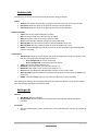
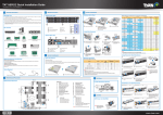
Front
1
2
3
4
5
TEMP
ANTENNA
RS232
CONSOLE
LAN
6
7
8
9
10
11
12
13
OUTPUT
OLED
UP
DOWN
MENU
OK
ALARM
POWER
N/A
N/A
4 x RS232 interface connector
Console connector
Ethernet connector + LED
Status LED is on = Ethernet connection established
Status LED is flashing = Ethernet activity on the network
Blue LED activity indicator for each of the 8 ports
OLED display
Move to the previous page or browse upwards in a selection list
Move to the next page or browse downwards in a selection list
Button to access menu function
Validation button
Red alarm LED indicator
Blue power LED indicator
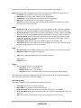
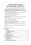
Rear
1
2
3
FUSE
INLET
OUTLET
4
5
AIRFLOW
TEMP
15A circuit breaker
16A inlet: IEC C20
8x outlet plug
Note: maximum load of 8A on each of the ports & 15A in total
N/A
N/A
© 2011 Racktivity Inc.
2100 Seaport Blvd., Suite 400, Redwood City 94063, USA – www.racktivity.com
6/25
v 2013.11.18
Installation
Mounting the PDU
1. The PDU comes with brackets for mounting in a rack.
•
•
Choose the appropriate location for the brackets on the sides of the unit (depending on the
desired deepness).
Attach the rack mounting brackets to the unit using 2 retaining screws, provided for each of the
brackets.
2. Attach the PDU to a vertical rail in your rack. Position the PDU, align the buttons with the
rack mounting slots and fix the PDU with the required screws (not inserted in the package).
3. When mounting the device, ensure that nothing is leaning on or close to the PDU. Best is to
leave open space for airflow and to assure accurate internal temperature measurements.
The PDU itself is a low power device with a power consumption of only 2 Watt.
Connecting the PDU
1. The PDU has a detachable power cord. Attach the included power cord to the device by
inserting the IEC C20 connector in to the IEC C20 inlet.
Note: Optionally, a user-supplied power cord can be attached to the PDU by connecting it to
the IEC inlet. Do not attempt to attach a user-supplied power cord unless it is certified to be
compatible with the input power source that will be used by the PDU.
2. Connect the input plug to a compatible AC power outlet.
Note: The AC power source should not share a circuit with a heavy electrical load.
3. Connect your equipment's input plugs to the outlet plugs of the PDU.
4. Only when the appropriate port status LED is lit does the PDU provide power to that port.
5. All blue port status LEDs will light up at first time use.
Note: When not first time use, it is possible that not all LEDs light up. The PDU will only activate
those ports that were active when power was shut down. Non-lit ports are not active.
© 2011 Racktivity Inc.
2100 Seaport Blvd., Suite 400, Redwood City 94063, USA – www.racktivity.com
7/25
v 2013.11.18
OLED Display
Activating the display
The OLED standby delay can be set at the Settings page on the Web Portal (the default value is 1
minute).
On the PDU, push any of the 4 buttons next to the OLED Display to activate the screen.
Using the display
The OLED is controlled using the UP, DOWN, MENU and OK buttons next to the screen.
Use the UP and DOWN buttons to navigate through the reporting screens or through a selection
list in the menus. Press OK to select the highlighted item and MENU to go back.
When in a menu, the ">" symbol indicates that clicking this item will open a submenu. The "●"
symbol indicates that this menu item leads directly to a setting.
Setting the brightness
1.
2.
3.
4.
Press the MENU button until the Main menu appears.
Select Brightness using the UP and DOWN buttons and press OK.
Use the UP and DOWN buttons to change the screen brightness.
Press MENU to save and exit.
Reporting Screens
Overview (1/7)
The Overview screen shows the total current in A (Ampère), the real power usage in Watts, the
temperature in degrees Celsius and the humidity in RH (Relative Humidity). These values are
updated in real time.
General (2/7)
This screen shows the current (in Ampère) for all 8 ports. A combined total is displayed on the
right (Tot Current), followed by the input voltage (in Volts) and frequency (in Hz). All values are
updated in real time. Ports shown in green are powered on, when shown in grey they are
powered off.
© 2011 Racktivity Inc.
2100 Seaport Blvd., Suite 400, Redwood City 94063, USA – www.racktivity.com
8/25
v 2013.11.18
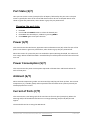
Port State (3/7)
Here you can see the current (in Ampère) for all 8 ports, followed by the port name. The port
name is typically the name of the connected device and can be set via the Web Portal. Ports
shown in green are powered on, when shown in grey they are powered off.
Changing the port state
1.
2.
3.
4.
Press OK
Use the UP and DOWN buttons to select the desired port.
Press OK at the selected port, validate by pressing MENU
Press MENU again to exit port selection.
Power (4/7)
This screen shows the Real Power, Apparent Power and Power Factor (PF) values for each of the
ports. Ports shown in green are powered on, when shown in grey they are powered off.
When the current of a particular port has reached the preset Warning threshold, the values will
turn orange. When the Off threshold is exceeded the port will be powered off and the values will
turn red.
Power Consumption (5/7)
This screen shows the power consumption expressed in kilowatt hour and kilovolt A hour for
each of the 8 ports.
Ambient (6/7)
When external temperature probes are connected (up to 8) they will show up here. The internal
temperature (°C), humidity (%RH) and an optional external airflow sensor (meters/second) are
also displayed on this screen.
Current of Ports (7/7)
This screen shows a real time graph of the used current for each port (in Ampère). When the
Warning and/or Off threshold have been set an orange (Warning) and/or red (Off) line will
appear.
The thresholds can be set using the Web Portal.
© 2011 Racktivity Inc.
2100 Seaport Blvd., Suite 400, Redwood City 94063, USA – www.racktivity.com
9/25
v 2013.11.18
TCP-IP Configuration
There are two methods for setting up the IP address: Dynamic IP Address assignment and
Manual IP Address assignment. If you are uncertain which method to use, contact your network
administrator for assistance before continuing the installation process.
Dynamic IP Address Assignment
Connect the PDU to a network. While the PDU is powered on, connect a standard Ethernet cable
to the RJ45 Ethernet port, the activity LED will light up to indicate Ethernet connectivity.
1. Press MENU until the Main menu appears, select Ethernet or Network using UP and DOWN
and press OK.
2. Within the Ethernet or Network menu, select DHCP (off) and press OK until DHCP (on)
appears.
3. Press MENU to return to the Main menu and use UP and DOWN to select Current IPAddress. The current IP-address is shown in yellow at the bottom of the OLED.
4. On a computer in the same network, use a browser to open the assigned IP-address, for
example http://192.168.14.250
5. When browsing to the Web Portal, a popup appears requesting a username and password.
The default values are:
Login: admin
Password: 1234
© 2011 Racktivity Inc.
2100 Seaport Blvd., Suite 400, Redwood City 94063, USA – www.racktivity.com
10/25
v 2013.11.18
Manual IP Address Assignment
Obtain the correct IP address, standard gateway, DNS Server IP and subnet mask from your
network administrator.
1. Press the MENU button until the Main menu appears, select Ethernet or Network using the
UP and DOWN buttons and press OK.
2. Within the Ethernet or Network menu, select DHCP (on) and press OK until DHCP (off)
appears.
3. Select SET IP-ADDRESS and press OK to change the settings (when navigating the menus, the
value for that setting is shown in yellow at the bottom of the OLED).
4. Use the UP and DOWN buttons to change the currently selected value and press OK to select
the next value. When holding the UP and DOWN buttons changing the values speeds up.
When ready press MENU to return to the Ethernet or Network menu.
5. Repeat the last 2 steps for the Subnet mask, Std Gateway and DNS Server settings.
6. On a computer in the same network, use a browser to open the chosen IP-address, for
example http://192.168.14.250
7. When browsing to the Web Portal, a popup appears requesting a username and password.
The default values are:
Login: admin
Password: 1234
© 2011 Racktivity Inc.
2100 Seaport Blvd., Suite 400, Redwood City 94063, USA – www.racktivity.com
11/25
v 2013.11.18
Using the Web Portal
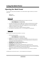
Opening the Web Portal
Use a browser to open the PDU IP address. You will be asked for login credentials, the default
values are:
Login: admin
Password: 1234
Status tab
•
•
•
•
The Status Screen shows the ON/OFF status of the 8 ports on the PDU
o Grey background: port is powered OFF
o Green background: port is powered ON
The button underneath each port toggles the port status instantly (even when a delay
has been set on the Protection tab). The load is activated at the zero crossing of the
voltage to avoid interference on the voltage. Toggling a port state always triggers an
SNMP Trap, regardless of other settings.
For each port, the real time True RMS is displayed (in Ampère)
The default port names (port1, port2,...) can be changed at the Settings tab.
Power tab
This tab shows all the power measurements in real time.
•
•
•
•
•
•
•
•
•
•
Port: Port name and status
o Grey background: Port is powered OFF
o Green background: Port is powered ON
Current: The real time current is displayed (in Ampère)
Maximum: The maximum current measured (in Ampère). Hover your mouse over this
value to see a timestamp that indicates when the maximum value was measured. This
value can be reset at the Protection tab
Real Power: The real power usage (in Watts)
Apparent Power: The apparent power (in Volt Ampère)
Power Factor: The power factor (in %)
Resettable kWh: The total amount of kilowatt hours since the last reset
Resettable kVAh: Total apparent power (in kilo Volt Ampère hours) since the last reset
Reset: Resets the Resettable kWh and the Resettable kVAh (note: this reset will not clear
the maximum column, this can be done at the Protection tab)
kWh: The total kilowatt hours since the PDU has been in use. This value can NOT be
reset.
The default port names (port1, port2,...) can be changed at the Settings tab.
© 2011 Racktivity Inc.
2100 Seaport Blvd., Suite 400, Redwood City 94063, USA – www.racktivity.com
12/25
v 2013.11.18
Ambient tab
The Ambient tab shows the environmental parameters being measured.
Sensor
• Airflow: The airflow measured by an optional external sensor (in meters per second)
• Intrusion1: Shows the state of an optional external intrusion detector
• Intrusion2: Shows the state of an optional external intrusion detector
Relative Humidity
• Value: The current relative humidity (in %RH)
• Min: The lowest value since the last reset (in %RH)
• Max: The highest value since the last reset (in %RH)
• Reset: resets the Min and Max columns to the current value
• Warning Min: Sets the minimum value at which an SNMP trap is sent
• Warning Max: Sets the maximum value at which an SNMP trap is sent
• SNMP: if checked SNMP traps will be sent when the Warning Min and/or Warning Max
values are crossed.
Temperature
• Temperature: Shows the state of both the internal temperature sensor (on the first row)
and any connected optional temperature sensors
o Grey background: No sensor connected
o Green background: Connected and active sensor
• Value: The current temperature (in °C)
• Minimum: The lowest value since the last reset (in °C)
• Maximum: The highest value since the last reset (in °C)
• Reset: Resets the Minimum and Maximum columns to the current value
• Warning Level: Sets the maximum temperature that when crossed causes an SNMP trap
to be sent
• SNMP: If checked SNMP traps are sent when the Warning Level is exceeded
After editing the settings on the Ambient tab, press the Save Data button. A pop-up will appear
after the changes have been successfully saved.
Settings tab
General
• PDU Name: Name of the PDU
• Rack Position: Optional administrative parameter that indicates where the PDU is
installed.
Port Name
• Sets the preferred port names, typically the internal identification used for the connected
devices
© 2011 Racktivity Inc.
2100 Seaport Blvd., Suite 400, Redwood City 94063, USA – www.racktivity.com
13/25
v 2013.11.18
The following settings are only available when the DHCP checkbox is unchecked:
Ethernet (Warning: when changing these values connection to the Web Portal might be lost)
• IP-Address: The IP-address used for TCP/IP configuration
• Subnetmask: The subnet mask used for TCP/IP configuration
• Std Gateway: The standard gateway used for TCP/IP configuration
• DNS-server: The DNS-server used for TCP/IP configuration
• DHCP: When checked the PDU will automatically be assigned an IP-address (if a DHCP
server is present on the network)
SNMP
• Community read: Sets the community read string, default: "public". When using SNMP
software on a pc to collect SNMP data (GET command) this string is used as verification
• Community write: Sets the community write string, default: "private". When using SNMP
software on a pc to change SNMP data (SET command) this string is used as verification
• Write protection: When checked this setting will prevent changes being made through
SNMP (SET command), even when using the correct Community write string. It can be
used as an additional protection
• Trap receiver port: Sets the port for the SNMP Trap function, default: "162"
• Trap receiver IP: Sets the IP address where the SNMP Trap is sent, this is normally the IP
of a monitoring computer on the same network
OLED
•
•
•
Min. before Off: Sets the OLED standby delay when no buttons are pressed (in minutes)
Brightness [2-10]: Sets the OLED's brightness
Login: Sets a new login and password. The default values are:
Login: admin
Password: 1234
Logging
• Sets the logging values for the Logging tab
o Short term: From 1 - 255 seconds
o Medium term: From 1 - 255 minutes
o Long term: From 2 - 255 medium term intervals (specified in the above setting)
After editing the settings on the Settings tab, press the Save Data button. A pop-up will appear
after the changes have been successfully saved.
Time Settings (UTC)
The following settings are only available when NTP is unchecked
•
•
•
•
•
Time (HM): Sets the time (in hours:minutes)
Date (DMY): Sets the date (in days/months/years)
Local NTP-server: NTP server IP when Use Default NTP Server is not checked
Use Default NTP server: When checked the PDU will connect to pool.ntp.org for the time
settings
NTP: When checked the PDU will try to get time settings from an NTP server
© 2011 Racktivity Inc.
2100 Seaport Blvd., Suite 400, Redwood City 94063, USA – www.racktivity.com
14/25
v 2013.11.18
Protection tab
Use this tab to set the thresholds and alarms that provide disaster prevention and other recovery
functions for each port.
•
•
•
Port: Port name and status
Grey background: Port is powered OFF
Green background: Port is powered ON
•
•
•
Current: Real time current in milliampère
Maximum: Maximum current in milliampère since the last reset
Reset: Resets the Maximum value. Hover your mouse over this value to see a timestamp
that indicates when the maximum value was measured.
Warning Level: When this threshold (in milliampère) is exceeded an SNMP Trap is sent (if
the SNMP checkbox for this port is checked)
Off Level: when this threshold (in milliampère) is exceeded the port is automatically
powered off and an SNMP trap is sent (if the SNMP checkbox for this port is checked)
Temp Off: When this temperature threshold (in °C) is exceeded by the internal
temperature sensor the port is automatically powered off and an SNMP trap is sent (if
the SNMP checkbox for this port is checked)
SNMP: When checked SNMP Traps are enabled for this port
Priority
o The PDU looks at the thresholds of each port before checking the SUM. So, if a port
exceeds its Off Level threshold that port is powered off, followed by a check of the
"SUM" Off Level threshold.
o When the Off threshold in the "SUM" row is exceeded, the device looks at the
individual port priority settings to determine which port to power down first,
second,... even when it wasn't that port that caused the threshold to be exceeded. A
lower number means a higher priority (1 is the highest priority, 8 the lowest).
o If 2 ports have the same priority level, the PDU will determine which port had the
highest current increase and will power off that port. If no current increase is found,
the port that was powered on last is powered off.
Delay On: sets the startup delay (in seconds) after the PDU has been powered off and
back on (Toggling a port's state manually ignores this setting).
•
•
•
•
•
Voltage table
• Value: Current voltage measured
• Warning Min: When the measured voltage goes below this threshold an SNMP trap is
sent (with SNMP checked)
• Warning Max: When the measured voltage exceeds this threshold an SNMP trap is sent
(with SNMP checked)
• SNMP: When checked, SNMP traps are sent when the measured voltage is below the
minimum or above the maximum threshold
After editing the settings on the Protection tab, press the Save Data button. A pop-up will appear
after the changes have been successfully saved.
© 2011 Racktivity Inc.
2100 Seaport Blvd., Suite 400, Redwood City 94063, USA – www.racktivity.com
15/25
v 2013.11.18
Serial tab
The settings for the PDU's 4 serial connectors can be changed on this tab.
•
•
•
•
Port: The number of the serial connector as seen on the front of the PDU
Baudrate: Possible baudrates for serial communication. The baudrate of the serial
connector and a connected device must be the same
TelnetPort: Sets the telnet port. The port must end in the same number as the
corresponding serial connector (serial connector 3 cannot have a port ending with 4 (ie:
30004), it must end with a 3 (ie: 14203)
Reset Telnet: Disconnects an active telnet session. This button does not alter any other
settings.
After editing the settings on the Serial tab, press the Save Data button. A pop-up will appear after
the changes have been successfully saved.
Schedule tab
Here you can specify a schedule which defines for each port if and when it should be turned off
and/or on and if this should be repeated on a daily basis.
•
•
•
•
•
•
Port: Port name and status
o Grey background: Port is powered OFF
o Green background: Port is powered ON
Time Off: Time in hours:minutes when the port is to be turned off (with Off Enable
checked)
Off Enable: When checked the port will be turned off at the time specified in Time Off
Time On: Time in hours:minutes when the port is to be turned on (with On Enable
checked)
On Enable: When checked the port will be turned on at the time specified in Time on
Repeat Daily: When checked the specified schedule for that port will be repeated daily
The current time is displayed below the table.
After editing the settings on the Schedule tab, press the Save Data button. A pop-up will appear
after the changes have been successfully saved.
Logging tab
The PDU’s short- medium- long- and event logging are displayed on this tab. For each type the
number of items needed can be specified. Changing the logging intervals can be done at the
Settings tab.
© 2011 Racktivity Inc.
2100 Seaport Blvd., Suite 400, Redwood City 94063, USA – www.racktivity.com
16/25
v 2013.11.18
SNMP Configuration
SNMP (Simple Network Management Protocol) is mostly used in network management systems
to monitor network-attached devices for conditions that warrant administrative attention.
The PDU features both access to SNMP data and the ability to send SNMP Traps.
Configuring SNMP
•
Make sure that the PDU has been properly configured for use on the network.
•
Use a browser to open the PDU's IP address. You will be asked for login credentials, the
default values are:
Login: admin
Password: 1234
•
•
Go to the Settings tab
Under the SNMP section you will find the following:
o Community read: Sets the community read string, default: "public". When using SNMP
software on a pc to collect SNMP data (GET command) this string is used as verification
o Community write: Sets the community write string, default: "private". When using SNMP
software on a pc to change SNMP data (SET command) this string is used as verification
o Write protection: When checked this setting will prevent changes being made through
SNMP (SET command), even when using the correct Community write string. It can be
used as an additional protection
o Trap receiver port: Sets the port for the SNMP Trap function, default: "162"
o Trap receiver IP: Sets the IP address where the SNMP Trap is sent, this is normally the IP
of a monitoring computer on the same network
SNMP Usage
Monitoring software with SNMP functionality enables you to stay on top of any developments
concerning the PDU. All relevant data (measurements, settings, port states, thresholds,...) are
accessible through SNMP GET requests.
Make sure to load the Racktivity MIB file (found here) to get the full benefits of SNMP
monitoring. Software like iReasoning's MIB Browser can help get results quickly, while Zenoss
monitoring software takes a more in depth approach.
© 2011 Racktivity Inc.
2100 Seaport Blvd., Suite 400, Redwood City 94063, USA – www.racktivity.com
17/25
v 2013.11.18
Serial Configuration
The PDU has 4 serial RS232 connectors located at the front to connect upto 4 external devices,
ie: switches, servers,...
These connectors are primarily for recovery purposes, so when you have been locked out of an
external device you can still connect to it through Telnet using the PDU's ethernet connection.
Configuring the serial connectors
•
•
Make sure that the PDU has been properly configured for use on the network. For more info
see TCP-IP Configuration
Use a browser to open the PDU's IP address. You will be asked for login credentials, the
default values are:
Login: admin
Password: 1234
•
Go to the Serial tab
Here you can specify for each connector:
• Port: The number of the serial connector as seen on the front of the PDU
• Baudrate: Possible baudrates for serial communication. The baudrate of the serial
connector and a connected device must be the same
• TelnetPort: Sets the telnet port. The port must end in the same number as the
corresponding serial connector (serial connector 3 cannot have a port ending with 4 (ie:
30004), it must end with a 3 (ie: 14203)
• Reset Telnet: Disconnects an active telnet session. This button does not alter any other
settings.
Using the Serial Connectors
•
•
•
•
Make sure the PDU and your computer are connected to the same subnet on the same
network.
Connect a serial cable between one of the PDU's configured serial connectors and an
external device's serial port. The used Baudrates on both devices should be the same
Start a Telnet session at the PDU's IP and with the correct port.
You will be asked for login credentials, the default values are:
Login: admin
Password: 1234
•
You are now connected, please refer to the external device's documentation for more
information on the serial connection options.
© 2011 Racktivity Inc.
2100 Seaport Blvd., Suite 400, Redwood City 94063, USA – www.racktivity.com
18/25
v 2013.11.18
Use Case
Requirements
•
•
•
•
A fully configured PDU with an active ethernet connection
A PC with Putty software (download it here) and an active ethernet connection
Device with a console port (ie: a Cisco switch)
A female DB9 to console cable
How to
•
•
•
•
•
•
Install Putty
Connect the cable between the PDU's 1st RS232 port and the device's console port
Make sure the PDU and PC are on the same subnet and are switched on
Open Putty and enter the following:
o Connection Type: Telnet
o Host name: the PDU's IP address (ie: 192.168.14.250)
o Port: the default port for RS232 connector 1 is 2001 (can be changed at the Web Portal's
Serial page)
Press "Open"
You will be asked for login credentials, the default values are:
Login: admin
Password: 1234
•
Many devices require that you press the Enter key a few times before anything can be seen.
You are now connected to the device's console port through ethernet. Up to 4 devices can be
connected to the PDU's RS232 connectors.
SNMP MIB Files
Download the MIB files appropriate to your firmware from the Support section
© 2011 Racktivity Inc.
2100 Seaport Blvd., Suite 400, Redwood City 94063, USA – www.racktivity.com
19/25
v 2013.11.18
Specifications
Devices Connectable
Supported Voltages
RS232 ports
Networking
SNMP Monitoring, alerting and management
Remote control software
Integrated Remote Control Web server
Max current per port
Max current per PDU
Enable/Disable ports
Form factor
Color graphical OLED Display
LED Indicators
Rack Mountable
Power consumption
Steel Case
Control buttons on front
Automatic Fuse Hardware 15 Ampère
Microcontrolled based Fuse on each port
Internal Temperature
© 2011 Racktivity Inc.
2100 Seaport Blvd., Suite 400, Redwood City 94063, USA – www.racktivity.com
8
110/220V
4
Ethernet
Yes
Yes
Yes
8A
15A
Yes
1U
Yes
Yes
Yes
4 watt
Yes
Yes
Yes
Yes
Yes
20/25
v 2013.11.18
PDU Family Warranty
Warranty and Limitation of Liability
Racktivity agrees to repair or replace Datacenter Management Units ("Products") that fail due to
a defect within twenty four (24) months after the shipment date of each Product unit to Buyer
("Warranty Period"). For purposes of this Agreement the term "defect" shall mean the Product
fails to operate or fails to conform to its applicable specifications. Any claim made pursuant to
this Agreement shall be asserted or made in writing only by Buyer. Buyer shall comply with
Racktivity's Standard Return Merchandise Authorization ("RMA") procedure for all warranty
claims as set forth in Racktivity's operation manual. Buyer must return Products in original
packaging and in good condition. This limited warranty does not include labor, transportation, or
other expenses to repair or reinstall warranted Products on site or at Buyer's premises. The
warranty only applies to the original Buyer.
Racktivity reserves the right to investigate any warranty claims to promptly resolve the problem
or to determine whether such claims are proper. In the event that after repeated efforts
Racktivity is unable to repair or replace a defective Product, then Buyer's exclusive remedy and
Racktivity's entire liability in contract, tort, or otherwise shall be the payment by Racktivity of
Buyer's actual damages after mitigation, but shall not exceed the purchase price actually paid by
Buyer for the defective Product.
Racktivity shall have no responsibility or liability for any Product, or part thereof, that (a) has had
the Serial Number, Model Number, or other identification markings altered, removed or
rendered illegible; (b) has been damaged by or subject to improper installation or operation,
misuse, accident, neglect and/or has been used in any way other than in strict compliance with
Racktivity's operation and installation manual; (c) has become defective or inoperative due to its
integration or assembly with any equipment or products not supplied by Racktivity; (d) has been
repaired, modified or otherwise altered by anyone other than Racktivity and/or has been subject
to the opening of any sealed boxes without Racktivity's prior written consent. If any warranty
claim by Buyer falls within any of the foregoing exceptions, Buyer shall pay Racktivity its then
current rates and charges for such services.
THE ABOVE WARRANTY IS IN LIEU OF ALL OTHER WARRANTIES, EXPRESS OR IMPLIED, INCLUDING
THOSE OF MERCHANTABILITY AND FITNESS FOR A PARTICULAR PURPOSE, ALL OF WHICH ARE
EXPRESSLY DISCLAIMED. RACKTIVITY SHALL NOT BE LIABLE FOR ANY CONSEQUENTIAL,
INCIDENTAL, SPECIAL, OR EXEMPLARY DAMAGES; EVEN OF IT HAS BEEN ADVISED OF THE
POSSIBILITY OF SUCH DAMAGES.
For warranty issues, contact the Product Support Department. All repair and return shipments
must be approved by Racktivity and must be accompanied by a RMA (Return Merchandise
Authorization) number and dated proof of purchase.
© 2011 Racktivity Inc.
2100 Seaport Blvd., Suite 400, Redwood City 94063, USA – www.racktivity.com
21/25
v 2013.11.18
Troubleshooting
Password Reset
Resetting the password can be done on the device itself:
•
•
Press and hold the UP and DOWN buttons simultaneously for 4 seconds.
The password will now be reset to the factory default settings:
Login: admin
Password: 1234
This reset only affects the login credentials, no other settings are changed.
Factory Reset
If you would like to reset the PDU to the factory default settings this can be done on the device
itself:
WARNING! This will completely erase all settings, and could power down all ports. Make sure no
vital equipment is connected to the PDU when performing a Factory Reset.
•
•
Press and hold the MENU and OK buttons simultaneously for 4 seconds.
The device is now completely erased of user specified settings, the default login values are:
Login: admin
Password: 1234
Determine Your Firmware
Web Portal
Open the Web Portal on the PDU. The firmware version is displayed in the top right corner after
you log in (next to "SW V" + your firmware version).
OLED Display
On the PDU open the Main menu, then select Version Numbers followed by Software Version.
The firmware version is displayed at the bottom of the OLED in yellow.
© 2011 Racktivity Inc.
2100 Seaport Blvd., Suite 400, Redwood City 94063, USA – www.racktivity.com
22/25
v 2013.11.18
Determine Your IP Address
To determine the IP address currently used by the PDU, first choose your firmware version:
1. Press MENU until the Main menu appears, select Network or Ethernet using UP and DOWN
and press OK.
2. Use UP and DOWN to select Current IP-Address. The current IP-address is shown in yellow at
the bottom of the OLED
Firmware Update
To obtain the necessary software to update your PDU's firmware, please contact Racktivity
Support.
1.
2.
3.
4.
5.
6.
7.
Make sure that your computer and the PDU are on the same network and fully functional
Unpack the update package
Open the software tool "Racktivity Ethernet Bootloader.exe"
Use the "File" button to select the .cry file that came with the update package
Fill in the appropriate IP address and login credentials of the designated PDU
Press "Update firmware" to start the update
The update has successfully completed when "Programming completed / Exit bootloader" is
shown (the update takes a few minutes)
Latest version
The latest available firmware version for the PM0816-01 is v1.01.
© 2011 Racktivity Inc.
2100 Seaport Blvd., Suite 400, Redwood City 94063, USA – www.racktivity.com
23/25
v 2013.11.18
Troubleshooting
After starting the update "FAILED (check Settings)" is shown.
Please make sure that:
• The PDU is powered on and connected to LAN with a correct IP address
• You entered the correct login credentials under "Settings" in the software tool
• You are on the same LAN as the PDU
To verify the above settings are correct, go to the Web Portal and log in.
The Status window continuously shows output similar to
"**ERROR Out of Sequence PDU Seq: 5294 5299".
•
This is a mere warning and does not compromise the update.
The update fails and the PDU becomes unresponsive.
•
•
If needed: restore power and/or Ethernet to the PDU
Repeat the steps above to start the update again
In case you need to know the IP address, and it cannot be retrieved using the regular methods
then:
•
•
•
•
Connect a console cable between the PDU and your pc.
Use the following settings to read the output: Baudrate 38400, 8 databits, no parity, 1
stopbit.
Reboot the PDU, the currently used IP address is shown in the console output.
Repeat the steps above to start the update again.
© 2011 Racktivity Inc.
2100 Seaport Blvd., Suite 400, Redwood City 94063, USA – www.racktivity.com
24/25
v 2013.11.18
Support
Feel free to contact us if you need any support or have any other questions or remarks:
Online
www.racktivity.com/support
E-mail
[email protected]
Phone
003293242095 (GMT+1)
© 2011 Racktivity Inc.
2100 Seaport Blvd., Suite 400, Redwood City 94063, USA – www.racktivity.com
25/25
v 2013.11.18