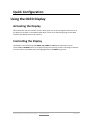
1
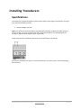
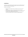
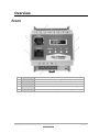
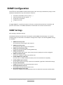
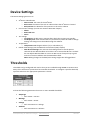
User Manual 2 AC Sensor Contents Contents .................................................................................................................................................. 2 Introduction............................................................................................................................................. 4 Features ............................................................................................................................................... 4 Applicable Models ............................................................................................................................... 5 Specifications....................................................................................................................................... 5 Electrical Ratings ............................................................................................................................. 5 Operating Environment ................................................................................................................... 5 Dimensions ...................................................................................................................................... 5 User Account Overview ................................................................................................................... 6 Safety ................................................................................................................................................... 7 Certifications ................................................................................................................................... 8 Compliance ...................................................................................................................................... 8 Recycling .............................................................................................................................................. 9 Servicing & Repair ............................................................................................................................... 9 Additional Documentation .................................................................................................................. 9 Getting Started .................................................................................................................................. 10 Receiving Inspection ...................................................................................................................... 10 Inventory ....................................................................................................................................... 10 Installation ............................................................................................................................................. 11 Mounting the AC2Sensor ................................................................................................................... 11 Connecting the AC2Sensor ................................................................................................................. 11 Installing Transducers........................................................................................................................ 12 Specifications ................................................................................................................................. 12 Installation ..................................................................................................................................... 13 Overview................................................................................................................................................ 14 Front .................................................................................................................................................. 14 Status LEDs ........................................................................................................................................ 15 Power LEDs (1)............................................................................................................................... 15 Quick Configuration............................................................................................................................... 16 Using the OLED Display ..................................................................................................................... 16 Activating the Display .................................................................................................................... 16 Controlling the Display .................................................................................................................. 16 Network Settings ............................................................................................................................... 17 Dynamic IP Address Assignment (DEFAULT) ................................................................................. 17 Manual IP Address Assignment ..................................................................................................... 18 Web Interface ........................................................................................................................................ 19 © 2011 Racktivity NV Antwerpsesteenweg 19 - 9080 Lochristi - Belgium - www.racktivity.com 2/32 v 2013.5.23 Getting Started .................................................................................................................................. 19 Supported Web Browsers ............................................................................................................. 19 Logging in....................................................................................................................................... 19 Layout ................................................................................................................................................ 20 Tabs ................................................................................................................................................... 21 Power............................................................................................................................................. 21 Environment .................................................................................................................................. 21 Logging .......................................................................................................................................... 21 Modules ......................................................................................................................................... 21 Management ................................................................................................................................. 21 Settings .......................................................................................................................................... 22 Network Configuration .................................................................................................................. 22 SNMP Configuration .......................................................................................................................... 23 SNMP Settings ............................................................................................................................... 23 Device Settings .................................................................................................................................. 24 Thresholds ......................................................................................................................................... 24 Resetting Measurements .................................................................................................................. 26 Network Time Protocol (NTP) ........................................................................................................... 26 CLI .......................................................................................................................................................... 27 Introduction....................................................................................................................................... 27 Connecting......................................................................................................................................... 27 Logging .................................................................................................................................................. 28 Event .................................................................................................................................................. 28 Management Information Base (MIB) .................................................................................................. 29 Upgrade Firmware................................................................................................................................. 30 Obtaining Files ................................................................................................................................... 30 Troubleshooting .................................................................................................................................... 31 Resetting Login Credentials ............................................................................................................... 31 Connecting to the Web Interface ...................................................................................................... 31 Knowing your AC2Sensor’ IP address................................................................................................. 31 Support .................................................................................................................................................. 32 © 2011 Racktivity NV Antwerpsesteenweg 19 - 9080 Lochristi - Belgium - www.racktivity.com 3/32 v 2013.5.23 Introduction Features The AC2Sensor, Racktivity’s newest addition to its data center power monitoring and management solution can be installed at the AC power distribution board or in distributed remote locations such as PoPs, base stations, and head ends. The unit features a DIN rail mountable design and Ethernet connectivity and supports 8 inputs for current measurements. Main Features: Measure AC voltage o On 3 phases: L1, L2, L3 o Input range: 100-240 VAC o Accuracy: +/- 2% Measure AC current o On 8 inputs: each input can be manually assigned to the corresponding phase o Input range: up to 1500A (depends on the current transducer used) o Accuracy: +/- 2% Calculates power (W) and power consumption (kWh) per input Power supply via L1 (phase 1) Input grouping (3 phases) and neutral current calculation © 2011 Racktivity NV Antwerpsesteenweg 19 - 9080 Lochristi - Belgium - www.racktivity.com 4/32 v 2013.5.23 Applicable Models Unless specified otherwise, all information in this document is applicable to the following Racktivity AC2Sensor model(s): ACS08-03 Specifications Electrical Ratings Input: Voltage 100-240 VAC Operating Environment Operating temperature Storage temperature Humidity 0°C to 50°C -10°C to 60°C 5% to 85% RH 32°F to 122°F 14°F to 140°F non-condensing Dimensions Dimensions cm (WxHxD) Dimensions inch (WxHxD) 7.1 x 9 x 5.3 2.8 x 3.54 x 2.1 © 2011 Racktivity NV Antwerpsesteenweg 19 - 9080 Lochristi - Belgium - www.racktivity.com 5/32 v 2013.5.23 User Account Overview The AC2Sensor has 3 types (levels) of user accounts: admin, restricted and guest. The following table shows an overview of the functionalities of each type: Open website Open CLI session View current status (states, data & values) Edit thresholds Edit port names Change SNMP notification settings Edit device settings View & download logs Default user name Default password admin Yes Yes Yes Yes Yes Yes Yes Yes admin 1234 restricted Yes Yes Yes No No No No No restricted 1234 guest Yes Yes Yes No No No No No guest 1234 The same features and options apply to both the website and the Command Line Interface (CLI). To change the login credentials for the users please refer to the Device Settings chapter. © 2011 Racktivity NV Antwerpsesteenweg 19 - 9080 Lochristi - Belgium - www.racktivity.com 6/32 v 2013.5.23 Safety Save these instructions! This Safety Information contains important instructions that should be followed during installation and maintenance of the AC2Sensor. It is intended for Racktivity customers who set up, install, relocate or maintain Racktivity equipment. Changes and modifications to this unit not specifically approved by Racktivity could void the warranty. Electrical Hazard! Read the following information before installing or operating your AC2Sensor: Do not work alone under hazardous conditions. High current through conductive materials could cause severe burns. Follow all local and national codes when installing the AC2Sensor. To avoid possible electrical shock and equipment damage, use only the supplied hardware. The power connector serves as connection switch for the AC2Sensor. Do not operate your AC2Sensor with any covers removed or when damaged. There are no user serviceable parts inside the AC2Sensor. All repairs and service should be performed by authorized service personnel only. The AC2Sensor is designed for indoor use only in a controlled environment away from excess moisture, temperature extremes, conductive contaminants, dust, direct sunlight or magnetic sources. Do not attempt to mount the AC2Sensor to an insecure or unstable surface. Never attempt to install electrical equipment during a thunderstorm. Use of this equipment in life support applications or any medical applications is strictly prohibited since failure of this equipment can reasonably be expected to cause the failure of the life support equipment or to significantly affect its safety. CAUTION: The AC2Sensor contains a lithium battery and should not be disposed of with general refuge. Dispose of the lithium battery in accordance with all local codes and regulations for products containing lithium batteries. Contact your local environmental control or disposal agency for further details. The battery is not intended to be user replaceable. © 2011 Racktivity NV Antwerpsesteenweg 19 - 9080 Lochristi - Belgium - www.racktivity.com 7/32 v 2013.5.23 Certifications Not all certifications are applicable to every model. Please check the label on your device. CE / FCC This device is designed in compliance with the requirements of the 4 following regulations: EN 55022: Class B EN 61000-3-2 EN 6100-3-3 EN 55024 This device is certified to comply with Part 15 of the FCC rules. Compliance WEEE Waste Electrical and Electronic Equipment RoHS Restriction of Hazardous Substances © 2011 Racktivity NV Antwerpsesteenweg 19 - 9080 Lochristi - Belgium - www.racktivity.com 8/32 v 2013.5.23 Recycling The materials used for shipping the AC2Sensor are recyclable, please save them for later use or dispose of them appropriately. Servicing & Repair There are no user serviceable parts inside the AC2Sensor. All repairs and service should be performed by authorized service personnel only. Please refer to the Service manual for RMA procedure. Additional Documentation Additional documentation and support regarding the following subjects is available on the Racktivity website http://www.racktivity.com/support/. API o Manual o GUID Overview o (python) Examples 2 E Sensor User Manual Servicing (RMA) © 2011 Racktivity NV Antwerpsesteenweg 19 - 9080 Lochristi - Belgium - www.racktivity.com 9/32 v 2013.5.23 Getting Started Receiving Inspection Inspect the package (see INVENTORY section) and contents for shipping damage and make sure that all parts were received. Report any damage immediately to the shipping agent and report missing contents, damage, or other problems immediately to your reseller. Inventory Please verify the contents of the box: Standard Package Item AC2Sensor Connector Quantity 1 1 © 2011 Racktivity NV Antwerpsesteenweg 19 - 9080 Lochristi - Belgium - www.racktivity.com 10/32 v 2013.5.23 Installation Mounting the AC2Sensor Mount the AC2Sensor to a horizontal DIN rail using the slots at the back of the unit. Hold the unit with the top (white) slider over the DIN rail and while slightly pulling the unit down, place the bottom (black) slider over the bottom of the DIN rail. To remove the AC2Sensor use a flathead screwdriver to slightly pull the bottom (black) slider down. This will enable you to pull the bottom of the unit forward and release it from the DIN rail. Connecting the AC2Sensor 1. The AC2Sensor is powered from the L1 connector. 2. Attach the supplied connector to an existing 100-240 VAC power cable by using the screws. 3. The POWER LED (blue) adjacent to the connected connector will become active. © 2011 Racktivity NV Antwerpsesteenweg 19 - 9080 Lochristi - Belgium - www.racktivity.com 11/32 v 2013.5.23 Installing Transducers Specifications The AC2Sensor has been designed to communicate with a wide range of transducers as long as they meet the following criteria: Output voltage: -4V/+4V Note: The AC2Sensor features fixed list of predefined transducer models with wide variety of current ranges. If you are uncertain that your preferred transducer is compatible with the AC2Sensor, please contact Support prior to purchase. The pin layout of the transducer connectors on the AC2Sensor is as follows: Connect the transducer for input 1 into C1 and C2 holes. For other inputs, use corresponding pairs of holes. © 2011 Racktivity NV Antwerpsesteenweg 19 - 9080 Lochristi - Belgium - www.racktivity.com 12/32 v 2013.5.23 Installation The AC2Sensor can be installed and operated by connecting only 1 of the available phases (it has to be L1) in the connector. If certain metrics are missing for a specific transducer, please verify that there is an active phase for that transducer. To install a current transducer: Connect the current transducer cable to an available 2 pins in the connector on the AC2Sensor. Connect the current transducer to the power cable that needs to be monitored. Using web interface, in “Settings” > “Sensor Settings” set the correct transducer type and phase (you can use the suggested detected phase setup) The AC2Sensor display and web portal will now show the correct current values (and power values if the phase connector for that phase is attached and powered). © 2011 Racktivity NV Antwerpsesteenweg 19 - 9080 Lochristi - Belgium - www.racktivity.com 13/32 v 2013.5.23 Overview Front 1 2 3 4 5 6 CONN POWER LAN R BUS OLED NAV BUTTONS Transducer connectors 1 to 8 Input voltage connector with power LED Ethernet connector (with connectivity indicator LEDs) RS485 peripheral bus connector (for external modules) Measurements and settings OLED Menu, Up, Down and OK navigation buttons © 2011 Racktivity NV Antwerpsesteenweg 19 - 9080 Lochristi - Belgium - www.racktivity.com 14/32 v 2013.5.23 Status LEDs Power LEDs (1) ON OFF © 2011 Racktivity NV Antwerpsesteenweg 19 - 9080 Lochristi - Belgium - www.racktivity.com The device is powered No power is provided to the device 15/32 v 2013.5.23 Quick Configuration Using the OLED Display Activating the Display When the Power LED is lit and the screen is black, push any of the 4 navigation buttons next to the display to activate it. The OLED standby delay can be set at the Settings page on the Web Interface (the default value is 10 minutes). Controlling the Display The display is controlled using the MENU, UP, DOWN and OK buttons below the screen. Use the UP and DOWN buttons to navigate through the reporting screens or through a selection list in the menu. Press OK to select the highlighted item and MENU to go back. © 2011 Racktivity NV Antwerpsesteenweg 19 - 9080 Lochristi - Belgium - www.racktivity.com 16/32 v 2013.5.23 Network Settings There are two methods for setting up the IP address: Dynamic IP address assignment and Manual Assignment. If you are uncertain which method to use, contact your network administrator for assistance before continuing the installation process. Note: The AC2Sensor has secure HTTP (HTTPS) enabled by default. Use ‘https://’ instead of ‘http://’ in your browser to access the web portal. Dynamic IP Address Assignment (DEFAULT) 1. Press the MENU button until the MENU appears, select Network Settings using the DOWN button and press OK. 2. Within the Network Settings menu, select DHCP and press OK. When the value DHCP: ON is displayed, the device already has dynamic IP assignment enabled (skip to step 4). If not, use the UP or DOWN buttons to change the value to ‘DHCP: OFF’ and afterwards press MENU or OK to confirm. 3. Use the UP button to select Apply Settings and press OK. Press the MENU button to cancel or the OK button to apply the settings. 4. Press DOWN to select IP Address and press OK to display the current IP address. 5. On a computer in the same network, use a browser to open the assigned IP address, for example https://192.168.14.250 6. When surfing to the web portal, a login screen appears. The default user name is admin and the default password is 1234. © 2011 Racktivity NV Antwerpsesteenweg 19 - 9080 Lochristi - Belgium - www.racktivity.com 17/32 v 2013.5.23 Manual IP Address Assignment 1. Obtain the correct IP address, standard gateway, DNS Server IP and subnet mask from your network administrator. 2. Press the MENU button until the MENU appears, select Network Settings using the DOWN button and press OK. 3. Within the Network Settings menu, select DHCP and press OK. When the value ‘DHCP: OFF’ is displayed, the device already has manual IP assignment enabled. If not, use the UP or DOWN buttons to change the value to ‘DHCP: OFF’ and press MENU or OK to confirm. 4. Use the UP button to select IP Address and press OK. 5. Use the UP and DOWN buttons to change the currently selected value and press OK to select the next value. When holding the UP and DOWN buttons, you can speed up the changing of the values. When ready press MENU to confirm and return to the Network Settings menu. 6. Repeat the last two steps for the Subnet Mask, Standard Gateway and DNS Server settings. 7. Use the UP button to select Apply Settings and press OK. Press the MENU button to cancel or the OK button to apply the settings. 8. On a computer in the same network, use a browser to open the chosen IP address, for example https://192.168.14.250 9. When surfing to the web portal, a popup appears requesting a username and password. The default username is admin and the default password is 1234 © 2011 Racktivity NV Antwerpsesteenweg 19 - 9080 Lochristi - Belgium - www.racktivity.com 18/32 v 2013.5.23 Web Interface Getting Started Supported Web Browsers The following browsers have been tested and certified to work with the AC2Sensor Web Interface (on all platforms): Internet Explorer 8 or higher Firefox 3.6.16 or higher Chrome 11.0.696.71 or higher Opera 11.11 or higher Safari 5.0.5 Other available web browsers may work with the AC2Sensor but have not been fully tested by Racktivity. Logging in For instructions on how to set up the TCP/IP settings to connect to the Web Interface, please see the Network Settings chapter. To recover from a lost password, please refer to the Troubleshooting chapter. Use an internet browser to open the AC2Sensor IP address. You will be asked for login credentials, the default values for the administrator account are: User name Password Admin 1234 To find out everything about the different types of user accounts see the User Account Overview chapter. It is possible that you get a warning about the connection being untrusted (self-signed certificate. If so, please ignore. © 2011 Racktivity NV Antwerpsesteenweg 19 - 9080 Lochristi - Belgium - www.racktivity.com 19/32 v 2013.5.23 Layout 1 2 3 4 Sub tabs User account Main tabs Device info 5 6 Transducers Device time Displays the different sections of the selected main tab Displays which type of User Account is currently logged in Displays the different functions of the AC2Sensor Displays the device name, cabinet name & cabinet location Can be changed at the settings tab Displays the available info for each transducer of 8 inputs The time set on the Settings tab (either manual or through an NTP server) © 2011 Racktivity NV Antwerpsesteenweg 19 - 9080 Lochristi - Belgium - www.racktivity.com 20/32 v 2013.5.23 Tabs Power Use the Power Tab for the following: See the load and general status of both the AC2Sensor’s individual transducers and the totals: o Amps o Wattage (only when the corresponding phase connector is powered) o Real and Apparent Energy (kWh) o Voltage for each phase Monitor transducers Configure thresholds for transducers and groups (as applicable) Resetting measurements Change SNMP notifications state Environment Use the Environment Tab to monitor and manage: Internal sensors (as applicable) Voltage: status, history and management of each phase Logging The logging tab provides access to the Event logging. After selecting the desired module and time-range the log can be downloaded or viewed inside the browser. For more information regarding this subject, please refer to the Logging chapter. Modules Use this tab to control connected E2Sensors. For more information regarding the Modules tab, please see the E2Sensor documentation. Note: This tab is only displayed with a connected and managed E2Sensor. Management The management tab is used to manage the modules in an AC2Sensor setup, including E2Sensors. For more information regarding the managing of E2Sensors, please see the E2 Sensor documentation. © 2011 Racktivity NV Antwerpsesteenweg 19 - 9080 Lochristi - Belgium - www.racktivity.com 21/32 v 2013.5.23 Settings Use this tab to configure the following settings: Network SNMP Telnet Device and User Accounts NTP (Network Time Protocol) Sensor settings and group assignment Network Configuration Path: Settings > Network Settings The Network Settings contains both the Network and the SNMP related settings. The SNMP related settings can be found in the SNMP Configuration chapter. The following Network settings are editable: Device IP Address o The IP address of the AC2Sensor* Subnet Mask o The subnet mask of the AC2Sensor Standard Gateway o The IP address of the default node on the network DNS Server o The IP address of the Domain Name System (DNS) server Enable DHCP o Check to enable DHCP Force secure web access (HTTPS) o Check to force secure HTTP web access Force secure telnet access (SSL) o Check to force SSL telnet access * Note: When DHCP is enabled, the Network Settings are not necessarily the ones shown here, since they are provided by the DHCP server. Disabling DHCP will force the AC2Sensor to use the provided network settings. © 2011 Racktivity NV Antwerpsesteenweg 19 - 9080 Lochristi - Belgium - www.racktivity.com 22/32 v 2013.5.23 SNMP Configuration The AC2Sensor offers SNMPv2 communication (GETs, SETs and traps). Notifications (traps) can be enabled or disabled for many of the device’s functions: Transducer thresholds (current, power, …) Totals thresholds (current, power, …) Temperature thresholds Voltage thresholds … To toggle SNMP for a specific parameter or function, (un)check that parameter’s checkbox and press the Save button. The SNMP checkboxes can be found next to most measurements. SNMP Settings path: Settings > Network Settings The Network Settings contains both the Network and the SNMP related settings. The network related settings can be found in the Network Configuration chapter. The following SNMP settings are editable: SNMP Community read The community read string for GET requests SNMP Community write The community write string for SET requests SNMP Trap Community string Community string used when sending SNMP traps SNMP Trap Receiver IP IP address of the trap receiver. Up to 3 trap receivers (and ports) can be configured SNMP Trap Receiver port The port (1 - 65535) on which traps will be sent Enable SNMP write protection Check this box to disable SNMP write (SET) access to the AC2Sensor completely Enable SNMP Traps for device The AC2Sensor will not send any traps when unchecked, regardless of individual settings Use ECS authentication Toggles the use of an external authentication server ECS Authentication server IP The IP address of the authentication server ECS Authentication server port The port (1 - 65535) of the authentication server on which the connection will be made © 2011 Racktivity NV Antwerpsesteenweg 19 - 9080 Lochristi - Belgium - www.racktivity.com 23/32 v 2013.5.23 Device Settings The Device Settings give access to AC2Sensor identification o Device name: the name of the AC2Sensor o Rack name: the name of the rack or cabinet where the AC2Sensor is located o Rack position: the identifier of the position in the rack or cabinet User account settings (see the User Account Overview chapter) o Admin o Restricted user o Guest TFT settings o TFT timeout: the idle time in minutes after which the TFT goes into standby o TFT display lock: when checked the TFT (and buttons) cannot be used to change settings. All changes must be made through the website. Temperature o Temperature unit: degrees Celsius (°C) or Fahrenheit (°F) Date & Time Settings (see the Network Time Protocol (NTP) chapter) o Date & Time Settings: The real-time clock dialog features several options. Uncheck the Use NTP checkbox to be able to set a custom date & time. Uncheck the Use default NTP checkbox to not use an NTP server from pool.ntp.org and enter the custom IP address into the NTP address field. Note: Making changes to the date/time settings might clear all logged data! Thresholds Thresholds can be configured and used so that you are notified through SNMP at certain events. Many of the AC2Sensor’s parameters have settable thresholds. To configure a specific threshold, open the tab where the appropriate parameter is shown. At least the following parameters have one or more settable thresholds: Amperage o Path: Power > Current Wattage o Path: Power > Power Voltage o Path: Environment > Voltage Ambient o Path: Environment > Ambient © 2011 Racktivity NV Antwerpsesteenweg 19 - 9080 Lochristi - Belgium - www.racktivity.com 24/32 v 2013.5.23 External modules o Path: Environment > External Modules Group totals o Path: Power > Group X Depending on the parameter one or more of the following types of thresholds will be available: Warning: When the measurement crosses this value an SNMP notification is sent Low: When the measurement goes below this value an SNMP notification is sent High: When the measurement goes above this value an SNMP notification is sent To change a threshold enter the desired value into the appropriate input area and press the Save button. If the background of the input area turns red an incorrect value has been entered. Note: Most thresholds have corresponding SNMP checkboxes that enable/disable the notification. Please ensure that both the threshold and the appropriate SNMP notifications are set correctly. © 2011 Racktivity NV Antwerpsesteenweg 19 - 9080 Lochristi - Belgium - www.racktivity.com 25/32 v 2013.5.23 Resetting Measurements For many parameters the minimum, maximum and/or total is saved to give an easy overview of load activity. These values van be easily reset by pressing the Reset link for that value. The following parameters have resettable values: Individual amperage o Path: Power > Current Individual wattage o Path: Power > Power Individual active (kWh) and apparent energy (kVAh) o Note: The Accumulated kWh counter is not resettable! o Path: Power > Energy Temperature o Path: Environment > Ambient Voltage o Path: Environment > Electrical Group totals o Path: Power > Group X Note: Clicking a Reset link in the column header will reset all values in that column. Network Time Protocol (NTP) path: Settings > Device Settings The Network Time Protocol (NTP) is a protocol for synchronizing the clocks of computer systems over networks. The AC2Sensor is equipped with an onboard clock that can be setup to sync with: pool.ntp.org (default) a custom NTP server date & time picker For more information regarding the configuration of the onboard clock please refer to the Device Settings chapter. © 2011 Racktivity NV Antwerpsesteenweg 19 - 9080 Lochristi - Belgium - www.racktivity.com 26/32 v 2013.5.23 CLI Introduction The AC2Sensor has a built in Command Line Interface that can be accessed through Telnet. Commands are typically sent to the separate modules. An AC2Sensor consists of exactly 1 Master module, 1 Power module, and 1 optional E2Sensor module. Each module is of a specific type: ‘M’ for master module, ‘P’ for power module and ‘A’ for sensor module. The Master will always have address M1, Power - P1, sensor modules can have addresses A1, A2, A3… Connecting Connect to the device IP on port 23. Please note that only Telnet over SSL is enabled by default and requires an SSL capable Telnet client. This can be changed at the Settings tab. Once connected, you will be presented with a log-in screen. Use the admin credentials to gain full access. From here it is possible to access the majority of the AC2Sensor’s functions. Enter “HELP” for more information. © 2011 Racktivity NV Antwerpsesteenweg 19 - 9080 Lochristi - Belgium - www.racktivity.com 27/32 v 2013.5.23 Logging The AC2Sensor features an Event logging memory that can be downloaded from the Web Interface or through the API for your convenience. Event path: Logging > Event The Event log is used to keep a history of all important events. Fill in the available fields and view the log in your browser or download it for offline use. Module The module for which to request the Event log. Start time The starting date & time for the log. End time The ending date & time for the log. Download Download the log as a text file. Show View the log in your browser. The Log is displayed as a table with the following columns (from left to right): Timestamp The timestamp of the event. Event type The type of event: outlet toggle, threshold violation, etc. GUID The GUID of the control. For more info regarding GUIDs please refer to the API Manual. Value The value that was returned by the event (voltage, temperature, etc.) © 2011 Racktivity NV Antwerpsesteenweg 19 - 9080 Lochristi - Belgium - www.racktivity.com 28/32 v 2013.5.23 Management Information Base (MIB) A Management Information Base (MIB) is a virtual database used for managing the entities in a communications network and is most often associated with the Simple Network Management Protocol (SNMP). The AC2Sensor features a built-in mib file which can be found at the following locations: By browsing to https://[DEVICE_IP]/ES-RACKTIVITY-MIB.txt (where [DEVICE_IP] is the IP of your AC2Sensor). By clicking the "Download MIB file" link on the Settings > Network Settings tab on the web portal. Use this file to translate the OIDs (Object IDentifiers) to a more human-readable state. For more information on how to use the MIB file, please refer to the documentation of your network monitoring software. © 2011 Racktivity NV Antwerpsesteenweg 19 - 9080 Lochristi - Belgium - www.racktivity.com 29/32 v 2013.5.23 Upgrade Firmware Racktivity is always working on improving and fine-tuning its products. It is possible that a new firmware is available for your device. During a firmware update the device continues working as normal. Note: Make sure all active connections to the AC2Sensor - such as the website and telnet - are closed before updating. Open connections might result in a failed update! Obtaining Files If you are unsure whether a firmware update is available for your device, have a look at http://www.racktivity.com/support or contact Racktivity Support (see Support chapter). If applicable the necessary files and instructions will be provided. © 2011 Racktivity NV Antwerpsesteenweg 19 - 9080 Lochristi - Belgium - www.racktivity.com 30/32 v 2013.5.23 Troubleshooting Resetting Login Credentials In case of lost login credentials, resetting them can be done on the device itself: Press and hold the UP and DOWN buttons simultaneously for 3 seconds until a notification is shown on the display. The credentials will now be reset to their default settings: User name Password Default login credentials admin 1234 Connecting to the Web Interface If you are unable to connect to the Web Interface please try one or more of the following options: Ping the device on its IP address. When unsuccessful, the AC2Sensor is most likely not on the same network as your PC, or communication is blocked by a network device. Connect the AC2Sensor directly to your computer (please note that for this both devices need to have a valid fixed IP). Try opening the Web Interface with another browser. Connect to the AC2Sensor using a different computer. If possible, power cycle the AC2Sensor. Knowing your AC2Sensor’s IP address If you want to easily find out the IP address of your AC2Sensor, use the navigation buttons next to the TFT on the front. If the TFT is black, press any button once to activate it. Press MENU to enter the Menu. Select Network Settings and press OK. Press the DOWN button, select IP Address and press OK. The IP of your AC2Sensor is displayed. © 2011 Racktivity NV Antwerpsesteenweg 19 - 9080 Lochristi - Belgium - www.racktivity.com 31/32 v 2013.5.23 Support Feel free to contact us if you need any support or have any other questions or remarks: Online www.racktivity.com/support E-mail [email protected] Phone 003293242095 (GMT+1) © 2011 Racktivity NV Antwerpsesteenweg 19 - 9080 Lochristi - Belgium - www.racktivity.com 32/32 v 2013.5.23