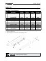
1
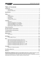
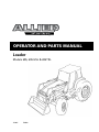
Operator and Parts Manual
Loader
Models 695, 695 HSL & 695 TSL
122011
P3688
Table of Contents - 695 Loader
Table of Contents
Introduction..................................................................................................................................4
• Terminology......................................................................................................................4
• Hydraulic (Hose Kit)..........................................................................................................5
Specifications................................................................................................................................6
Safety.............................................................................................................................................8
• Safety.................................................................................................................................8
• General Safety...................................................................................................................9
• Installation.........................................................................................................................9
• Safety Decals...................................................................................................................10
• Important Precautions.................................................................................................... 11
Operation....................................................................................................................................12
• Operation.........................................................................................................................12
• Operating Suggestions for Loading..............................................................................13
• Operating Suggestions for Backfilling..........................................................................14
• Attaching the Loader to Your Tractor..............................................................................15
• Removing the Loader from Your Tractor........................................................................17
General Instructions...................................................................................................................19
HSL General Note and Instructions..........................................................................................20
TSL General Note and Instructions...........................................................................................21
Troubleshooting..........................................................................................................................22
Maintenance...............................................................................................................................24
• Lubrication.......................................................................................................................24
Bolt Torque..................................................................................................................................25
• Checking Bolt Torque......................................................................................................25
Parts.............................................................................................................................................26
• Sub Frame Assembly Drawing and Parts List..............................................................26
• Main Frame Assembly Drawing and Parts List.............................................................28
• Main Frame Assembly Drawing and Parts List - TSL...................................................30
• Hydraulic Plumbing Assembly and Parts List...............................................................32
• Hydraulic Plumbing Assembly and Parts List - HSL.....................................................34
• Hydraulic Plumbing Assembly and Parts List - TSL......................................................36
Assembly.....................................................................................................................................38
• Hydraulic Cylinder Assembly.........................................................................................38
Pre-delivery Check List...............................................................................................................39
Warranty......................................................................................................................................40
Manufacturer’s statement: for technical reasons Buhler Industries Inc. reserves the right to modify
machinery design and specifications provided herein without any preliminary notice.
Information provided herein is of descriptive nature. Performance quality may depend on soil fertility,
applied agricultural techniques, weather conditions and other factors.
3
Introduction - 695 Loader
Introduction
Allied by Farm King front-end loaders are backed by years of extensive research. Factory testing
simulates specific operations to evaluate durability; days of continuous cycling in raising, twisting
and dropping loads using a programmed hydraulic power unit represents years of extreme use.
With one of the largest mounting kit application lists in the industry, there is an Allied front-end
loader available for nearly every tractor, large or small, new or old. Custom colors are available to
match all tractor brands which adds resale value and visual appeal.
Keep this manual handy for frequent reference. All new operators or owners must review the
manual before using the equipment and at least annually thereafter. Contact your Allied by Farm
King Dealer if you need assistance, information, or additional copies of the manual. Visit our
website at www.buhlerindustries.com for a complete list of dealers in your area.
The directions left, right, front and rear, as mentioned throughout this manual, are as seen facing
in the direction of travel of the implement.
Terminology
Basic terminology used throughout this manual has been identified below. For part numbers and
further details refer to the Parts section.
4
Introduction - 695 Loader
Hydraulic (Hose Kit)
Hose Kit “A”
Loader powered by the tractor remotes.
Consists of four hoses leading from loader
tubing to tractor remote couplers
Hose Kit “B”
Loader operated by an external OC or CC valve
that is powered from the tractor remotes.
Hose Kit “C”
Loader operated by an external valve that is
plumbed into the tractor hydraulic system.
Consists of 4 hoses leading from loader tubing
to external mounted valve plus the necessary
fittings, hoses and adapter blocks (if necessary)
to tap into tractor hydraulic system. Use valve
type shown with hose kit “C”
5
Specifications - 695 Loader
Specifications
6
Specifications - 695 Loader
Model number: 695
Mounting height: 39.5" (nominal)
Typical range: 40.0
Description
Bucket
Lifting
Leveling
TSL Bucket
Bore
3.00"
3.00"
3.50"
3.00"
Rod
1.75"
1.75"
1.75"
1.75"
Stroke
26.50"
30.00"
12.00"
22.00"
A - Maximum lift height: 161" (13.4')
B - Clearance with bucket dumped: 117" (9.8')
C - Reach at full height: 21"
D - Maximum dump angle: 60°
D - TSL max dump angle at ground: 60°
D1 - TSL dump angle at ground: 90°
F - Bucket rollback angle ground: 32°
F - TSL bucket rollback angle: 37°
G - Digging depth: 5"
H - Overall height in carry position: 84" (7")
R - Rollback angle at full height: 121.5°
R - TSL bucket rollback angle at full lift: 52°
Calculated breakout force: 5615 lbs
Calculated lift capacity: 3165 lbs
Notes:
1 - Calculated values assume 2500 psi cylinder pressure
2 - Breakout force estimated as per ASAE S301.2 - 4.1.2 (net payloud applied at cutting edge)
3 - Lift capacity estimated a per ASAE S301.2 - 4.1.1 (payload applied at bucket midpoint)
4 - Average bucket weight (72°): 450 lbs
7
Safety - 695 Loader
Safety
Safety Instructions
Remember, YOU are the key to safety. Good safety practices not only protect you, but also the
people around you. Make these practices a working part of your safety program. Be certain that
everyone operating this equipment is familiar with the recommended operating and maintenance
procedures and follows all the safety precautions. Most accidents can be prevented. Do not risk
injury or death by ignoring good safety practices.
The alert symbol is used throughout this manual. It indicates attention is required and identifies
hazards. Follow the recommended precautions.
The safety alert symbol means…
ATTENTION! BECOME ALERT! YOUR SAFETY IS INVOLVED!
8
Caution
The caution symbol indicates a potentially hazardous situation
that, if not avoided, may result in minor or moderate injury. It
may also be used to alert against unsafe practices.
Warning
The Warning Symbol indicates a potentially hazardous situation
that, if not avoided, could result in death or serious injury, and
includes hazards that are exposed when guards are removed. It
may also be used to alert against unsafe practices.
Danger
The Danger Symbol indicates an imminently hazardous situation
that, if not avoided will result in death or serious injury. This
signal word is to be limited to the most extreme situations,
typically for machine components that, for functional purposes,
cannot be guarded.
Safety - 695 Loader
General Safety Instructions
• Have a first-aid kit available for use and know how to use it.
• Have a fire extinguisher available, stored in a highly visible location, and know how to use it.
• Wear appropriate protective gear. This list may include but is not limited to:
-- hard hat
-- protective shoes with slip resistant soles
-- protective glasses or goggles
-- heavy gloves
-- wet weather gear
-- hearing protection
-- respirator or filter mask
• Read and understand the Operator’s Manual and all safety signs before operating, servicing,
adjusting, repairing, or unplugging the equipment.
• Never work beneath raised loader unless it is securely supported. The following are
instructions for the lift lock supports.
• Do not pivot or turn tractor with bucket raised, except at a minimum speed. Always make
allowance for length of loader when making turns.
• Never leave tractor unattended while the bucket is raised. Always lower bucket to the ground
and shut off before leaving the tractor seat.
• Do not walk under raised bucket.
• Never operate loader while operator is not seated in the driver's seat on the tractor.
• Keep tractor on solid ground. Loose fill, rocks and holes can be dangerous for loader
operation or movement.
• Never operate a loader with frayed or damaged hoses or leaking fittings.
• Add ballast as required to ensure 25% of gross vehicle weight is transferred to the rear axle.
• Space rear tires as recommended by tractor manufacturer. Maximize width for high lift
applications.
• Do not raise bucket to extreme heights while tractor is on an incline. Carry loader low for
safety. Load center when bucket is raised on a slope. Be alert for terrain changes and adjust
bucket accordingly. Keep bucket low, no more than one foot high, as long as possible.
• Note: A pivoting front axle acts like a three-wheeled tractor until the stops hit the axle.
• If the cylinders are used to raise front wheels of tractor for service, place blocks under tractor
before working around front end.
Installation
• To install safety signs, ensure the installation area is clean and dry. Decide on the exact
position before you remove the backing paper. Remove the smallest portion of the split
backing paper and align over the specified area. Carefully press in place.
• Slowly peel back the remaining paper and smooth the remaining portion in place. Small air
pockets can be pierced with a pin and smoothed out.
9
Safety - 695 Loader
Safety Decals
10
Safety - 695 Loader
Important Precautions
11
Operation - 695 Loader
Operation
Operation
General Operating Notes:
Refer to tractor Operator's Manual for Operating information on the tractor's hydraulic system.
Hydraulic systems using auxiliary valves should have them located for easy reach from the tractor
seat. Hoses should be connected in such a manner that pushing forward on valve handles lowers
the boom or dumps the bucket
Warning
Always connect boom hoses to float section.
Weight added to rear of tractor provides better
traction and an easier, more efficient loader
operation. Extra weight along with the rear wheels,
reduces the risk of roll-over.
The smaller the tractor is, the easier it will roll. We
recommend that weight be added to rear tires with
liquid or by the installation of rear wheel weights.
Where additional weight is required, a counterweight
box can be fabricated for tractors with three-point
hitches.
Extra weight can also be added by the use of a heavy
implement mounted to the three-point hitch.
A roll-over protective structure is also recommended.
In cold weather, operate the tractor's engine at idle
speed until the hydraulic fluid is warmed up. High
engine speed when the hydraulic fluid is cold will
cause the pump to wear prematurely.
Under normal conditions, operate the tractor's engine
at 1/2 throttle. Shift the tractor into a low gear before
entering a pile of material to minimize strain on
loader arms.
12
Operation - 695 Loader
Operating Suggestions for Loading
When handling heavy loads, be sure to lower lift arms slowly. This is known as feathering the
hydraulic lever. If load is lowered too fast and stopped suddenly, excessive shock loads are created
which can damage loader or tractor.
When loading bucket, drive straight into material. Attempting to turn tractor while loading bucket
can cause damage to both the loader and tractor.
Note: Bottom surface of bucket is parallel to
line on motion.
To increase loading efficiency. Minimize angle
of turn and length to run between pile and
spreader.
Work both levers back to direct pressure to
both cylinders.
Leave material, which drifts over the bucket sides
for final cleanup.
Combined action of lift and bucket cylinders
increases loading efficiency.
A straight bottom offers more resistance to lift.
13
Operation - 695 Loader
Operating Suggestions for Backfilling
DO THIS
When backfilling approach pile with a flat
bucket. Leave dirt in bucket. Dumping on each
pass wastes time.
Backgrade work surface with a loaded bucket.
Release all pressure on lift cylinders so full
weight of bucket is scraping ground. Use heel
of bucket
Do not use bucket in dumped position for
bulldozing. This will only impose severe shock
loading on the bucket cylinders and make it
more difficult to maintain a level grade.
Warning
14
Do not use loader as battering ram!
Operation - 695 Loader
Attaching the Loader to Your Tractor
1. Postions the tractor as centrally as possible and drive, using lowest gear possible, into the
loader frame until hoses can be connected.
2. Couple up the hydraulic hose lines to the loader or tractor valve ensuring proper function (see
operator and maintenance section)
NOTE: When mounting the loader for the first time, slowly work the cylinders back and forth,
so that most of the air is removed Loosen the bolts on the hooks so that they can be moved.
Also, check that the nuts in the rear of the subframe are in line with the holes.
3. On some tractors, the lift cylinders may have to be extended slightly, so that the subframes can
clear the front axle. Do not extend the cylinders more than is required.
On self leveling loaders, the bucket will dump
at the same time the loader is raised. Therefore,
Operate both hydraulic levers together.
4. Drive the tractor ahead until the subframe is past the front axle and the front hook is close to
mounting boss.
Check front grille clearance during installation to
avoid tractor damage.
5. Retract or extend the lift cylinders to line up the front hook with the mounting boss.
On self leveling loaders, the bucket will roll back
at the same time the loader is lowered. Therefore,
operate both hydraulic levers together.
6. When the hook is lined up, dump or roll back the bucket to lower or raise the subframe upright
to align with the mounting boot.
15
Operation - 695 Loader
7. Continue to drive the tractor forward until the subframe uprights are seated in the boot.
8. Secure the subframe uprights with the bolts and washers. Torque 500 ft-lb.
When mounting for the first time, the front hook
bolts will have to be tightened after positioning
the hook directly over the mounting boss (most
rearward position)
9. Raise the loader and lock the support stand tubes in the up position.
When mounting for the first time, raise the loader
slowly and check to make sure that the hoses do
not bind or become pinched in all positions. Work
the loader and bucket up and down to work out
all the air in the hydraulics. Check and refill the
tractor's hydraulic system.
16
Operation - 695 Loader
Removing the Loader from Your Tractor
Warning
When removing the loader, it must be fitted with a bucket or other
suitable attachment to give the frame stability after removal. If
this is not done, the frame will not remain standing.
Warning
Always remove the loader on firm, level ground (away from
children's play area and high traffic areas). This makes attaching
and removing much faster and easier. It also makes the free
standing loader more stable.
1. Raise the loader, lower support stand tubes and lock into position.
2. Lower the loader until the stand tubes are firmly on the ground and then dump the bucket so
that it is also firmly on the ground. there should be slight downward pressure.
3. Loosen the bolts from the rear of the subframe boots and swing bolt up into lock position.
17
Operation - 695 Loader
4. Roll back the bucket slightly and simultaneously extend or retract the lift cylinders to free hooks
from spools. Then slowly back up the tractor.
5. Once the subframe is clear of the boot and the hook is clear of the mounting boss, roll back the
bucket all the way. This raises the rear uprights of the loader.
On some mountings, the lift cylinders must be
extended more while the tractor is backing up,
so that the subframes clear the front axle.
6. Continue backing up until the loader is clear.
Be sure the hoses do not get pinched or catch on
any frame members while backing up.
7. After the loader is clear, retract the lift cylinders to protect the shafts and disconnect the
hydraulic lines at quick couplers.
18
General Instructions - 695 Loader
General Instructions
As with any piece of equipment, the care with which your loader is operated and maintained
will greatly affect it’s life and the safety of the people using it.
1. Keep all pivots well lubricated for longer bushing life. Inspect every 500 hours of operationfor
wear.
2. Periodically check all bolts for tightness. If any bolt is damaged, replace it with a bolt
ofequivalent grade or strength.
3. Follow the recommendations of the tractor manufacturer in regards to the quantity of oil used.
4. Check oil level frequently to ensure the system is full.
5. When making an oil check, be sure lift cylinders are retracted.
6. Before operating the loader, particularly if the loader is left standing for any length of time,
check the hydraulic system and oil level.
7. When installing hydraulics, follow the circuit carefully. See hydraulic hook-up section and make
sure the hoses do not contact any hot manifolds or sharp edges on tractor. After assembly,
raise the loader slowly and check to make sure that the hoses do not bind in all positions.
8. The pressure of the relief and open center valves is set at the factory. Do not tamper with the
setting, serious injury to the operator or damage to the loader or tractor hydraulics may occur.
Warranty will be void if the loader is operated above recommended pressure.
9. When servicing any hydraulic components, care must be taken to prevent any foreign matter
from entering the system.
10. Do not neglect oil leaks. Leaks affect loader operation, are dangerous and can result in
personal injury or damage to the hydraulic system.
11. Never leave the cylinder shafts exposed when loader is not in use.
12. Worn or damaged components should be replace as soon as possible with only the
manufacturer’s recommended component or equivalent.
19
HSL General Note and Instructions - 695 Loader
HSL General Note and Instructions
1. The hydraulic self-leveling system (HSL) utilizes two metering cylinders which displace oil
into or out of the bucket cylinders as the loader is raised or lowered. The cylinder volumes and
geometry’s are carefully matched for each loader model to provide the correct amount of oil to
keep the bucket level after it is initially leveled.
2. The HSL system incorporates two relief valves which are only utilized if the bucket cylinders
are at either end of the stroke. If the loader is raised with the bucket fully dumped, oil will be
bypassed at high pressure into the lower side of the lift cylinder circuit. If the loader is lowered
with the bucket fully rolled back, oil will be bypassed at high pressure into the raised side of
the lift cylinder circuit. Note that these two conditions are likely to occur only intermittently,
and although the pump will be forced to supply oil at a higher pressure no damage to the
loader components will occur. It is, however, recommended to avoid the above situations and
keep the bucket somewhat level while raising or lowering the loader for smoother operation.
3. Note that the large volume (piston side) of the leveling cylinders is connected to the large
volume of the bucket cylinders, and the small volume (rod side) is connected between the two
sets of cylinders. The effect of this configuration is to create a breakout force “boost” if the
bucket cylinders are pressurized toward the rollback position during breakout.
4. The opposite effect of the above situation is that the loader will have poor lift capacity if lifting
with the bucket cylinders pressurized in the dumped position. This is, however, a very unlikely
occurrence (lifting a load with bucket fully dumped).
5. The cartridge style relief valves are factory set at 2,000 psi cracking pressure and are capable of
bypassing 15-20 GPM. If loader lock-up should occur due to a low tractor relief setting, higher
inlet flows or return line restrictions, the relief valve setting may be bucket off slightly until the
lock-up condition is overcome (as described in note 2 above).
6. Never utilize the leveling cylinders to raise the loader. This could occur if the lift cylinders are
placed in float while the bucket cylinders are held pressurized in the retracted position. If the
loader should rise, pressurize the lift cylinders to lower it; otherwise a rapid drop may occur
when the bucket cylinders are extended. Note that this situation is unlikely to occur during
normal loader operation and is possible only with a lightly loaded bucket.
20
TSL General Note and Instructions - 695 Loader
TSL General Note and Instructions
1. The true self leveling system (TSL) utilizes mechanical linkages to maintain bucket level
while raising and lowering. The pivot plate weldment, leveling tubes and linkages have been
developed to ensure that the bucket remains at the same position throughout its range of
motion. This feature is standard with 2.50" and 3.00" diameter bucket cylinders.
2. The TSL system incorporates a relief and anticavitation manifold to provide extra dump at
ground and rollback at full lift height. This feature is available on 3.00" bucket cylinders only.
If the loader is raised with the bucket fully dumped, oil from the bucket piston side will be
bypassed at high pressure to the bucket shaft side and the lift shaft side as the quickattach
contacts the dump stop. If the loader is lowered with the bucket fully rolled back, oil from
the bucket shaft side will be bypassed at high pressure to the bucket piston side and the lift
piston side will provide makeup as the quick attach contact the rollback stop. Note that these
two conditions are likely to occur intermittently and although the pump will be forced to
supply oil at a higher pressure, no damage to the loader components will occur. It is, however,
recommended to avoid the above situations and keep the bucket somewhat level while raising
or lowering the loader for smoother operation.
3. The extra bucket stroke length allows for the bucket to be dumped to approximately 90° at
ground. This allows for bucket assist when traction is minimal. If the loader is raised from this
position, the bucket will retract as the quick attach contacts the dump stop and the circuit goes
through relief as described in note 2.
4. Extra bucket retraction allows for the bucket to be rolled back as the loader raises. The TSL
feature maintains the bucket level, but as required the bucket can be manually rolled back
approximately 20° to allow for increased bucket capacity. If the loader is lowered from this
position, the bucket will extend as the quick attach contacts the rollback stop and the circuit
goes through relief as described in note 2.
5. The relief valve is factory set at 3250 PSI cracking pressure and is capable of bypassing 10-15
GPM. If loader lock-up should occur due to a low tractor relief setting, higher inlet flows or
return line restrictions, the relief valve may be backed off slightly until the lock-up condition is
overcome (counterclockwise turn of set-screw). Contact the factory for further instructions.
21
Troubleshooting - 695 Loader
Troubleshooting
Problem
Loader slow and/or will
not dump
Loader chatters or vibrates
when raising and lowering
Excessive movement at
pivots
Possible Cause
Quick couplers leaking
Hydraulic oil too heavy
Change or replace filter
Oil filter plugged
Clean or replace filter
Hydraulic pump worn
Repair or replace pump
Oil line restricted or leaking
Replace damaged or restricted
hoses or tube lines
Inspect, clean, repair or replace
valve
Air in hydraulic system
Cycle lift cylinders and bucket
cylinders several times to free
system of air
Cylinder leaks internally
Replace seals
Faulty valve
Repair or replace valve
Air leak in pump inlet line
Check, tighten or replace inlet
line
Air in hydraulic system
Cycle lift cylinders and bucket
cylinders
Oil level too low
Add oil as required
Worn bushings and/or pins
Replace bushings and/or pins
Pump noisy
22
Check all hoses and tubes for
leaks, damage or restrictions
Control valve does not shift
properly
Inlet line restricted or leaking
Oil leaks
Remedy
Check connections and
compatibility or replace
Check for air leaks, restrictions
or collapsed hose
Tighten or replace hose
Clean filter if necessary
Oil level too low
Add oil as required
Pump worn or damaged
Repair or replace pump
Damaged fitting or hoses
Replace damaged parts
Loose connections
Tighten fittings
Worn or damaged o-ring wiper
Install a seal repair kit
seal in cylinder rod end
Troubleshooting - 695 Loader
Problem
Insufficient lift capacity
Possible Cause
Remedy
Improper hydraulic pump
operation
Repair or replace pump
Load is greater than boom
lift capacity
Check loader specifications
Internal boom cylinder
leakage
Replace any worn parts and
install a seal repair kit
Improper hydraulic valve
operation
Repair or replace valve
Worn control valve
Worn cylinder piston seals
Have authorized dealer
replace seals
Excessive wear on bottom of
bucket and wear pads
Float position not used while
operating loader
Use float position provided on
valve
Hydraulic cylinders inoperative
Hose from control valve
improperly connected
Refer to plumbing diagrams
Tractor control valve relief
stuck open
See your service manual for
proper adjustment
Incorrect Auxiliary Valve
Check with loader dealer for
proper valve application
Hydraulic control valve set to
low
Adjust valve in accordance
with manual
Slow leak down
Pump operating continually
on closed center tractor
hydraulics system
Loader lift and bucket tilt
controls do not work according Hoses improperly connected
to decal
Refer to plumbing diagrams
and correct hose connections
Open center control valve on
closed center tractor
Replace relief valve with
closed center plug and plug
the power beyond adapter on
valve
Valve noisy and/or hot
Install open center plug on
optional valve
Tractor loads/pump squeals
Closed center control valve
on open center tractor
Replaceclosed center plug
with relief and install short
plug in place of the power
beyond adapter
23
Maintenance - 695 Loader
Maintenance
Lubrication
Lubricate tractor hydraulic unit as indicated in tractor operator's manual. Keep bushings on lift arm
pivots and cylinders well lubricated. Use high-grade lithium grease every 8 hours of operation.
NOTE: Frequent greasing will prevent contaminants from migrating between the pins and bushings
24
Bolt Torque - 695 Loader
Bolt Torque
Checking Bolt Torque
The tables shown below give correct torque values for various bolts and hex bolts. Tighten all bolts
to the torques specified in chart unless otherwise noted. Check tightness of bolts periodically, using
bolt torque chart as a guide. Replace hardware with the same strength bolt.
Standard Bolt Torque
Bolt Size
(in)
Grade 2
Grade 5
Grade 8
Torque
Torque
Torque
ft-lb
NM
ft-lb
NM
ft-lb
NM
0.25
0.313
0.375
6
11
20
7
15
27
8
17
31
11
23
41
12
25
44
16
33
60
0.438
0.5
0.563
32
49
70
43
66
95
49
76
109
66
103
148
70
106
153
95
144
207
0.625
0.75
0.875
97
144
166
131
195
225
150
266
430
203
360
583
212
376
606
287
509
821
1
1.125
1.25
250
354
500
339
480
678
644
795
1120
873
1077
1518
909
1288
1817
1232
1745
2462
1.375
1.5
655
870
887
1179
1470
1950
1992
2642
2382
3161
3228
4283
Metric Bolt Torque
Bolt Size
(mm)
Class 5.6
Grade 8.8
Grade 10.9
Grade 12.9
Torque
Torque
Torque
Torque
ft-lb
NM
ft-lb
NM
ft-lb
NM
ft-lb
NM
6
8
10
3.1
7.7
15
4.3
10.5
21
7.3
17.7
35
9.9
24
48
10.3
25
49
14
34
67
12.1
29
59
16.5
40
81
12
14
16
26
42
64
36
58
88
61
97
147
83
132
200
86.2
136
210
117
185
285
103
162
250
140
220
340
18
20
22
89
126
169
121
171
230
202
287
390
275
390
530
287
405
549
390
550
745
346
486
656
470
660
890
24
27
30
217
320
435
295
435
590
497
733
995
675
995
1350
708
1032
1401
960
1400
1900
840
1239
1681
1140
1680
2280
33
36
39
590
759
988
800
1030
1340
1349
1740
2249
1830
2360
3050
1902
2441
3163
2580
3310
4290
2278
2935
3798
3090
3980
5150
25
Parts - 695 Loader
Sub Frame Assembly
26
Parts - 695 Loader
Description
Qty
Reg
Qty
HSL/TSL
Item
Part #
1
31423
695 Sub Frame Weldment Left
1
2
31424
695 Sub Frame Weldment Right
1
1
31425
695 HSL Sub Frame Weldment Left
1
2
31426
695 HSL Sub Frame Weldment Right
1
3
110959
Hook Weldment
2
2
4
112747
Plate Clamp
2
2
5
112746
Spacer Block
4
4
6
112748
Shim
2
2
7
112663
Cross Member Weldment
1
1
8
112668
Tube Cross Member
1
1
9
112642
Shaft Pivot 1.75 Dia x 5.50 Lg
2
2
10
113281
Bolt Retainer Weldment
2
2
11
110887
Loader Lift Lock Weldment
2
2
12
812717
Grommet 0.375 Id x 1.00 Od x .13
2
2
13
812026
Bolt Hex 0.313Nc x 1.00 Gr5 Pl
2
2
14
812944
Bolt Car. 0.625Nc x 3.00 Gr5 Pl
8
8
15
84127
Bolt Car. 0.625Nc x 3.50 Gr5 Pl
2
2
16
812939
Bolt Hex 0.875Nc x 10.00 Gr8 Pl
2
2
17
81967
Nut Lock (Nylon) 0.625Nc Grb Pl
14
14
18
81723
Washer Lock 0.875 Pl
2
2
19
112730
Washer Boot
2
2
20
112812
*Decal General Caution
2
2
21
113434
*Decal - 695 x 1.40
2
2
22
112983
*Decal - Warning Overhead Hazard
2
2
23
112982
*Decal - Lift Lock Instruction
2
2
24
812882
Bolt Car. 0.625Nc x 2.50 Gr5 Pl
4
4
25
113474
*Decal - Cross Member Caution
2
2
26
24329
Mounting Wrench (For 0.875 Bolt)
1
* Part of decal replacement kit X1256
27
Parts - 695 Loader
Main Frame Assembly - HSL
28
Parts - 695 Loader
Item
Part #
Description
Qty 795
TSL
Qty
S795 TSL
1
31435
695 Main Frame Weldment
1
31436
695 HSL Main Frame Weldment
1
1
2
24439
Quick Attach Weldment Left
1
3
24438
Quick Attach Weldment Right
1
4
112798
Tube Cross Qtach
1
1
5
108827
Pin Weldment
2
2
6
111231
Stand Weldment
2
2
7
113114
Strap Stand
2
2
8
24329
Wrench Mounting
1
1
9
110907
Pin 0.625 Dia. Stand
2
2
10
12779
Hair Pin Clip #9 Western Wire
5
5
11
113109
Levelling Rod
1
1
12
112954
Pin 1.25 Dia. x 6.75 Long
4
6
13
112955
Pin 1.25 Dia. x 5.00 Long
4
6
14
117371
Pin Qtach
2
2
15
112659
Bushing 1.25 ID x 1.50 OD x 1.375 Long
16
16
16
24242
Tube Cover
1
1
17
24447
3.0 Dia. x 26.50 Bucket Cylinder
2
2
18
24314
3.0 Dia. x 30.00 Lift Cylinder
2
2
19
24319
3.5 Dia. x 12.00 Leveling Cylinder
20
81581
Bolt Hex 0.375nc x 2.50 gr5 pl
20
24
21
81669
Bolt Hex 0.625nc x 3.50 gr5 pl
4
4
22
81592
Nut Hex 0.375nc gr2 pl
4
4
23
81344
Nut Lock (nylon) 0.375nc grB pl
24
28
24
81967
Nut Lock (nylon) 0.625nc grB pl
6
6
25
812941
Washer Grip 0.375 pl
1
1
26
81570
Washer Flat Std. 0.375 hs pl
4
4
2
2
10ft
10ft
2
27
23842
*Decal - Hyd. Self Level x 0.75
28
813356
*Decal - Buhler Allied x 1.75
29
52281-000
30
113155
Pin 1.25 dia. x 9.0 lg
4
4
31
117372
Pin 1.25 dia. x 7.63 lg
2
2
*Bright Orange Scotchcal #72368
2
32
113134
695 Link Weldment 16.0
4
4
33
113051
695 Link 9.0
4
4
34
113691
Bushing 1.25 ID x 1.50 OD x 0.75
8
8
35
113690
Pivot Tube
2
2
36
84583
Grease Fitting, 1/8" npt straight
2
2
37
84268
Bolt hex 0.625nc x 1.50 gr5 pl
2
2
38
113488
*Decal - Quick Attach Instruction
2
2
* Part of decal replacement kit X1256
29
Parts - 695 Loader
Main Frame Assembly - TSL
30
Parts - 695 Loader
Item
Part #
Description
Qty
1
24712
695 TSL Mainframe
1
2
24717
Quick Attach Left
1
3
4
5
6
7
8
9
10
11
12
13
14
15
16
17
18
19
20
21
22
23
24
25
26
27
28
29
30
31
32
33
34
35
36
37
38
39
40
41
42
43
24716
112798
108827
114296
114303
113690
110907
12779
114170
112954
112955
117371
113999
24242
24708
24314
114252
81581
81669
81592
81344
81967
113691
81570
113633
113766
114104
113697
117372
114119
114120
81966
84583
FNH114039
FNH114040
114097
114101
113998
113995
813228
81637
Quick Attach Right
Cross Tube
Pin Weldment
Stand Tube
Stand Foot
Link Spacer
Stand Pin 0.625 Diameter
Hair Pin Clip
Leveling Rod
Pin 1.25 x 6.75 Lg
Pin 1.25 Dia x 5.00 Lg
Pin 1.25 Dia x 6.13 Lg
Leveling Tube
Cross Tube Cover
Cylinder Bucket
Cylinder Lift
Pin 1.25 Dia. x 6.75 Lg
Hex Bolt 0.375 Dia x 2.5 Lg
Hex Bolt 0.625 Dia x 3.5
Hex Nut 0.375 Dia
Locknut 0.375 Dia
Locknut 0.625 Dia
Bushing 1.25 I.D. x 1.63 O.D x 0.75" Lg
Flat Washer 0.375 Dia
Bushing 1.25 I.D. x 1.63 O.D. x 1.88" Lg
Bushing 1.25 I.D. x 1.50 O.D. x 1.38" Lg
Pin 1.25 Dia x 7.48
Pin 1.25 Dia x 8.63 Lg
Pin 1.25 Dia x 7.63 Lg
Link Weldment Left
Link Weldment Right
Locknut 0.50 Dia
Grease Fitting 1/8 Npt Straight
Bolt Plate
Rod Guide
Link Assembly 11.25
Pivot Plate Left
Pivot Plate Right
Pin 1.25 Dia x 7.13 Lg
1/2" Wing Nut (Pl)
1/2" Lock Washer (Pl)
1
1
2
2
2
2
2
2
1
2
2
2
2
1
2
2
4
28
4
4
37
4
8
4
4
20
4
4
2
2
2
2
2
1
1
4
1
1
2
2
2
31
Parts - 695 Loader
Hydraulic Plumbing Assembly
32
Parts - 695 Loader
Item
Part #
Description
Qty 595
1
24458
Bucket Cylinder
2
2
24454
Lift Cylinder
2
3
812973
3/8 x 12" Hose 3/4 Morb x 3/4 Swfjic
2
4
811754
3/8 x 18" Hose 3/4 Morb x 3/4 Swfjic
2
5
812703
3/8 x 22" Hose 3/4 Morb x 3/4 Swfjic
2
6
812947
3/8 x 22" Hose 3/4 Swfjic x 3/4 Swfjic
2
7
113222
Tubing - Lift Cyl. Bottom Raise
1
8
113223
Tubing - Lift Cyl. Top Drop
1
9
113031
Tubing - Lift Cyl. Comm. (23.0")
1
10
112937
Tubing - Lift Cyl. Comm. (31.0")
1
11
113224
Tubing - Bucket Cyl. Bottom Rollbk
1
12
113225
Tubing - Bucket Cyl. Top Dump
1
13
112837
Tubing - Bucket Cyl. Cross Tube
2
14
812128
Elbow 90 3/4 Mjic x 3/4 Mjic
4
15
811414
Elbow 90 3/4 Morb x 3/4 Mjic
2
16
812069
Tee 3/4 Mjic
4
17
11362
Clip Pipe Std.
10
18
81592
Nut Hex 0.375Nc Gr2 Pl
4
19
81344
Nut Lock (Nylon) 0.375Nc Grb Pl
6
33
Parts - 695 Loader
Hydraulic Plumbing Assembly - HSL
34
Parts - 695 Loader
Item
Part #
Description
Qty
1
24319
3.5 Dia. x 12.00 Cyl. Assy. Level
2
2
24447
3.0 Dia. x 26.50 Cyl. Assy. Bucket
2
3
24314
3.0 Dia. x 30.00 Cyl. Assy. Lift
2
4
811572
3/8 x 15" Hose 3/4 Swfjic x 3/4 Morb
2
5
811754
3/8 x 18" Hose 3/4 Swfjic x 3/4 Morb
2
6
812703
3/8 x 22" Hose 3/4 Swfjic x 3/4 Morb
2
7
812697
3/8 x 24" Hose 3/4 Swfjic x 3/4 Swfjic
3
8
811466
3/8 x 24" Hose 3/4 Swfjic x 3/4 Morb
3
9
811434
3/8 x 30" Hose 3/4 Swfjic x 3/4 Morb
1
10
811424
3/8 x 30" Hose 3/4 Swfjic x 3/4 Swfjic
1
11
113222
Tubing - Lift Cyl. Bottom Raise
1
12
113223
Tubing - Lift Cyl. Top Drop
1
13
113031
Tubing - Lift Cyl. Comm. (23.0")
1
14
112937
Tubing - Lift Cyl. Comm. (31.0")
1
15
113224
Tubing - Bucket Cyl. Bottom Rollbk
1
16
113225
Tubing - Bucket Cyl. Top Dump
1
17
112837
Tubing - Bucket Cyl. Cross Tube
2
18
113220
Tubing - Bucket Cyl. Bott Ext Hsl
1
19
113221
Tubing - Bucket Cyl. Top Ext Hsl
1
20
23875
Valve Relief Assembly
2
21
811414
Elbow 90 3/4 Morb x 3/4 Mjic
4
22
812069
Tee 3/4 Mjic
8
23
812786
Tee 3/4 Mjic x 3/4 Swfjic
2
24
812828
Tee 3/4 Morb x 3/4 Mjic x 3/4 Mjic
2
25
11362
Clip Pipe Std.
11
26
81592
Nut Hex 0.375Nc Gr2 Pl
4
27
81344
Nut Lock (Nylon) 0.375Nc Grb Pl
7
35
Parts - 695 Loader
Hydraulic Plumbing Assembly - TSL
36
Parts - 695 Loader
Item
Part #
Description
Qty
1
24314
3.0 Dia x 30.00 Cylinder Assembly Lift
2
2
24708
3.0 Dia x 22.00 Cylinder Assembly Bucket
2
3
812069
Tee 3/4-16Mjic x 3/4-16 Mjic
6
5
811414
Elbow 90° 3/4-16 Morb To 3/4 Mjic
2
6
812829
Elbow 90° 3/4 Swfjic x 3/4 Mjic
2
7
11362
Pipe Clip
9
8
113031
Tubing Ext. Lift Cyl 23.0"
2
9
114114
Tubing Lift Cyl. (Bottom, Raise)
1
10
114115
Tubing Lift Cyl. Right (Top, Drop)
1
11
114116
Tubing Bucket Cyl. (Bottom, Dump)
1
12
114117
Tubing Bucket Cyl. (Top, Rollback)
1
13
114118
Tubing Lift Cyl. Left (Bottom, Raise)
1
14
112837
Tubing Cross Tube
2
15
811754
Hose 3/8 x 18 3/4-16 Morb x 3/4-16 Swjic
2
16
812697
Hose 3/8 x 24 3/4-16 Swfjic x 3/4-16 Swfjic
2
17
114605
Hose 3/8 x 24 3/4-16 Morb x 3/4-16 Swfjic
4
18
811434
Hose 3/8 x 30 3/4-16 Morb x 3/4-16 Swfjic
4
19
114174
Tubing Lift Cylinder Left (Top, Drop)
1
20
25253
TSL Manifold
1
21
812786
Tee 3/4 Mjic x Run x 3/4 Swfjic
2
22
812052
Bolt Hex 0.250Nc x 3.00 Gr5 Pl
2
23
81922
Nut Lock (Nylon) 0.25Nc Grb Pl
2
*Required only if cartridge valve kit X2264 not purchased
37
Assembly - 695 Loader
Assembly
Hydraulic Cylinder Assembly
Item
Description
Bucket
Cylinders
TSL Bucket
Cylinders
Lift
Cylinders
Leveling
Cylinders
Diameter
3.00"
3.00"
3.00"
3.50"
Length of Stroke
26.50"
22.00"
30.00"
12.00"
Retracted Length
36.50"
51.75"
41.50"
22.00"
Extended Length
63.00"
73.75"
71.50"
34.00"
Cylinder Assembly
24447
24708
24314
24319
Seal Kit
X1424
X1424
X1424
X1655
Shaft Diameter
1.75"
1.75"
1.75"
1.75"
Head Plate
24606
24606
24606
24316
2
Shaft Weldment
113198
113928
112873
112934
3
Cylinder Tube Weld't
24449
24713
24313
24317
4
Piston Half (wide)
112862
112862
112862
112659
5
Piston Half (narrow)
112863
112863
112863
112941
6
Self-Locking Nut
810457
810457
810457
810457
7
Shaft Bushing
113766
113578
113766
113766
1
1. Bucket cylinder shown.
2. All cylinder seals are contained in corresponding seal kit.
caution
38
Maximum pressure - 2750 psi
Safety - 695 Loader
Pre-delivery Check List
Before delivering this equipment please complete the following check list.
__ 1. The loader has been installed using the appropriate mounting kit for the tractor and loader.
__ 2. The hydraulic system installed is appropriate for the tractor and loader.
__ 3. The loader is properly installed.
__ 4. All bolts are tightened to the torque specifications shown in the torque chart.
__ 5. All safety decals are readable.
__ 6. The loader has been tested and operates properly.
__ 7. The operator's manual has been delivered to the owner who has been instructed on the safe
and proper use of the loader.
Dealer's Signature:
This check list is to remain in this owner's manual and is the responsibility of the dealer to
complete it before delivery to the customer.
39
Warranty - 695 Loader
Allied by Farm King Limited Warranty
This document limits your warranty rights.
Base Limited Warranty
Buhler Industries Inc. provides this warranty only to original retail purchasers of its product.
Buhler Industries Inc. warrants to such purchasers that all Buhler Industries Inc. manufactured
parts and components used and serviced as provided for in the Operator’s Manual shall be free
from defects in materials and workmanship for a period following delivery to the original retail
purchaser of 12 months (80 days for commercial applications). This limited warranty applies only
to those parts and components manufactured by Buhler Industries Inc. Parts and components
manufactured by others are subject to their manufacturer’s warranties, if any.
Buhler Industries Inc. will fulfill this limited warranty by, at its option, repairing or replacing
any covered part that is defective or is the result of improper workmanship, provided that the
part is returned to Buhler Industries Inc. within thirty (30) days of the date that such defect or
improper workmanship is, or should have been, discovered. Buhler Industries Inc. reserves the
right to either inspect the product at the buyer’s location or have it returned to the factory for
inspection. Parts must be returned through the selling representative and the buyer must prepay
transportation charges.
Buhler Industries Inc. will not be responsible for repairs or replacements that are necessitated,
in whole or part, by the use of parts not manufactured by or obtained from Buhler Industries Inc.
Under no circumstances are component parts warranted against normal wear and tear. There
is no warranty on product pump seals, product pump bearings, rubber product hoses, pressure
gauges, or other components that require replacement as part of normal maintenance. Also:
Buckets and Bucket Tines carry no warranty, Bent Spears carry no warranty, Snowblower Fan
Shafts carry no warranty, Mower Blades carry no warranty, Portable Auger Parts Have Two (2)
Year Warranty, Loader Parts Have Two (2) Year Warranty. The purchaser is solely responsible for
determining suitability of goods sold. This warranty is expressly in lieu of all other warranties
expressed or implied. Buhler Industries Inc. will in no event be liable for any incidental or
consequential damages whatsoever. Nor for any sum in excess of the price received for the
goods for which liability is claimed.
Repair Parts Limited Warranty
Buhler Industries Inc. warrants Allied by Farm King replacement parts purchased after the
expiration of the Buhler Industries Inc. Limited Warranty, and used and serviced as provided for
in the Operator’s Manual, to be free from defects in materials or workmanship for a period of
thirty (30) days from the invoice date for the parts. Buhler Industries Inc. will fulfill this limited
warranty by, at its option, repairing or replacing any covered part that is defective or is the result
of improper workmanship, provided that the part is returned to Buhler Industries Inc. within
thirty (30) days of the date that such defect or improper workmanship is, or should have been,
discovered. Such parts must be shipped to Buhler Industries Inc. at the purchaser’s expense.
What is Not Covered
Under no circumstances does this limited warranty cover any components or parts that have
been subject to the following: negligence; alteration or modification not approved by Buhler
Industries Inc.; misuse; improper storage; lack of reasonable and proper maintenance, service,
or repair; normal wear; damage from failure to follow operating instructions; accident; and/
or repairs that have been made with parts other than those manufactured, supplied, and or
authorized by Buhler Industries Inc.
40
Warranty - 695 Loader
Authorized Dealer and Labor Costs
Repairs eligible for labor under this limited warranty must be made by Buhler Industries Inc. or
an authorized Allied by Farm King dealer. Buhler Industries Inc. retains the exclusive discretion to
determine whether it will pay labor costs for warranty repairs or replacements, and the amount of
such costs that it will pay and the time in which the repairs will be made. If Buhler Industries Inc.
determines that it will pay labor costs for warranty work, it will do so by issuing a credit to the
dealer’s or distributor’s account. Buhler Industries Inc. will not approve or pay invoices sent for
repairs that Buhler Industries Inc. has not previously approved. Warranty service does not extend
the original term of this limited warranty.
Warranty Requirements
To be covered by warranty, each Allied by Farm King new product must be registered with
Buhler Industries Inc. within thirty (30) days of delivery to original retail purchaser. If the
customer decides to purchase replacement components before the warranty disposition of such
components is determined, Buhler Industries Inc. will bill the customer for such components and
then credit the replacement invoice for those components later determined to be covered by this
limited warranty. Any such replacement components that are determined not be covered by this
limited warranty will be subject to the terms of the invoice and shall be paid for by the purchaser.
Warranty Claims:
Warranty requests must be prepared on Buhler Industries Inc. Warranty Claim Forms with all
requested information properly completed. Warranty Claims must be submitted within a thirty
(30) day period from date of failure repair.
Warranty Labor:
Any labor subject to warranty must be authorized by Buhler Industries Inc. The labor rate for
replacing defective parts, where applicable, will be credited at 100% of the dealer’s posted shop
rate.
Exclusive Effect of Warranty and Limitation of Liability
TO THE EXTENT PERMITTED BY LAW, Buhler Industries Inc. DISCLAIMS ANY
WARRANTIES, REPRESENTATIONS, OR PROMISES, EXPRESS OR IMPLIED, AS TO THE QUALITY,
PERFORMANCE, OR FREEDOM FROM DEFECT OF THE COMPONENTS AND PARTS COVERED BY
THIS WARRANTY AND NOT SPECIFICALLY PROVIDED FOR HEREIN.
TO THE EXTENT PERMITTED BY LAW, Buhler Industries Inc. DISCLAIMS ANY IMPLIED
WARRANTIES OF MERCHANTABILITY AND FITNESS FOR A PARTICULAR PURPOSE ON ITS
PRODUCTS COVERED HEREIN, AND DISCLAIMS ANY RELIANCE BY THE PURCHASER ON
Buhler Industries Inc.’S SKILL OR JUDGMENT TO SELECT OR FURNISH GOODS FOR ANY
PARTICULAR PURPOSE. THE PURCHASER’S ONLY AND EXCLUSIVE REMEDIES IN CONNECTION
WITH THE BREACH OR PERFORMANCE OF ANY WARRANTY ON ProductS manufactured
by Buhler Industries Inc. ARE THOSE SET FORTH HEREIN. IN NO EVENT SHALL Buhler
Industries Inc. BE LIABLE FOR INCIDENTAL OR CONSEQUENTIAL DAMAGES (INCLUDING,
BY WAY OF EXAMPLE ONLY AND NOT LIMITATION, LOSS OF CROPS, LOSS OF PROFITS OR
REVENUE, OTHER COMMERCIAL LOSSES, INCONVENIENCE, OR COST OF REPLACEMENT OF
RENTAL EQUIPMENT). IN NO EVENT SHALL Allied by Farm King’S CONTRACT OR WARRANTY
LIABILITY EXCEED THE PURCHASE PRICE OF THE PRODUCT.
41
Warranty - 695 Loader
(Note that some provinces or states do not allow limitations on how long an implied warranty
lasts or the exclusion or limitation of incidental or consequential damages, so the above
limitations and exclusion may not apply to you.) This warranty gives you specific legal rights and
you may also have other rights, which vary from province to province or state to state.
Buhler Industries Inc. neither assumes nor authorizes any person or entity, including its selling
representatives, to assume any other obligations or liability in connections with the sale of
covered equipment, or to make any other warranties, representations, or promises, express or
implied, as to the quality, performance, or freedom from defect of the components and parts
covered herein. No one is authorized to alter, modify, or enlarge this limited warranty, or its
exclusions, limitations and reservations.
Corrections of defects and improper workmanship in the manner, and for the applicable time
periods, provided for herein shall constitute fulfillment of all responsibilities of Buhler Industries
Inc. to the purchaser, and Buhler Industries Inc. shall not be liable in negligence, contract, or on
any other basis with respect to the subject equipment.
This limited warranty is subject to any existing conditions of supply which may directly affect
Buhler Industries Inc.’s ability to obtain materials or manufacture replacement parts.
Buhler Industries Inc. reserves the right to make improvements in design or changes in
specifications to its products at anytime, without incurring any obligation to owners of units
previously sold.
Government Legislation:
Warranty terms and conditions are subject to provincial or state legislation.
Important Note: This warranty does not apply to rentals.
42
www.farm-king.com
1330 43rd Street NW
Fargo, North Dakota USA 58102
Ph.: 701.282.7014 | Fax: 701.282.5865
E-mail: [email protected]
www.farm-king.com
Equipment shown is subject to change without notice.
©2011 Buhler Trading Inc. Printed in USA. TSX:BUI
a division of Buhler Industries Inc.