1
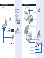
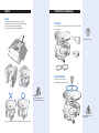
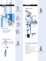
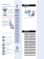
user’s guide
Plug and play
No installation costs
Portable
Compact design
Multi satellite searching
Error-free
Auto positioning capability
Multi auto-searching / Adjustable LNB skew angle
Regional elevation angle selection touch switch
Program update port
Working status on LCD / Built-in compass
Portable Auto Positioning Satellite Antenna
PAPSA
Introduction
User’s Guide
Congratulations’ on purchasing your new PAPSA unit. The PAPSA
is state of the art antenna technology. This user guide contains all
the information required for setup and operation of the PAPSA unit.
Please follow the user guide carefully.
System Diagram
Components
PAPSA Serial Number
This serial number will be
required for all troubleshooting
or service calls made
regarding this product.
WARNING: TO REDUCE RISK OF FIRE
OR ELECTRICAL SHOCK,
DO NOT EXPOSE TO RAIN OR MOISTURE.
A helpful tip that either directs you to a
related area whithin the manual or offers
suggestions on getting the highest quality
out of your system.
An alert to important information regarding
procedures, product specifications, or
product use.
An electrical safety warning to help identify
electrical issues that can be a hazard to
either this SATMARK product or a user.
Information about installation, maintenance,
troubleshooting, or other mechanical issues.
Open
Contents / Assembling
Installing
Watching TV
DATA Update
Specification
Causes and Remedies for
Common Operational Issues
SATMARK Industries Limited Warranty
System Diagram
Components
Feature
PAPSA is plug and play and will automatically search satellite signal.
PAPSA can be located inside dwelling or outside.
Auto Positioning
Antenna dish
Auto-Positioning seeks Satellite
optimum signal
No user interface required.
Sub reflector
Please remember the name
of components.
Horn antenna
LNB skew
controller
LNB case
Reset switch
Control panel
Caution!
Connect to satellite set top box
Do not touch antenna during
automatic setup.
Connections!
Compass
Data cable to PC for data update and download
Power supply
SMPS
AC
24V
100~240V
Foot
Leg
STB-1:Connect to set top box
STB-2 :Connect to set top box
DC :Connect to power supply
POWER :System on/off
DATA :Program update port
* Set top box must be connected to STB-1 port
Check all connections
before operation to avoid
problems.
Open
Contents/ Assembling
Open
Remove tape from packaging (Do not use knife)
packaging contains user manual. Please read carefully
Remove antenna gently from packaging
Remove antenna parts from packaging foam
Contents
User manual, antenna body, antenna horn,4 legs, power cable,
power supply.
Check contents carefully.
Horn Assembly
Insert Horn screw clockwise
by hand gently screw down till firm.
Caution
Do not handle antenna dish
May cause antenna damage.
After assembly do not move
antenna by hand.
Do not handle antenna “dish” Hold antenna by leg or body “only”
Installation
Watching TV
Power/Connect to TV
Installation is possible where there
is clear line of sight facing north.
Avoid placement near
excessive moisture.
After connecting cables
turn power switch on
Terrace or similar location
Roof or similar place
Coax cable
Antenna Location
Place antenna with unobstructed line of sight (sky).
Avoid placement near excessive moisture.
Antenna may be placed on stand.
Set-Top box
SMPS
Stand or similar
AC
24V 100~240V
Remote
controler
TV
Setting Antenna Direction
Move antenna body until
compass direction to target
satellite aligns with triangle.
Check Satellite operation/watching TV
When adjusting position handle
only body or legs.
Turn on TV and set-top box
Power on PAPSA
Wait until antenna searching and positioning is completed
(approx 1 minute)
After antenna positioning is complete PAPSA will start
automatically and TV can now be viewed
If no TV picture check all conditions set-top box PAPSA and TV
Follow the above steps again
Refer to users guide.
If you use single output set
top box always connect to STB-1.
Elevation Angle Setting
DATA Update
A few seconds after System Power On, “satellite name” will appear
elevation angle set menu.
future work
Satellite name
Elevation angles are set
from 35 degree to 70
degrees. User’s can
also choose elevation
angle by location name.
Use up and down switch to choose your location and
push set switch. All settings are finished. Now push
start switch and system will start searching satellite
signals.
Factory setting will be 50 degrees.
After the first settings have been
activated they will be automatically
memorised. There is no need to
reset as long as you remain in the
same location.
LCD window shows current status of auto searching system
H POL.
SELECTED
18V from set top box (Vertical signal)
V POL.
SELECTED
13V from set top box (Horizontal signal)
Only applicable for the above two cases (Linear signal)
CHECK.
STB CBL.
Not connected with set top box- Check
cable connected with STB-1
SIGNAL
DETECTED
Satellite signal found
NIT
DETECTED
Confirm the signal is right information from target
satellite
SIGNAL
LOST.
Cannot find satellite signals - check antenna
direction
Elevation Angle
/ Location name
Use up and down switch
to set locations.
Example(Australia)
↓↑
EL 70DEG
COOKTOWN
↓↑
EL 65DEG
TOWNSVIL
↓↑
EL 60DEG
BRISBANE
↓↑
EL 55DEG
DARWIN
↓↑
EL 50DEG
SYDNEY
↓↑
EL 45DEG
MELBOURN
↓↑
EL 40DEG
HOBART
↓↑
EL 35DEG
PERTH
After antenna is locked in with
satellite you may power off to
save unnecessary power usage.
Data cable to PC for data update or download.
Specification
Antenna Type
Input Frequency
Output Frequency
Antenna Gain
Antenna Size
Polarization
Cross Polarization
LNB Noise Figure
L/O Frequency
Output Impedance
Az Controll Range
EL Controll Range
Power Supply
Operation Temperature
Storage Temperature
Humidity
Weight
Dimension
Parabolic 46 cm
10.7-12.75 GHz
950-2,050 Mhz
33[dBi] / 35[dBi]
460mm / 600mm
Horizontal / Vertical or RHCP / LHCP
〈 -20dB min.
0.9dB max.
Suitable for most frequency ranges world wide
75[Ohm]
360° ±10°
25∼80°
AC100-240[V] / DC24[V]
-30℃∼80℃
-40℃∼85℃
95%@40degrees
7kg
460 x 460 x 410mm
Satellite Signal Blocked
Causes and Remedies for
Common Operational Issues
Satellite signals can be blocked or degraded by buildings,
other vessels, or equipment on the vessel itself. Simply
moving the vessel or obstruction will clear the signal.
There are a number of common issues that can affect the
signal reception quality or the operation of the PAPSA.
The following sections address these issues and potential
solutions.
Blown Fuse, Low Power, or Wiring
If the antenna unit is installed but entirely non-responsive,
there are three key factors to check as part of the troubleshooting process:
Blown Fuse
With the system powered on, move the antenna reflector
slowly by hand. If the reflector does not move freely, a fuse
is not the problem. If the reflector does move freely, one of
the two fuses mounted on the CPU Board may have blown
or been broken. The PAPSA Technical Manual provides
detailed instructions for authorized service personnel who
may be required to replace a fuse. Contact your local
SATMARK dealer or service center for assistance.
Low Power
If the power cable to the antenna unit is more than 50ft
(15 m), the power levels can decrease over the course of
the cable, resulting in a voltage or current level at the
antenna unit that is too low to power the system properly.
The PAPSA Technical Manual provides detailed instructions
for supplying adequate power to the antenna unit.
Contact your local SATMARK dealer or service center for
assistance.
Satellite Coverage Issue
If you need help troubleshooting
your system, Please contact an
authorized SATMARK dealer.
To find an authorized dealer near
you, visit www.satmark.com, or
contact SATMARK directly at the
numbers provided on the first
page of this manual.
PAPSA will provide outstanding reception within the 18”
(45 cm) antenna coverage area for your satellite television
service of choice.
However, reception can be degraded as you approach
the fringe coverage areas.
Refer to your satellite television service manual to check
the viable coverage area for a18” (45 cm) antenna.
Radar Interference
The energy levels radiated by radar units can overload
the antenna’s front-end circuits. Check with your installer
to make certain that the PAPSA antenna unit is in the
optimal location with regard to your radar unit.
Satellite Frequency Data Changed
If some channels work while one or more other channels
do not, or if the antenna is unable to find the satellite, the
selected satellite’s frequency data may have changed.
This frequency data can be updated via the maintenance
port. Contact your local SATMARK dealer or service
center for assistance.
Wiring
If the system has been improperly wired, it will not operate
correctly. The PAPSA Technical Manual provides detailed
instructions for authorized service personnel who may be
required to check the wiring. Contact your local SATMARK
dealer or service center for assistance.
Incorrect or Loose RF Connectors
A loose RF connector can reduce the quality of the
satellite signal.
Also, if you cannot switch satellites using your IRD remote,
your IRD may be connected to the wrong antenna base
plate connector. The PAPSA Technical Manual provides
instructions for authorized service personnel who may
need to check the RF connections.
Contact your local SATMARK dealer or service center for
assistance.
For your convenience, SATMARK
provides links to several web
sites that offer satellite coverage
information. Simply go to our
website at www.satmark.com