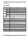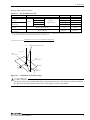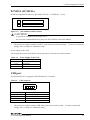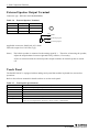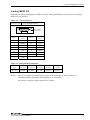
1
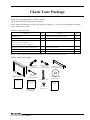
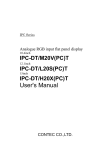
IPC Series
PANEL-PC with .NET4.2 SH-4
20 Series
Hardware Manual
CONTEC CO.,LTD.
Check Your Package
Thank you for purchasing the CONTEC product.
The product consists of the items listed below.
Check, with the following list, that your package is complete.
items, contact your retailer.
If you discover damaged or missing
Product Configuration List
Names
Pcs.
Names
Pcs.
PANECON PC
1
Attaching cover for the main body
1
PCMCIA card removal prevention fittings
1
CONTEC SDK for CE420
1
Screws for attaching the PCMCIA card
1
EU Declaration of Conformity
1
AC power cable removal prevention clamp
1
IPC Precaution List
1
USB cable removal prevention clamp
1
Product guide
1
AC power cable
1
removal prevention fittings
Three-point sems screw
(Notes)
(M3 x 6)
User’s manual is not bundled with this product ; it must be prepared by the user.
Product Configuration Image
PCMCIA card
AC power cable
removal
removal
prevention fittings prevention clamp
PANECON PC
IPC
Precaution List
IPC Precaution List
USB cable
removal
prevention clamp
Attaching cover
for the main body
CONTEC SDK
for CE420
AC power cable
EU Declaration
of Conformity
EU Declaration
of Conformity
PC-PT020 Hardware Manual
Product
guide
Three-point
sems screw
Product guide
i
Copyright
Copyright 2007 CONTEC CO., LTD.
ALL RIGHTS RESERVED.
No part of this document may be copied or reproduced in any form by any means without prior written
consent of CONTEC CO., LTD.
CONTEC CO., LTD. makes no commitment to update or keep current the information contained in this
document.
The information in this document is subject to change without notice.
All relevant issues have been considered in the preparation of this document. Should you notice an
omission or any questionable item in this document, please feel free to notify CONTEC CO., LTD.
Regardless of the foregoing statement, CONTEC assumes no responsibility for any errors that may
appear in this document or for results obtained by the user as a result of using this product.
Trademarks
Intel and Celeron are registered trademarks of Intel Corporation. MS, Microsoft and Windows are
trademarks of Microsoft Corporation. Other brand and product names are trademarks of their
respective holder.
ii
PC-PT020 Hardware Manual
Table of Contents
Check Your Package ................................................................................................................................ i
Copyright.................................................................................................................................................ii
Trademarks ..............................................................................................................................................ii
Table of Contents ...................................................................................................................................iii
1
BEFORE USING THE PRODUCT
1
About the Product ................................................................................................................................... 1
Features ............................................................................................................................................ 1
Customer Support.................................................................................................................................... 2
Web Site ........................................................................................................................................... 2
Limited One-Year Warranty ................................................................................................................... 2
How to Obtain Service............................................................................................................................ 2
Liability ................................................................................................................................................... 2
Safety Precautions................................................................................................................................... 3
Safety Information ........................................................................................................................... 3
Handling Precautions ....................................................................................................................... 3
2
OVERVIEW
7
Specifications .......................................................................................................................................... 7
External Dimensions ............................................................................................................................. 10
3
EACH COMPONENT FUNCTION
11
Component Locations ........................................................................................................................... 11
Component Identification ..................................................................................................................... 13
Serial Port Interface (COM1, COM2)........................................................................................... 13
Ethernet (LAN) .............................................................................................................................. 14
PCMCIA (PCMCIA) ..................................................................................................................... 15
USB port......................................................................................................................................... 15
External Speaker Output Terminal................................................................................................ 16
Touch Panel.................................................................................................................................... 16
Analog RGB I/F ............................................................................................................................. 17
4
HARDWARE SETUP
19
Hardware Setup ..................................................................................................................................... 19
Installation Requirements .............................................................................................................. 20
Attaching the cover for this product.............................................................................................. 21
Attaching the PCMCIA card removal prevention fittings............................................................ 22
Back light exchange....................................................................................................................... 22
Attaching the USB cable removal prevention clamps.................................................................. 23
PC-PT020 Hardware Manual
iii
Attaching the AC cable removal prevention clamps.....................................................................25
Attaching to the VESA Arm ..........................................................................................................27
5
iv
LIST OF OPTIONS
29
PC-PT020 Hardware Manual
1. Before Using the Product
1 Before Using the Product
About the Product
This product is a panel computer based on Windows CE NET 4.2, which has an excellent
dustproof/drip-proof structure. It uses SH-4 with 128MB of memory as its CPU.
The touch panel has an analog resistive glass/glass-style screen with excellent durability. The frame is
made of rust resistant stainless steel as well as in an IPX2-rated drip-proof structure. The front side
has an IP65-rated dustproof and drip-proof structure. This product comes with various expansion
interfaces such as USB, PC card, 100BASE-T and RS-232C interfaces. In addition, the product can be
mounted on an LCD arm, as it complies with the VESA standard.
Features
SH-4-type CPU with 128MB of memory and rewritable/erasable 128MB Flash ROM
This product comes with SH-4(CPU), 128MB of memory and Windows CE NET4.2 (OS). It also has
a 128MB Flash ROM, which can be used as a user area and allow the user to write and erase user
programs.
Whole frame in IPX2-rated drip-proof structure; front side in IP65-rated dustproof/drip-proof structure
The whole frame is IPX2-rated and waterdrop-proof. The front side is in an IP65-rated structure that
protects against dust and streams of water. For the touch panel, an analog resistive glass/glass-style
film with excellent durability has been adopted.
Rust-resistant stainless steel used for the cabinet
For the frame, rust-resistant stainless steel has been adopted with a protection cover that protects the
interfaces against waterdrops.
Expansion interfaces such as USB and PC card for PC standard
This product has two USB ports, a PC card slot (Type II x 2, or Type III x 1), 100BASE-T x 1,
RS-232C x 2, analog RGB and stereo sound functions. The main frame has small built-in speakers,
which allow you to switch to external speakers. The analog RGB interface supports dual screen
display. This product also comes with the drivers required for the built-in interfaces as standard
equipment.
XIP-ROM module enabling high-speed startup as fast as approx. 10 seconds
As the OS image is pre-loaded in the XIP-ROM, the OS can start as fast as about 10 seconds after
power-up.
Mounting structure supporting VESA 100mm standard
Mounting structure supporting the VESA 100mm standard allows you to install this product on an LCD
arm.
System development support tool “CONTEC Manager” provided
This product comes with “CONTEC Manager”, which helps you build a range of systems such as FTP
server function, scheduling function, NTP-based automatic time adjustment function and Auto-RUN
function.
PC-PT020 Hardware Manual
1
1. Before Using the Product
Customer Support
CONTEC provides the following support services for you to use CONTEC products more efficiently
and comfortably.
Web Site
Japanese
English
Chinese
http://www.contec.co.jp/
http://www.contec.com/
http://www.contec.com.cn/
Latest product information
CONTEC provides up-to-date information on products.
CONTEC also provides product manuals and various technical documents in the PDF.
Free download
You can download updated driver software and differential files as well as sample programs available in
several languages.
Note!
For product information
Contact your retailer if you have any technical question about a CONTEC product or need its price,
delivery time, or estimate information.
Limited One-Year Warranty
CONTEC products are warranted by CONTEC CO., LTD. to be free from defects in material and
workmanship for up to one year from the date of purchase by the original purchaser.
Repair will be free of charge only when this device is returned freight prepaid with a copy of the
original invoice and a Return Merchandise Authorization to the distributor or the CONTEC group office,
from which it was purchased.
This warranty is not applicable for scratches or normal wear, but only for the electronic circuitry and
original products. The warranty is not applicable if the device has been tampered with or damaged
through abuse, mistreatment, neglect, or unreasonable use, or if the original invoice is not included, in
which case repairs will be considered beyond the warranty policy.
How to Obtain Service
For replacement or repair, return the device freight prepaid, with a copy of the original invoice. Please
obtain a Return Merchandise Authorization number (RMA) from the CONTEC group office where you
purchased before returning any product.
*
No product will be accepted by the CONTEC group without the RMA number.
Liability
The obligation of the warrantor is solely to repair or replace the product. In no event will the
warrantor be liable for any incidental or consequential damages due to such defect or consequences that
arise from Safety Precautions.
Understand the following definitions and precautions to use the product safely.
2
PC-PT020 Hardware Manual
1. Before Using the Product
Safety Precautions
Understand the following definitions and precautions to use the product safely.
Safety Information
This document provides safety information using the following symbols to prevent accidents resulting
in injury or death and the destruction of equipment and resources. Understand the meanings of these
labels to operate the equipment safely.
DANGER
DANGER indicates an imminently hazardous situation which, if not avoided, will
result in death or serious injury.
WARNING
WARNING indicates a potentially hazardous situation which, if not avoided, could
result in death or serious injury.
CAUTION
CAUTION indicates a potentially hazardous situation which, if not avoided, may
result in minor or moderate injury or in property damage.
Handling Precautions
WARNING
-
Do not use this product in the presence of flammable or corrosive gases.
explosion, fire, or damage to equipment.
-
In the event of smoke, or abnormal smells or sounds, immediately turn OFF the power to this
device, disconnect the plug from the power outlet, and contact the manufacturer. Continued use
could lead to fire or electrical shock.
-
Because of the danger of electrical shock or fire, do not contact this device (Other than the front
touch panel) while electrical current is present.
-
Never touch this device or connectors with wet hands.
-
Do not allow this device to come into contact with foreign substances (metal particles, flammable
substances, liquids, etc.). This can cause fire or electrical shock.
-
Do not place this device in an unstable location or use incomplete mountings.
device to fall.
-
This device must be operated at the specified voltage.
fire or electrical shock.
-
This device must be properly grounded.
-
Users should never disassemble or modify this device, or exchange components. This can cause
fire or electrical shock. In addition, the manufacturer is unable to repair products that have been
modified by the user.
-
Procedures that could result in serious injury or loss of human life should never be performed from
a touch panel. Use system design methods that can guard against input errors.
PC-PT020 Hardware Manual
This may lead to
This can cause electrical shock.
This may cause the
Use of any other voltage level may cause
3
1. Before Using the Product
CAUTION
-
Do not use or store the product in a location such as extremely high or low temperature,
temperature changes, and the place which receives a strong ultraviolet ray.
Example: - Exposure to direct sun
- In the vicinity of a heat source
rapid
-
Do not use the product in extremely humid or dusty locations.
It is extremely dangerous to use the product with its interior penetrated by water or any other fluid
or conductive dust. If the product must be used in such an environment, install it on a dust-proof
control panel, for example.
-
Avoid using or storing the device in locations subject to shock or vibration.
-
Do not use the product in the vicinity of devices that generate strong magnetic force or noise.
Such devices will cause this device to malfunction.
-
Do not use or store the product in the presence of chemicals.
-
To clean the PANECON-PC, wipe it gently with a soft cloth dampened with either water or mild
detergent. Do not use chemicals or a volatile solvent, such as benzene or thinner, to prevent
pealing or discoloration of the paint.
-
Do not use any sharp-pointed object such as a mechanical pencil to touch the touch panel.
so may scratch the touch panel, resulting in malfunctions.
-
Do not subject the touch panel to shock as doing so may break it.
-
When the surface or frame of the touch panel has become dirty, wipe it with neutral detergent. Do
not wipe the touch panel with thinner, alcohol, ammonia, or a strong chlorinated solvent. Use a
protective sheet (available as an option) if the touch panel is used where it can easily collect dust
and dirt.
-
The touch panel may be damaged, if adhesive tape is applied and then peeled off its surface.
Doing
-
The touch panel may be damaged, if a suction cup is applied and peeled off its surface.
-
Do not use a cutter or steel wool to scrape foreign matter off the touch panel.
Also, do not clean the touch panel with dry waste.
-
Do not clean the touch panel with the waste which has been soaked in a strong chemical or
detergent (e.g. acetone, xylene, toluene, general thinner, ketone solvent, acidic/alkaline chemicals
and detergents, abrasive chemicals and detergents), or it may result in a stain or malfunction.
-
When cleaning the touch panel, soak soft waste in water, squeeze it firmly, and use it on the surface
in a lightly rubbing motion. Do not clean the touch panel with saturated material. (It is
recommended to dry it immediately after cleaning.)
-
Use waste dedicated for cleaning lenses (e.g. lens cloth) to clean the touch panel in a lightly rubbing
motion.
-
It is a characteristic of analog touch panels that their resistance may vary with changes to the
ambient environment (temperature and humidity) and with their own aging, resulting in the
deviation of the detection point. If this is the case, calibrate the touch panel again to re-set
calibration data.
4
PC-PT020 Hardware Manual
1. Before Using the Product
-
-
-
-
Burn-in on TFT Display
"Burn-in" may occur if the same display is retained for a long time. Avoid this by periodically
switching the display so that the same display is not maintained for a long time.
* Burn-In : Phenomenon characterized by a TFT display as a result of long-time display of the
same screen where a shadow-like trace persists because electric charge remains in the
LCD element even after the patterns are changed.
Life expectancy of components
(1) Battery
:
A lithium-ion primary battery is used to back up the internal
clock/calendar and CMOS RAM. The non-energized backup time at
25°C is 10 years or more and at 60°C is 7 years or more.
(2) LCD backlight
:
Display brightness decreases over time with use.
The operating lifetime of the backlight is 50,000 hours (the time until
the brightness is lowered to 50% of the initial value)
(3) Touch panel
:
The operating lifetime of the touch panel is at least 1 million touches (as
tested by mechanical touching under 1N of force at a rate of five presses
per second).
(4) Power supply
:
The expected battery life is 5 years in continuous operation at 40°C.
However, the battery will not last as long, if used at a temperature
exceeding the operating temperature limit.
(5) Flash memory (NFDISK) : The number of times of rewriting has restriction that is more
than 1,000,000. (When the write size is 128KB or less.)
Since CF-CARD is used for Flash memory (NFDISK), When
use is carried out for the use that rewrites frequently, be careful
of the number of times of rewriting.
Moreover, when power supply OFF is done while writing it, data
in flash memory (NFDISK) might be damaged.
* CONTEC accepts your request for replacing each consumable in the PANECON-PC as a request
for repair (at an additional cost).
Be sure to turn off the power before plugging or unplugging any expansion board or connector.
CONTEC reserves the right to refuse to service a product modified by the user.
In the event of an abnormal condition or malfunction, please consult your retailer.
Use an AC cable that is compatible with both the rated supply voltage and the receptacle.
To connect with peripherals, use a grounded, shielded cable.
This product contains a lithium battery as the primary cell and a cold cathode tube for the backlight.
When disposing of the product, therefore, treat it in accordance with the disposal regulations
stipulated by your local government.
About VCCI class A, FCC PART15 class A, and EMC instruction class A incidental articles
This product acquires the above-mentioned standard, and when an external speaker is used, an
enough margin might not be able to be secured. In that case, please install the ferrite core (SEIWA
E04SR200935A or interchangeable goods) in the speaker connection cable. Please shut after it
wraps it twice near the connector with the ferrite core opened when you install it.
PC-PT020 Hardware Manual
5
1. Before Using the Product
FCC PART 15 Class A Notice
NOTE
This equipment has been tested and found to comply with the limits for a Class A digital device,
pursuant to part 15 of the FCC Rules. These limits are designed to provide reasonable protection
against harmful interference when the equipment is operated in commercial environment.
This equipment generates, uses, and can radiate radio frequency energy and, if not installed and
used in accordance with the instruction manual, may cause harmful interference to radio
communications. Operation of this equipment in a residential area is likely to cause harmful
interference at his own expense.
WARNING TO USER
Change or modifications not expressly approved the manufacturer can void the user's authority to
operate this equipment.
6
PC-PT020 Hardware Manual
2. Overview
2 Overview
Specifications
Functional Specifications
Table 2.1. Functional Specifications
Type
LCD type
LCD type
Touch panel
Resolution
IPC-PT020LS-AC-4E
12.1-inch TFT color LCD (800 x 600)
Number of colors 65536
4096 x 4096 (emulated in 800 x 600 mode)
Detection method Resistive-film analog glass/glass type
CPU
Memory
COM port
Type
SH-4, HD6417751RBP
Internal cache
Data: 16KB, Instruction: 32KB
Clock frequency
240MHz
Flash memory
(NFDISK)
128MB
System memory
128MB
OS loading
Flash memory
32MB
RS-232C(2ch)
COM1 (16550, 9-pin D-SUB)
COM2 (16550, 9-pin D-SUB)
Baud rate : 50 - 115200bps
SDRAM
RTC
The real-time clock is accurate within ±1 minutes (at 25ºC) per month
DALLAS CO., LTD. DS12887A
LAN
10BASE-T/100 BASE-TX 1ch, NS CO., LTD. DP83816A
PC card slots
PCMCIA Type II x 2 or Type III x 1
General-purpose I/O
None
USB
2ch (USB 1.1)
Output terminals for external
speakers
φ3.5 Stereo mini jack Full-scale output level 1.0Vrms (Typ.)
Built-in speaker
Rated input 0.3W
Connected to analog (L) signal of stereo output
External RGB output
Analog RGB output 15-pin HD-SUB (Female) connector
DIP-SW
None
LED
None
Front function switch
Front switch input : 3 points
Front PowerLED
3-color display
Input power supply
100VAC
Input range: 100V - 240VAC
Power consumption
100VAC input type: 50VA (Max.)
External dimensions (mm)
303(W) x 56.5(D) x 246(H)
Panel cut dimensions (mm)
None
Weight
About 3.6kg *1
*1
50VA
Includes the attachments except cables.
PC-PT020 Hardware Manual
7
2. Overview
Installation Environment Requirements
Table 2.2.
Installation Environment Requirements
Item
Specification
Ambient specifications
Operating temperature
0 - 45ºC *1
Storage temperature
-10 - 60ºC
Operating Humidity
20 - 85%RH (No condensation)
Floating dust particles
Not to be excessive
Corrosive gases
Line noise
Line-noise
resistance
Static
electricity
resistance
None
AC line: 2kV
Signal line: 1kV (EN61000-4-4 Level3, IEC1000-4-4 Level 3)
Contact discharge / ±4kV (EN61000-4-2 Level 2, IEC1000-4-2 Level 2)
Atmospheric discharge / ±8kV (EN61000-4-2 Level 3, IEC1000-4-2 Level 3)
Anti-shaking 10 - 57Hz/semi-amplitude 0.075mm
One cycle (10-150-10 Hz) of 1oct/min test at 9.8 m/s2 (1G) between 57 an
150 Hz x 5 times in three (X/Y/Z) directions (40 minutes each)
(JIS C0040-compliant, IEC68-2-6-compliant)
Vibration
resistance
Impact resistance
Tested with 11-ms half-sine wave at 98 m/s2 (10G) three times in each of
three (X/Y/Z) directions
(JIS C0041-compliant, IEC68-2-27-compliant)
Ground
Class D grounding (previous class 3 grounding) SG-FG/continuity
Water-proof and dust-proof Whole frame : IPX2-compatible (in normal installation), Screen : IP65 *2
*1 When the total supply current of the USB connector exceeds 200mA, the Operating temperature of use becomes
0-40 ºC.
Attaching cover for the main body.
*2 Please obtain the Attaching cover for the main body of appending to Water-proof and dustproof.
Table 2.3.
Power Installation Environment Requirements
Item
Specification
Power specifications
Allowable instantaneous
17ms or less (ACIN100V, Io=100%, average value)
Voltage resistance
AC2.0kV (between input and FG) 10mA 1 minute
Isolated resister
50MΩ (500VDC)
IP Protection Ratings
IP Protection Ratings indicate levels of protection against intrusion by solid foreign substances and
water.
-
IP65 … This product does not allow entry of dust into it. It also does not allow entry of water
from any direction, even when directly squirted on with a strong pressure.
-
IPX2 … The product is not badly affected by water dropped vertically from the top or within an
angle of 15 degrees.
8
PC-PT020 Hardware Manual
2. Overview
Display Optical Specifications
Table 2.4.
IPC-PT020LS-AC-4E
Parameter
Condition
φ = 180°
View angle
(Vertical)
CR⊇5
View angle
(Horizontal)
φ = 0°
φ = +90°
Display.
Monochrome
Brightness
(at center) *1
35deg
45deg
55deg
70deg
70deg
60deg
70deg
Display. Monochrome
100
None
Display. White
280cd/m2
350cd/m2
*1 The surface brightness is a numerical value in the display unit.
becomes the above-mentioned numerical value of about 84%.
Contrast ratio (CR) =
Typ.
60deg
φ= -90°
Contrast
Min.
Brightness by which the touch panel is passed
Brightness at screen center with white displayed
Brightness at screen center with black displayed
Measurement direction
Z
( θ = 0o )
Left
( φ = -90o )
θ
Top
( φ = 180o )
φ
X
Module
Bottom
( φ = 0o )
Right
( φ = 90o )
Y
Figure 2.1.
Definition of viewable range
CAUTION
The above optical specification data shows optical characteristics of the liquid crystal in the display;
the data does not represent the actual view on the display or its viewing angles.
PC-PT020 Hardware Manual
9
2. Overview
Physical Dimensions
IPC-PT020LS-AC-4E
303
4-M4 TAP
(Maximum tapping length: 5mm)
56.5
246
21.5
100
100
AC - IN
V GA
CO M2
CO M1
L AN
LNK
ACT
U SB
R ST
SP K
PCMCIA
53.5
POW E R
SW
CONTEC
VCCI-A
Dust cover (bundled)
32.6
[mm]
Figure 2.2.
10
Physical Dimensions
PC-PT020 Hardware Manual
3. Each Component Function
3 Each Component Function
Component Locations
Interface
The lower side of the back
POWER
SW
AC - IN
VGA
COM2
COM1
LAN
LNK
ACT
USB
RST
SPK
PCMCIA
Bottom side
POWER
SW AC-IN
VGA
COM2
COM1 LAN USB RST
SPK
PCMCIA
Front side
Function switch
Figure 3.1.
POWER LED
Component Locations
PC-PT020 Hardware Manual
11
3. Each Component Function
Table 3.1.
Component Identification
Component
POWER SW
Function
Power switch
AC-IN
AC in-let cable connection
VGA
Analog RGB I/F
COM1
Serial port 1
COM2
Serial port 2
PCMCIA
PCMCIA card slot
LAN
Ethernet connector (RJ-45)
USB
USB port connector
RST
Hard reset push button
SPK
Output terminals for external speakers
PCMCIA
,
,
POWER LED
12
PCMCIA card slot
Function switch
Power ON display LED
PC-PT020 Hardware Manual
3. Each Component Function
Component Identification
Serial Port Interface (COM1, COM2)
The PANECON-PC is equipped with two RS-232C-compliant serial port connectors (Serial Port 1:
COM1 and Serial Port : COM2). Baud rate : 50 - 115200bps
Table 3.2.
COM1/COM2 Serial Port Inter Connector
Main unit connector
D-SUB 9-pin(Male)
1
5
No.4-40UNC
Inch screw
6
9
Pin No.
Signal
Function
Direction
1
CD
Carrier detection
In
2
RD
Recieved data
In
3
TD
Transmitted data
Out
4
DTR
Data terminal ready
Out
5
GND
Signal ground
-----
6
DSR
Data set ready
In
7
RTS
Request to send
Out
8
CTS
Clear to send
In
9
RI
Ring indicator
In
PC-PT020 Hardware Manual
13
3. Each Component Function
Ethernet (LAN)
Table 3.3.
Ethernet connector (RJ-45)
Connector type
RJ-45
1
LINK
8
ACT
Pin No.
Singal name
Function
1
TX+
Transmitted data (+) output
2
TX-
Transmitted data (-) output
3
RX+
Received data (+) input
4
N.C.
Not connected
5
N.C.
Not connected
6
RX-
Received data (-) input
7
N.C.
Not connected
8
N.C.
Not connected
LED indicator
-
LINK(Green)
Indicates the LINK status.
-
ACT(Orange)
Indicates that data is being transmitted/received when flashing.
14
PC-PT020 Hardware Manual
3. Each Component Function
PCMCIA (PCMCIA)
PCMCIA compliant card slots are provided [TYPE II x 2 (TYPE III x 1) size].
Slot 1
Slot 2
Figure 3.2.
Slot Numbers and Locations
CAUTION
- A type III card should be inserted into slot 2.
- In case of the CompactFlash Card, please use the PCMCIA conversion adapter.
*
This product is bundled with the PCMCIA card removal prevention fittings.
fittings, refer to Chapter 4 “Hardware Setup”.
For how to mount the
Power Supply to the Card
The voltage that can be used and the current capacity of each slot are as shown below:
Table 3.4.
Power Supply to the Card
Voltage
Current capacity (Max.)
+5V
250mA/Slot
+3.3V
250mA/Slot
+12V
Not supplied.
USB port
The PANECON-PC is equipped with USB interface 2 channels.
Table3.5.
USB connector
1
Pin No.
*
4
Signal name
1
+5V
2
DATA+
3
DATA-
4
GND
This product is bundled with the USB cable removal prevention cramp.
fittings, refer to Chapter 4 “Hardware Setup”.
PC-PT020 Hardware Manual
For how to mount the
15
3. Each Component Function
External Speaker Output Terminal
Connector type : HSJ1456-010320(HOSIDEN)
Table 3.6.
External Speaker Terminal
Remarks
Pin No.
Signal
1
GND
---
2
Analog signal (R)
Speaker (Right)
3
Analog signal (L)
Speaker (Left)
1pin
2pin
3pin
GND
R Analog signal
L Analog signal
Applicable connector: Small jack of φ3.5mm
Full-scale output level 1.0Vrms (Typ.)
Notes)
The built-in speaker is connected to the analog signal (L). Therefore, when using the speaker,
adjust the output balance between right and left by software, if necessary.
If Jack is connected with the external speaker output terminal, an internal speaker is turned
off.
Touch Panel
The PANECON-PC is equipped with an analog touch panel that enables keyboard-less, mouse-less
operations.
Refer to the software manual for details on how to use the touch panel.
Table 3.7.
Touch panel specifications
Model
This product
Detection method
Analog resistive glass / glass type
Active area
249.0 x 187.5mm
Surface treatment
No glare
Resolution
4096 x 4096 (emulated in 800 x 600)
Operating load
Min.0.2N, Max.3N (1N=0.102kgf)
Operating lifetime
1 million touches minimum
(Load : 1N, 5 sec/application, Tip shape : silicon rubber, φ10mmR125)
16
PC-PT020 Hardware Manual
3. Each Component Function
Analog RGB I/F
Simultaneous dual screen display is enabled, when an analog RGB display is connected to the Analog
RGB I/F of this product.
Table 3.8.
VGA connector
Connector type
15-pin HD-SUB (Female)
1
5
10
6
No.4-40UNC
Inch screw
15
Pin No.
11
Signal
name
Pin No.
Signal
name
1
RED
9
VCC
2
GREEN
10
GND
3
BLUE
11
N.C.
4
N.C.
12
N.C.
5
GND
13
HSYNC
6
GND
14
VSYNC
7
GND
15
N.C.
8
GND
Table 3.9. Analog RGB specifications
Display
Dots
Dot Clock
Frequency
Horizontal
Frequency
Vertical
Frequency
HSYNC
Polarity
VSYNC
Polarity
800 x 600
40.0MHz
37.9KHz
60.1Hz
Negative
Negative
Notes)
The use of a liquid crystal display may cause disturbed images on the screen due to a
resolution problem, depending on the display to be connected.
The display resolution is 800 x 600(SVGA) fixation.
PC-PT020 Hardware Manual
17
3. Each Component Function
18
PC-PT020 Hardware Manual
4. Hardware Setup
4 Hardware Setup
Hardware Setup
-
Make sure that the power is switched off before you start the operation.
-
Do not remove any screws other than those explained here.
-
As for the following items, be sure to setup.
1.
Attaching cover for the main body
2.
Attaching the USB cable removal prevention clamps
3.
Attaching the AC cable removal prevention clamps
4.
Attaching the PCMCIA card removal prevention fittings
PC-PT020 Hardware Manual
19
4. Hardware Setup
Installation Requirements
50
50
50
When installing this product vertically, place the interface block at the bottom. To maintain the
ambient temperature within the installation environment requirement range, provide a gap of 50mm or
more between the main unit and any adjacent equipment.
Also, use the product within an angle of 60 degrees, as shown in the following figure.
50
50
50
50
50
[mm]
Figure 4.1.
15°
Distances between the PANECON-PC and Its Vicinity
60°
Figure 4.2. Installation permitted angle of the main body
20
PC-PT020 Hardware Manual
4. Hardware Setup
Attaching the cover for this product
1.
Loosen the screws of the main body, as shown in the following figure.
Figure 4.3. Attaching cover for the main body
2.
<1/2>
Mount the bundled attaching cover for the main body by tightening the screws back, ensuring that
the cover contacts the body without any gap at the positions specified in the following figure.
Figure 4.3. Attaching cover for the main body
PC-PT020 Hardware Manual
<2/2>
21
4. Hardware Setup
Attaching the PCMCIA card removal prevention fittings
1.
2.
Insert the PCMCIA card.
Hook the right catch of the fittings on the narrow square hole of the main body, as shown in the
following figure, and push it in so that the PCMCIA card is covered.
Figure 4.4. Attaching the PCMCIA card removal prevention fittings
3. Secure the fittings at the upper end with the provided screw.
<1/2>
Figure 4.4. Attaching the PCMCIA card removal prevention fittings
<2/2>
Back light exchange
The backlight used in the LCD module has a limited life.
contact your retailer.
22
When it expires and requires replacement,
PC-PT020 Hardware Manual
4. Hardware Setup
Attaching the USB cable removal prevention clamps
1.
Connect the USB cable.
Figure 4.5. Attaching the USB cable removal prevention clamps
2.
<1/3>
Tie the USB cables together using the provided clamp for preventing USB cables from being
disconnected.
Figure 4.5. Attaching the USB cable removal prevention clamps
PC-PT020 Hardware Manual
<2/3>
23
4. Hardware Setup
3.
Fix the USB cable removal prevention clamps to the main body as the following diagrams.
Figure 4.5. Attaching the USB cable removal prevention clamps
24
<3/3>
PC-PT020 Hardware Manual
4. Hardware Setup
Attaching the AC cable removal prevention clamps
1.
Fix the AC cable removal prevention clamps.
Figure 4.6. Attaching the AC cable removal prevention clamps
2.
<1/4>
Connect the AC cable.
Figure 4.6. Attaching the AC cable removal prevention clamps
PC-PT020 Hardware Manual
<2/4>
25
4. Hardware Setup
3.
Tie the AC cables together using the AC cable removal prevention clamps from being disconnected.
Then, push in the clamp and secure it firmly, as shown with the arrow in the following figure, so
that the clamp does not move.
Figure 4.6. Attaching the AC cable removal prevention clamps
4.
Be sure that the AC cable is fixed.
Figure 4.6. Attaching the AC cable removal prevention clamps
26
<3/4>
<4/4>
PC-PT020 Hardware Manual
4. Hardware Setup
Attaching to the VESA Arm
This product can be attached to the VESA-standard 100mm arm.
When attaching the VESA arm, note the following item.
-
Load : Select the VESA arm of an enough load to the weight of this product.
-
Installation angle : set it up to install the inclination of the back and forth on installation
requirements.
-
For more details on the attaching method, refer to the VESA arm’s manual.
PC-PT020 Hardware Manual
27
4. Hardware Setup
28
PC-PT020 Hardware Manual
5. List of Options
5 List of Options
Manual
- IPC-PT020LS-HMJ
: Hardware manual for IPC-PT020LS-AC series
(Japanese)
- IPC-SH4CE4-SMJ
- IPC-SH4CE4-SME
: Software manual (Japanese)
: Software manual (English)
Other
- IPC-SND-03
Notes)
: Desk stand
As the desk stand (IPC-SND-03) is not made of stainless steel, care must be taken for its
use environment.
PC-PT020 Hardware Manual
29
IPC-PT020LS-AC-4E
Hardware Manual
IPC-PT020LS-HME
CONTEC CO., LTD.
November 2008 Edition
3-9-31, Himesato, Nishiyodogawa-ku, Osaka 555-0025, Japan
Japanese http://www.contec.co.jp/
English http://www.contec.com/
Chinese http://www.contec.com.cn/
No part of this document may be copied or reproduced in any form by any means without prior written
consent of CONTEC CO., LTD.
[11072008]
[04192007]
[11102008_rev6]
Management No.A-51-387
Parts No.
LYHC356