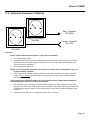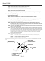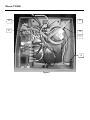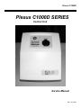
1
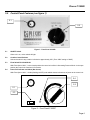
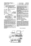
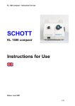
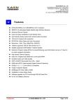
Plexus C/1000D
Plexus C1000D SERIES
Control Unit
Service Manual
PN 11812-000
Plexus C/1000D
Table of Contents
Important
Section
Description
Page
1.0
Contraindications/Indications/Precautions
2
2.0
Receiving Inspection
2
3.0
Repair Policy
2
4.0
Specifications
3
5.0
Control Unit Setup
4
6.0
Cleaning
5
7.0
Rear Panel Features
6
8.0
Routine Maintenance and Function Testing 7
9.0
Function Test Record Sheet
10
10.0
Current Leakage Retrofit
12
11.0
Calibration Procedure
13
12.0
Troubleshooting
14
13.0
Parts List
17
Figures
Figure
Description
1
Front Control Panel
5
2
Rear Panel Features
7
3
Manifold Test
11
4
Mattress Test
11
5
Function Test / Calibration
11
6
Float Style Timing Motor
16
7
Parts D or DE Models
17
8
Parts DF Models
18
7
Valve Assembly, and parts
19
Page 1
Page
Before using the Plexus C1000D please read and
understand the Plexus C1000D Operator’s Manual and
the SAFETY INSTRUCTIONS prior to each application.
Only qualified medical service personnel should repair
the Plexus C1000D.
In the event of any questions, contact our Technical
Service Department for assistance:
USA Only:
Phone
1 800 828-7341
Fax
1 800 993-7890
Outside USA:
Phone
(716) 662 8636
Fax
(716) 662-0730
Plexus C/1000D
1.0
Contraindications
Refer to Operator’s Manual.
1.1
Indications for Use/Theory of
Operation
Refer to Operator’s Manual.
1.2
Safety Precautions
Review the following SAFETY PRECAUTIONS prior
to servicing the Plexus C1000D.
DANGER
•
Explosion hazard. Do not use in the presence of
flammable anesthetics.
• Risk of electric shock. Refer servicing to
qualified service personnel.
WARNING
•
Never drop or insert any object into any opening
of the control unit. Doing so may cause fire or
electrical shock by shorting internal
components.
•
Do not spill food or liquids into the Control Unit.
If spillage does occur, turn off the unit,
disconnect it from its power supply and allow at
least 24 hours for drying.
•
Keep unit away from radiators or other heat
sources.
CAUTION
•
2.0
Do not return the Plexus C1000D Control Unit to
Plexus Medical. Contact Plexus Medical's Technical
Service Department for instructions.
Repairs should be performed only by qualified
personnel familiar with repair practices for
servicing medical devices. Do not attempt to
repair the Plexus C1000D Control Unit unless
you possess these skills. Otherwise, damage to
or malfunction of the control unit may result.
Receiving Inspection
Upon receipt, unpack the Plexus C1000D Control
Unit and inspect for concealed damage. Save all
packing material. If any damage is found, notify the
carrier at once and ask for a written inspection.
Prepare a written description of any damage.
Photograph any damage.
Failure to take the above action within 15 days of receipt
may result in loss of claim.
USA only
Outside USA
3.0
1 800 828-7341
(716) 662-8636
Repair Policy
The Plexus C1000D Control Unit is warranted free of
defects in material and workmanship for a period of two
(2) years.
The Control Unit is warranted under the terms and
conditions of the Plexus Medical warranty in place at the
time of purchase. A copy of the warranty is available
upon request. Plexus Medical disclaims all implied
warranties including, but not limited to, the implied
warranties of merchantability and of fitness for a
particular purpose.
Control units may be returned to the factory for servicing
(see 4.3, Return Authorization).
For customers who choose to repair Plexus C1000D
Control Units at their location, this manual contains
information to allow a qualified technician to make
necessary repairs. For technical support, contact Plexus
Medical's Technical Service Department.
3.1
In-Warranty Repairs
All in-warranty repairs must be authorized by Plexus
Medical's Technical Service Department before
proceeding.
3.2
Out-of-Warranty Repairs
The following repair options are available when servicing
Plexus C1000D Control Units:
1. Defective Components - replacement parts may
be ordered by specifying the Plexus Medical
part number as shown in the parts lists.
2. Plexus C1000D Control Unit Repairs - If the
Plexus C1000D Control Unit becomes
inoperative and the cause cannot be
determined, the complete control unit may be
returned to the factory for servicing at the
purchaser's expense (see 4.3, Return
Authorization).
3.3
Return Authorization
Please be sure to obtain a return goods (RG)
authorization number from Plexus Medical's Customer
Service Department before returning the Plexus C1000D
Control Unit or any component parts to Plexus Medical.
USA only
Outside USA
1 800 828-7341
(716) 662-8636
Page 2
Plexus C/1000D
4.0
Specifications
Physcial
Dimensions
12" x 10 1/4" x 5"
(30.5 cm x 26 cm x 13 cm)
Weight
4.2 to 5 lbs. (1.9 to 2.3 kg)
Operating Ambient
Temperature Range
60°F to 80°F
15.5°C to 26.5°C
Storage and Shipping Conditions
Ambient Temperature
40°F to 105°F Range
4.5°C to 40.5°C
Relative Humidity
10% to 100% Non-condensing
Electrical
C/1000DC1000DE/DFE/CE
Power
Frequency
Current
Fuse
115 VAC
230 VAC
60 Hz
50 Hz
1A
.5A
F 0.15A
F 0.15A
Type BF Equipment
Attention, Consult Accompanying
Documents
IPXO
Page 3
Protection Against Harmful Ingress of
Liquids Ordinar y Protection (IPX0)
Plexus C/1000D
5.0
Control Panel Features (see figure 1)
5.1
5.2
Figure 1 - Front Panel C1000D
5.1
ON/OFF Switch
When unit is on, rocker switch will light.
5.2
Comfort Control Selector
Selector has built in stop, rotation is limited to approximately 320° (From “MIN” setting to “MAX”)
5.3
Float Switch PN 10322-BLAN
With Float Option ONLY - In the closed position the control unit will be in Alternating Pressure Mode. In the open
position the control unit functions in float mode.
5.4
Power Fail Indicator and Alarm (Not shown)
With Float Option ONLY - Visible (flashing red LED) and audible alarms indicate loss of power to the control unit.
5.4
1
0
5.2
5.1
5.3
Figure 2 – Front Panel C100DF
Page 4
Plexus C/1000D
6.0 Cleaning
6.1 Chassis exterior
To clean, use soap and water and a clean cloth to wipe down the pump, power cord and hoses. Wipe dry with a
clean dry cloth. Do not autoclave.
NOTE: Blood and other fluids must be thoroughly cleaned from all surfaces before applying the disinfectant. Apply
a hospital grade disinfectant according to the manufacturer's instructions and hospital protocol. Allow to
completely dry. The contact time is what makes the solution effective.
6.2 Mattress
Outside surfaces of mattress may be cleaned with a damp cloth and mild detergent. Do not disinfect with alcohol,
which may cause mattress material degradation.
Cushions are made of plastic. If it is necessary to sterilize cushions, use ETO sterilization
and/or handle like any other plastic product. Sterilization temperatures must not exceed 57°C
(135°F).
Plexus C/1000D
7.0 Rear Panel Features (see figure 2 (below)
7.1
Model/Serial Number/Identification Plate
This barcode label must not be removed from the unit. The model and serial number information is needed to
7.1
7.2
7.3
7.4
7.3
7.5
arrange for returns to the factory.
Figure 2 - Rear Panel Features
7.2
Hooks
Hooks are molded from a high strength plastic. These hooks should be used to attach the control unit to
the foot of the bed.
7.3
Connectors
Male and female connectors are compatible with the couplings from the M/200, and M/1000 series
mattresses and overlays.
7.4
Ground access point
This point allows access for current leakage/ ground resistance measurements. If your unit does not have
this access point, it can be added by following the directions in the following section
7.5
PEM – Power Entry Manual
Page 6
Plexus C/1000D
8.0
Routine Maintenance and Function Testing
The following maintenance and test procedure should be performed by a qualified technician familiar with testing
and maintaining medical products.
Allow unit to warm up for 1 hour prior to performing the following tests.
To insure proper testing results follow these procedures carefully paying close attention to setups and required
test equipment. Failure to follow the procedures can lead to inaccurate or misleading results.
Document the testing results using the checklist at the end of this section. Keep a copy of the test results for your
records.
Testing of the C1000M should be performed annually or as prescribed by your facilities maintenance program.
Equipment requirements:
2 each 0-100mmHg gauges
Test fixture hoses
Male Connector
Female Connector
Mattress Pressure test fixture
Inflator/Deflator
Electrical safety analyzer
Flow meter with connector
¼ male coupling
¼ female coupling
8.1
Plexus PN 10392
Plexus PN 10140
Plexus PN 10329
Plexus PN 10330
Plexus PN 11668-000
Plexus PN 30286
Plexus PN 77484-000
Plexus PN 10001
Plexus PN 10002
Physical Inspection (Record results on the Function Test Check Sheet )
Check the unit for cracks or breaks in the housing. Rotate the comfort knob clock-wise and counter clockwise to
verify that it stops at the appropriate positions and that it is on tight. Check the power cord connector for
cracks/breaks. Check the on/off switch for proper operation. Verify that the bed hooks are in place and tight.
Check the power cord for breaks and the blades on the plug for looseness. Replace or repair any irregularities
found during physical inspection.
8.2
8.3
C/1000D / DE - Testing (Record results on the Function Test Check Sheet)
8.2.1
Connect the unit as shown in FIGURE 5 .
8.2.2
Turn power on.
8.2.3
Adjust comfort control knob to Max setting (fully clockwise).
8.2.4
Take initial pressure reading. One of the gauges should read 75 ± 15 mmHg and the other gauge should
read 0-5 mmHg. If these readings cannot be obtained at the fully clockwise position the pump will need
to be investigated and repaired before proceeding.
8.2.5
Allow unit to cycle at least three complete cycles before taking the next readings.
8.2.6
During the cycling of the unit the gauges should alternate between the following readings. High pressure
= 60-90 mmHg. Low pressure = 0-5 mmHg.
8.2.7
Observe the following. During the venting cycle (gauge going from high to low) the high pressure gauge
should drop to 0 mmHg while the low pressure is rising.
8.2.8
Verify that the unit continues to cycle for several minutes. The gauges should alternate back and forth
between 60-90 mmHg and 0-5 mmHg.
C/1000DF / DFE - Testing (Record results on the Function Test Check Sheet )
8.3.1
Connect the unit as shown in FIGURE 5 .
8.3.2
Turn power on.
8.3.3
Adjust comfort control knob to Max setting (fully clockwise).
Plexus C/1000D
8.4
8.5
8.3.4
Take initial pressure reading. One of the gauges should read 35 ± 5 mmHg and the other gauge should
read 0-5 mmHg. If these readings cannot be obtained at the fully clockwise position the pump will need
to be investigated and repaired before proceeding.
8.3.5
Allow unit to cycle at least three complete cycles before taking the next readings.
8.3.6
During the cycling of the unit the gauges should alternate between high and low pressure. Observe the
following. During the venting cycle (gauge going from high to low) the high pressure gauge should drop
to 0 mmHg while the low pressure is rising.
8.3.7
Verify that the unit continues to cycle for several minutes.
8.3.8
Select the float mode, the timing motor should stop within 3 minutes. In the stopped position there must
be pressure on both gauges, the pressure should read between 30 and 40 mmHg.
8.3.9
With the power switch on and the unit running, disconnect the power cord. The unit should produce a
visible, and audible alarm.
C1000DC Series - Testing (Record results on the Function Test Check Sheet)
8.4.1
Connect the unit as shown in FIGURE 5 .
8.4.2
Turn power on.
8.4.3
Adjust comfort control knob to Max setting (fully clockwise).
8.4.4
Take initial pressure reading. One of the gauges should read 90 ± 10 mmHg and the other gauge should
read 0-5 mmHg. If these readings cannot be obtained at the fully clockwise position the pump will need
to be investigated and repaired before proceeding.
8.4.5
Allow unit to cycle at least three complete cycles before taking the next readings.
8.4.6
During the cycling of the unit the gauges should alternate between the following readings. High pressure
= 80-100 mmHg. Low pressure = 0-5 mmHg.
8.4.7
Observe the following. During the venting cycle (gauge going from high to low) the high pressure gauge
should drop to 0 mmHg while the low pressure is rising.
8.4.8
Verify that the unit continues to cycle for several minutes. The gauges should alternate back and forth
between 60-90 mmHg and 0-5 mmHg.
Flow Test – All Series
8.5.1
Connect control unit to a flow meter as shown below.
8.5.2
Turn on control unit and place at max pressure setting. The flow will fluctuate during alternation, Record
the highest flow rate in a 5 minute period. Flow must exceed 2 ½ LPM.
Flowmeter 0-10 LPM
From Kit PN 77484-000
8.6
Electrical safety inspection (Record results on Function Test Check Sheet )
Connect the unit to an electrical safety analyzer. Using the analyzer manufacturer’s instructions verify that the
unit does not exceed 100 µA at 110 V~ or 500 µA at 220 V~ of current leakage in any combination of settings.
Verify the ground connection does not exceed .5 ohms of resistance.
Page 8
Plexus C/1000D
9.0
Function Test Check Sheet
Model
Serial
Test Procedure Results
(see routine maintenance and function test section of manual for details)
Physical Inspection OK
Yes or No
Testing
All C/1000D
1.
2.
3.
High pressure reading observed in step F.
Low pressure reading observed in step F.
Flow test
_______ mmHg
_______ mmHg
Pass or Fail
Float / Power Fail options only.
4.
5.
Pressure on both gauges?
Power fail alarms function?
Pass or Fail
Pass or Fail
Electrical safety inspection results.
1.
Max current leakage reading ____ µ amps
2.
Ground resistance less than .5 ohms
Pass
Fail
Tested by _______________________________ Date ______________
If the unit passes all the steps described in the physical inspection, testing and electrical safety inspection
sections above it should be considered ready for use. Any unit that does not pass all the requirements above
should be serviced to correct the problem before being returned for use.
Plexus C/1000D
FIGURE 3 – Manifold Test
PN 11668-000
Mattress Assembly
Manifold
FIGURE 4 - Mattress Test
FIGURE 5 – Function Test / Calibration
Page 10
Plexus C/1000D
10.0 Curent Leakage Retrofit
1) Cut along solid lines, to remove template from
instructions.
2) Align template with bottom and side surface of enclosure
in corner nearest the PEM (power entry module). If
neccesary hold template in place with tape. (See pictures
below)
NOTE: Template is actuall size. Do not reduce or enlarge this
image.
Drill Hole
Here
Use 1/8” Drill
TEMPLATE
3) Drill hole in area indicated. Housing is approximately 1/8”
thick. Do not drill deeper than 3/8”. Hole will need to be
cleared of debris before use for testing.
Plexus C/1000D
11.0 Calibration Procedure C/1000D (A)
Male Connector
PN 10329
Gauge 0-100 mmHg
PN10392
Female Connector
PN 10330
Gauge 0-100 mmHg
PN 10392
Procedure:
NOTE: Control unit must be turned on for 1 hour prior to calibration.
1.
Turn control knob to “MIN”.
2.
Grasp the control knob, remove by pulling away from the front panel of the control unit. In some of
the older units the knob may be glued, if this is the case the unit can not be field calibrated. Call
Cusomer Sevice for assistance
3.
Connect gauges to contol unit.
NOTE: Due to the alternating cycles of the control unit, pressure will be measurable on one port
for approximately 3 minutes.
4.
Once a pressure is detected, adjust the pressure control valve (located in the center of the knob
recess) to 21 ± 2 mmHg. Rotate the brass stem clockwise to increase, and counterclockwise to
reduce pressure.
If the control valve is difficult to adjust, use pliers to turn the valve. Caution should be taken to
avoid damaging the splines on the pressure controller.
5.
Once pressure is set, reinstall nylon washer (PN 90151-022) over stem of pressure control valve,
align knob so indicator is at “MIN” push knob onto pressure control valve. The knob may need to be
turned slightly to align the splines on the controler and the knob. Knob must be fully seated on the
controller.
6.
Verify pressure at “MIN” (21 ± 2 mmHg) and “MAX” (75 ± 15 mmHg)
Page 12
Plexus C/1000D
12.0 Troubleshooting
Mattress Test
12.1
Manifold:
12.1.1 Remove manifold from the mattress and block ports (20) with Red Plug PN 30258 as
shown in FIGURE 3.
12.1.2 Connect Inflator/Deflator PN 30286 (120 VAC 60 Hz, or PN 30286-220V for 220 VAC 50 Hz)
to the fill connectors on the manifold.
12.1.3 Inflate manifold to 40 ±10 mmHg. Kink hoses, and disconnect Inflator/Deflator. Connect
Male and Female couplings to the gauge to seal the manifold. (See FIGURE 3)
12.1.4 Check each port for signs of air leaking. Water and mild soap may be used to aid in
detecting leaks.
12.1.5 Inflate manifold to approximately 40 mmHg. Kink hose to prevent leaking as discussed in
14.1.4. Connect the two hose connectors to the test gauge and wait for system to stabilize.
Once system has stabilized (Approximately 1 min.) monitor gauge pressure. If pressure
drop is greater than 2 mmHg in 2 min, return manifold for repair or replacement.
12.1.6 Reattach manifold to the mattress.
If no problem is detected continue with test procedure
12.2
Air Cells or M/200 Overlay:
12.2.1 Inflate mattress/overlay with an Inflator/Deflator to approximately 40 mmHg.. Kink the
mattress hose to prevent mattress from leaking, then disconnect the hose from the
Inflator/Deflator. Attach gauge as shown in FIGURE 4.
12.2.2 Allow mattress to stabilize for 2 minutes.
12.2.3 Monitor pressure. If pressure drop is greater than 2 mmHg in 2 min., then a leak exists in
one or several air cells. Inflate each air cell and plug the connector with Female Red Plug
(PN 30287), then submerge in water and watch for air bubbles. Replace defective air cells if
needed and reassemble mattress.
If no problem is detected continue with test procedure.
12.3
Control Unit Test
Hoses:
13.3.1 Open control unit and check to ensure that no hose inside the unit is kinked or cracked
and leaking (see FIGURE 5).
13.3.2 If hose is kinked, pinch and move hose around to remove kink.
13.3.3 Attach unit to Test Fixture and verify that mattress pressure has returned to normal.
Once problem has been corrected continue to step 14.5.
If no problem is detected continue with test procedure.
12.4
Main Pump: (A warm up period of 30 minutes is required before the following tests are
performed.)
12.4.1 16.4.1 If rattling or vibrating noise is apparent, replace pump.
If no problem is detected continue with test procedure.
12.4.2 Locate the hose coming out of the pump and attach it to a flow meter, the flow should read > 3¾
LPM. If flow is below minimum requirement replace pump.
If no problem is detected continue with test procedure.
Plexus C/1000D
12.4.3 Attach unit to test gauge (See FIGURE 5), set comfort control to “MIN”. The unit should provide a
pressure of 21 ± 3 mmHg to one port. Pressure should alternate between gauges approximately
every 2.5 minutes. If unit does not achieve pressure attempt calibration (See 17.0), replace pump
if pressures can not meet calibration specs.
If no problem is detected continue with test procedure.
12.5
Timing Motor:
12.5.1 Units with float function: Verify that power in being supplied to both the pump and timing motor,
using a voltmeter. Place meter to read VAC, and touch both terminals marked as motor on the
PCB. Voltage should read 120 or 230 VAC, depending on the line voltage. If no voltage is
detected replace PCB.
If no problem is detected continue with test procedure.
12.5.2 For standard units: Check voltage by touching the two outside terminals on the switch with
voltmeter probes. Readings should match line voltage being supplied (110 or 220). If reading is
less than supplied voltage check switch and fuse.
12.5.3 Visually check the motor and verify that it is turning. If motor is not rotating, replace motor.
If no problem is detected continue with test procedure.
12.6
Control Valve:
12.6.1 Attach unit to test gauge (See FIGURE 5), set comfort control to “MAX”, pressure should reach
75 ± 15 mmHg. If unit is out of spec. Refer to calibration procedure.
12.6.2 If unit fails pressure test, replace valve (See FIGURE 6, and 7):
12.6.2.1
Pull knob from front of enclosure.
12.6.2.2
Take off retainer attached to valve at base of valve seat.
12.6.2.3
Push the valve through to the front of the unit, and pull the knob and valve out.
12.6.2.4
Install new valve (PN 10137). Insure that retainer is fully seated, and that valve body
does not rotate when stem is turned.
12.6.2.5
Set pressure minimum to 21 ± 2 mmHg by turning valve stem.
12.6.2.6
Install knob onto into recess on front of enclosure with the indicator at the “MIN’
position.
12.6.2.7
Turn knob to “MAX”, verify the indicator stops at “MAX” position, and pressure reads
75 ± 15 mmHg
12.6.3 If comfort knob continually spins, return unit for repair.
If no problem is detected continue with test procedure.
12.7
Fuse:
12.7.1 Open the unit and check the fuses.
12.7.2 Check fuse by setting the voltmeter for continuity check. Touch one end of the fuse with one
probe and the other end with the other probe. If the fuse is bad, the meter will not detect and
resistance and will not produce a continuous beeping sound. The fuse is good if a resistance
across it is detected and a continuous beeping sound is heard.
If no problem is detected continue with test procedure.
12.8
On/Off Switch:
12.8.1 Make sure that the unit is not plugged in.
12.8.2 Remove all three leads attached to the switch.
12.8.3 Push switch out of the panel while pushing in the snaps on the side of the switch.
Page 14
Plexus C/1000D
12.8.4 Snap the new switch in place and reattach the three leads.
12.8.5 Attach the neutral lead to the brass color terminal.
12.8.6 Attach the lead from the pump and motor to the center terminal.
12.8.7 Attach the line lead to the remaining terminal.
12.8.8 Plug unit in. Verify if switch is good by turning on the unit. Power and the green indicator light
should go on.
12.9
Float Mode (C/1000DFE Only):
If float mode does not function.
12.9.1 Connect unit as shown in Fig. 5. Place unit in float mode, and wait for 3 minutes.
12.9.2 Check that the timing motor stops when metal tab comes in line with sensor. If motor does not
stop, check continuity of Float Switch. Verify that the switch is working properly with an
ohmmeter. With switch closed unit should stop in the float position.
If motor does not stop, replace PCB assembly.
12.9.3 After three minutes, both ports must be pressurized (This is float position #1) Place unit in
alternating mode, wait for 1 minute. Place unit back in float mode. After three minutes, both ports
must be pressurized (This is float position #2).
12.9.4 If pressure is not available at both ports in both positions, check the location of the reflective tape.
(See Fig. 6) or for kinked tubing.
12.9.5 Place the unit in alternating mode, monitor the pressure gauges until both gauges read pressure.
Turn unit off with On/Off power switch. Move photosensor until it is slightly over the leading edge
of the reflective tape. Restore power, and check both float positions. Repeat adjustment until both
float positions function. NOTE: The photosensor operates best when a distance of 1/8 inch is
maintained between it and the surface to be sensed. Caution should be used in moving the
sensor to avoid breaking the leads.
12.9.6 If LED or Buzzer does not work:
12.9.6.1
Check LED or Buzzer connectors, make sure that they are secured properly.
12.9.6.2
If problem continues replace LED or Buzzer.
12.9.6.3
If problem continues replace board.
If unit is still not functioning Contact technical services for further assistance at 800-828-7341 or 716-6628739.
Leading edge
(clockwise rotation)
Photosensor
Retaining Pin
.19-.23” Typical
2X
Exhaust Ports
X2
Reflective tape
2 Places
Figure 6
Plexus C/1000D
17.0 Parts List
1
22
21
11, 20
9
10
See
Fig. 9
18
12
13
14
17
Figure 7 - Parts
ITEM #
DISCRIPTION
Plexus PN 120V
Models
1
SWITCH*
20161
9
PUMP
10139
11523-000 ‡
10
TIMING MOTOR ASSEMBLY
11
FUSE
10146
12
TUBING
10140
Pressure control knob (Not Shown)
20068
Power Cord
10053
13
Power entry module (Snap –in type)
10049-SNAP
13
Power entry module (Screw–in type)
10049
14
Brass Connector
20156
Coupling Male (to mattress Not Shown)
10044
Coupling Female (to mattress Not Shown)
10045
21
Control Panel
20111
15
PCB Assembly Power Fail / Float
N/A
16
Pressure switch
N/A
17
Screw
10363
18
Front Housing
20213
19
Rear Housing
20214-SFTT
20
Fuse Holder
10056
22
Chassis
20235
*Switch retrofit kit is available for older push-button switches – PN 30292
Plexus PN 240V
Models
20161
10135
11523-001 ‡
10146
10140
20068
Call technical service
10259-SNAP
10259
20156
10044
10045
C/1000DFE Models
(See Fig. 8)
20161
10135
Call technical service
10146
10140
20068
10053-EURO
10049-SNAP
10049
20156
10044
10045
Call technical service
Call technical service
N/A
N/A
10363
20213
20214-SFTT
10056
20235
30232
10358
N/A
N/A
N/A
10056
N/A
‡ Not for use on units with float
Page 16
Plexus C/1000D
16
11
15
12
9
13
Figure 8
Plexus C/1000D
Figure 9 - Control Valve Detail
ITEM #
3
4
5
6
7
8
DISCRIPTION
KNOB RECESS PLATE
4-40 SCREW
VALVE SEAT
T-10 SELF TAPPING SCREW
VALVE
RETAINER
Plexus PN 120V Models
20181
10336
10250
10352
10137
10317
Plexus PN 240V Models
20181
10336
10250
10352
10137
10317
Page 18
Plexus C/1000D
10 Centre Drive
Orchard Park, NY
14127-2295
Phone:
(800) 828-7341
(716) 662-2551
Fax:
(800) 993-7890
(716) 662-0748