1
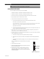
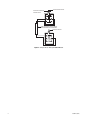
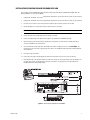
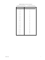
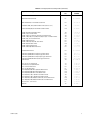
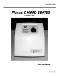
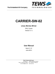
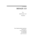
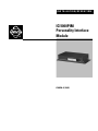
I N S TA L L AT I O N / O P E R AT I O N
®
ICI1000PIM
Personality Interface
Module
C1005M-G (10/02)
GENERAL
UNPACKING INSTRUCTIONS
Unpack and inspect all parts carefully.
The following items are supplied:
1
1
1
ICI1000PIM Personality Interface Module
RJ-14 cable for Inter-Check® and the DX2000 DVR
RJ-45 coupler for the DX2000 DVR
DESCRIPTION
The ICI1000PIM Personality Interface Module (PIM) is a data protocol translator that translates data from cash registers and
other devices for use with Pelco’s Inter-Check or DX2000 Digital Video Recorder (DVR).
Inter-Check is an automatic text insertion system that displays the data on a CCTV monitor. The DX2000 records video and
transaction data and lets the user view video and its associated data (if applicable) on a PC (personal computer).
2
C1005M-G (10/02)
INSTALLATION
NOTE: The information in this manual is for PIM software version 4.02 and above.
INSTALLATION FOR INTER-CHECK
Refer to the ICI1000S Inter-Check manual as you install the ICI1000PIM.
1. Configure DIP switch bank 1 on the PIM (refer to Configuring DIP Switch Bank 1 section).
2. Configure DIP switch bank 2 on the PIM (refer to Configuring DIP Switch Bank 2 section).
3. Locate the 16-pin connector on your register/interface. Plug the register/interface connector into the PIM.
4. Plug one data cable connector into the data connector in the PIM.
5. Connect the other end of the data cable in one of the following ways.
a.
If the Inter-Check and the PIM are within 6 feet (1.8 m) of each other, modify the cable as follows:
Refer to Figure 1 and slit the jacket to expose the wires.
Cut the red and green wires. To ensure the cut wires will not contact each other, either remove a section of the red
and green wires or, in case you want to reconnect the wires later, tape one end of the cut wires.
Plug the cable into the Inter-Check.
b.
If the Inter-Check and the PIM are more than 6 feet (1.8 m) apart, you must use the wiring kit. Refer to Figure 2. The
wiring kit is supplied with the ICI1000SE and ICI1000SI.
6. Mount the PIM inside or near the cash register or other device. Depending on the application, you may need to use
double-sided tape to secure the ICI1000PIM to the mount location.
7. Power-up the Inter-Check. To set all Inter-Check communication parameters to the specific values needed to communicate
with the ICI1000PIM module, do the following:
a.
Enter the main screen by pressing the ESC key and then the ENT key on the keypad.
b.
Once the main screen is present, press the #6 key selection (Diagnostics) and then the #8 key ([DL] PIM Default
Load).
c.
Press the #8 key until the loaded message appears on the screen, and then press the ESC key until the unit is
reinitialized.
(Refer to the C1000M-B manual if more detailed information on this procedure
is required.)
8.
Power-up the register or other device.
9. Connect the power plug into the PIM and plug the wall mount transformer into
power. This will power up the PIM.
10. Upon PIM power up, you should see a prompt that matches your register/
interface type displayed on the monitor. A PIM version number will also be
displayed. If this prompt appears on the monitor, the Inter-Check and the PIM
are communicating properly.
SLIT JACKET TO
EXPOSE WIRES
CUT RED AND
GREEN WIRES
Figure 1. Cable Modification
C1005M-G (10/02)
3
TO INTER-CHECK UNIT
STRAIGHT-THROUGH
PHONE CABLE
WHITE
BLUE
BLACK
YELLOW
RED
GREEN
USER-SUPPLIED CABLE, 18 AWG,
SHIELDED WIRE IS SUGGESTED
FROM ICI1000PIM
WHITE
BLUE
BLACK
YELLOW
RED
GREEN
Figure 2. Configuration for Wiring ICI1000PIM Module
4
C1005M-G (10/02)
INSTALLATION FOR DX2000 DVR AND DX2000DH DATA HUB
Refer to Figure 3 and the DX2000 Digital Video Recorder Installation/Operation Manual (C690M) and DX2000DH Data Hub
Manual (C698M) as you install the ICI1000PIM.
1.
Configure DIP switch bank 1 (refer to the Configuring DIP Switch Bank 1 section) for the device to which you are interfacing.
2.
Configure DIP switch bank 2 (refer to the Configuring DIP Switch Bank 2 section) for the device to which you are interfacing.
3.
Locate the 16-pin connector on your register/interface. Plug the register/interface connector into the PIM.
4.
Plug the provided RJ-14 (six-pin) phone cable into the data connector in the PIM.
NOTE: The provided RJ-14 phone cable is a straight-through cable. The PIM will not work with a flipped cable.
5.
Connect the other end of the data cable to the RJ-45 coupler provided.
6.
Connect a straight-pinned CAT 5 cable from the coupler to the DX2000 DVR or DX2000DH Data Hub.
7.
Mount the PIM near the register/interface. Depending on the application, you may need to use double-sided tape to
secure the ICI1000PIM to the mount location.
8.
On the Communication Type Setup tab of the DX2000’s Data Interface configuration screen, select Pelco PIM as the
communication type in the Device Type pull-down menu. Refer to the DX2000 Installation/Operation manual (C690M) for
more information.
9.
Power up the register/interface.
10. Connect the power plug to the PIM and plug the wall mount transformer into power. This powers up the PIM.
11. Upon PIM power-up, a message that matches your PIM switch settings for your register/interface type will appear in the
Live Data screen for the selected data device. A PIM version number is also displayed. This message indicates the
DX2000 and PIM are communicating properly.
Figure 3. Connecting the Components for DX2000
C1005M-G (10/02)
5
CONFIGURING DIP SWITCH BANK 1
The switches in this bank serve several purposes. Selections include polling or non-polling operation, PIM addressing, clock
signal manipulation, and ICI1000PIM graphics mode selection.
The following describes the DIP switch settings for bank 1 on the ICI1000PIM. (Refer to Figure 4 and Tables A and B).
NOTE: If data is garbled or non-existent and you have set the DIP switches correctly for your register, try setting switch 1 on
bank 1 to the opposite position of the standard setting that Pelco indicated.
Switch 1
This switch selects either the inverted or non-inverted clock signal. The switch setting varies depending on the
register/interface type selected for switch bank 2 from Table B.
Switch 2
This switch selects either polling or non-polling operation. Non-polling mode should be selected when using
the ICI1000SE or ICI1000SI Inter-Check. This mode is defined with a plus [+] switch setting.
The DX2000 already is set for non-polling, even in PIM graphics mode.
Switch 3
The function of this switch depends on the register/interface type used. In dot matrix cash register
applications, this switch selects either normal [–] or PIM graphics [+] mode. Other applications have selections
for monitor display of receipt or journal information. This switch is normally in the closed [–] position.
Switches 4-8
These switches set the addresses of multiple PIMs in a party-line system. The address selected normally will
coincide with the actual cash register number. The switch settings that correspond to PIM addresses are listed
in Table A.
CONFIGURING DIP SWITCH BANK 2
The switches in DIP switch bank 2 select the type of register/interface the ICI1000PIM interfaces. Table B indicates the switch
settings for specific register/interfaces. The first three switch settings have the same functions as switches 1-3 on DIP switch
bank 1. Refer to the Configuring DIP Switch Bank 1 section for detailed descriptions of these three switches.
Refer to Figure 4 and Table B to set the switches in bank 2.
ON
REGISTER/INTERFACE I NPUT
ON
1 2 3 4 5 6 7 8
1 2 3 4 5 6 7 8
BANK 1
BANK 2
DATA
POWER
Figure 4. ICI1000PIM Switch Locations
6
C1005M-G (10/02)
Table A. PIM Address Settings for Switch Bank 1
+ = OPEN (FLIP THE SWITCH DOWN)
C1005M-G (10/02)
– = CLOSED (FLIP THE SWITCH UP)
SWITCH # 45678
POLLING PIM ADDRESS (PIM #)
–––––
––––+
–––+–
–––++
––+––
––+–+
––++–
––+++
–+–––
–+––+
–+–+–
–+–++
–++––
–++–+
–+++–
–++++
+––––
+–––+
+––+–
+––++
+–+––
+–+–+
+–++–
+–+++
++–––
++––+
++–+–
++–++
+++––
+++–+
++++–
+++++
1
2
3
4
5
6
7
8
9
10
11
12
13
14
15
16
17
18
19
20
21
22
23
24
25
26
27
28
29
30
31
32
7
Table B. Cash Register/Interface Configurations
+ = OPEN (FLIP THE SWITCH DOWN)
– = CLOSED (FLIP THE SWITCH UP)
X = POLLING/NON-POLLING
– = POLLING
+ = NON-POLLING
Register/Interface Type
R = RECEIPT (Normally CLOSED = – )
– = JOURNAL
+ = SELECT
G = GRAPHICS (Normally CLOSED = – )
Bank 1 Switch
123
Bank 2 Switch
12345678
CASIO TK-2000 Dot Matrix Printer
CASIO TK4300 Dot Matrix Printer
CASIO TK1200/TK2600/TK4600/CE4115/CE4630 Dot Matrix Printer
CASIO TK2100/CE4530 Dot Matrix Printer
CASIO SA2000/2100 - Serial Printer
+XG
+XG
+XG
+XG
+X-
---+++----++++---++-++
---+++-+
---+++++
DATA CHECKER ALPHA 2/3 Printer, ICL MT20001
With Alpha 2/3 Printer
+XR
+--+--+-
DRESSER WAYNE Printer Serial
+XR
+---+++-
EPSON/Squirrel
+X-
+ - + - + - +-
ESPER 7100 Drum Printer
ESPER 7540/7810 Dot Matrix Printer
+X+XG
+--++--+--++--+
FUGITSU/ATRIUM Series with Bar 200 Printer
+XR
+--+----
GILBARCO TCR/G2 Parallel Printer
-XG
--------
HUGEN SWEDA - SWEDA 5436 Serial Printer
+X-
+----+--
+XR
+--+--++
+XR
+--+-+--
ICL-200 PTR, ICL-STORE MASTER 9518-200
ICL/DATA CHECKER MDL - 1600,1700,1800 Multidrop Connection
ICL/DTS 2000/2100/2200 EPSON 220-AF Dot Matrix Printer
ICL/DTS 2000/2100/2200 EPSON 220-F Dot Matrix Printer
+XR
+X+XG
+XG
+--+---+--+---+
--+------+----+
JCM GOLD 2200 Drum Printer
+X-
+--+-++-
MICROS 2700/3700
+X-
+-+-+--+
NCR 2127 With V3 MULTIFINCITON Printer - Serial
NCR 2121 Printer - Serial
NCR 2113 Printer - Serial
NCR ANSWER Printer SINGLE
NCR 1255/2140/2151/2152/2154/2157/2160/2552/2557
NCR 5300/SASI 1028/OLD STYLE Printer/MERIT REGISTER SYSTEMS
NCR ANSWER Printer DUAL - NCR 2126
NCR 7150-5001 Printer (7000 SERIES REG.)
NCR Register with RS-485 Printers 7150, 7156, 7193, and 2207
+X+X+
+X-
---++-+---++--+
---++---
-XR
-XR
+XR
+X-
---+-+----+-+-+
---+-+++-+---+-
NIXDORF
+X+
+--+++++
OMRON RS5550/RS5560 Dot Matrix Printer
OMRON 4510, 4541 Dot Matrix Printer
OMRON RS3410 Dot Matrix Printer
OMRON 4041, 4043 Dot Matrix Printer
-XG
-X-XG
+X-
--+---+--+---++
+----+-+
--+--+--
IBM Model 1/2 Printer, IBM4683/4684 with Model 1
or Model 2 Printer
IBM Model 3&4 Printer, IBM4683/4684 IBM4693/4694
with Model 3 Printer
(Continued on next page)
8
C1005M-G (10/02)
Table B. Cash Register/Interface Configurations (Continued)
Register/Interface Type
C1005M-G (10/02)
Bank 1 Switch
123
Bank 2 Switch
12345678
PANASONIC JS-6500 Dot Matrix Printer
-XG
+--++-++
RCALLEN RC204 Drum Printer
+X-
+--+-+++
RUBY VERIFONE/RS-232 Standard Serial Printer
+X+
+---+--+
SAMSUNG 4900, 4915, 4940 Dot Matrix Printer (Version 3 or 4)
-XG
--+--++-
SANYO ECR 580,690,720 EPSON 220F Dot Matrix Printer
+XG
+--++-+-
SHARP A430 DP630 Dot Matrix Printer
SHARP 2381/2391 Drum Printer
SHARP 3230/3231/3240/3241/4230/4231 Dot Matrix Printer
SHARP 3100/3100S/3110/3250/3252/3300/3310/3311 Dot Matrix Printer
SHARP 4230, 4231 Dot Matrix Printer
SHARP 2595 Drum Printer
SHARP 2385/2386/2395/2396 Drum Printer
SHARP A550 Dot Matrix Printer
SHARP 3220 Dot Matrix Printer
SHARP 2540/2590/2590S Drum Printer
-XG
+X+
-XG
-XG
- XG
+X+
+X+
+XG
-XG
+X+
--+--+-+
------+-----+-+
-----+++-+---------+-------++
----+-------+++
-------+
Standard Parallel Printer
+X+
+---++++
SWEDA 2810/OMRON RS14-30 (USA Type) Drum Printer
SWEDA 2810/OMRON RS14-40 (USA Type) Drum Printer
SWEDA 2810/OMRON RS14-40 (European Type) Drum Printer
SWEDA 2820/OMRON XXXX-XX (USA Type) Drum Printer
SWEDA 2860
+X+
+X+
+X+
+X+
-XG
+------+------+
+-----++-----++
+--+++-+
TEC 136/141/191/196 DISPLAY
TEC 206/216/227/230/290 DISPLAY
TEC 141 Printer Drum Printer
TEC 132/145 Drum Printer
TEC 2200/2300/2600 DPR-610/620 Dot Matrix Printer
TEC 2200/2300/2600 DPR-630 Dot Matrix Printer
TEC 2200/2300/2600 DPR-61A Dot Matrix Printer
TEC 1050/1060/1100/1190 DPR-710 Dot Matrix Printer
TEC 1050/1060/1100/1190 DPR-730 Dot Matrix Printer
TEC 1400/1600/1700/1900/FDS-30 DPR-370/374 Dot Matrix Printer
TEC 1400/1600/1700/1900/FSD-30 DPR-370S Dot Matrix Printer
-X+
-X+
+X+
+X+XG
+XG
+XG
-XG
-XG
+XG
+XG
----+--+
----+-+----+-++
+--+-+-+
----++-----++-+
----+++----++++
---+------+---+
---+--+-
TEC FT77 Printer - Serial Interface
+X-
---+--++
TOKHEIM
-XR
+--+++--
9
SPECIFICATIONS
ELECTRICAL
Power
Input Voltage:
120 VAC, 60 Hz to wall mounted transformer
(5 VDC, 300 mA from transformer to ICI1000PIM)
Connectors:
One 16-pin interface connector
One RJ-14 modular data connector
One transformer power connector
DIP Switches:
Two eight-position DIP switches
GENERAL
Construction:
Black plastic cover
Environment:
Indoor
Operating
Temperature:
32° to 120°F (0° to 49°C)
Weight:
Unit
1.80 lb (0.82 kg)
Dimensions:
0.75" H x 4.94" W x 2.75" D (1.91 x 12.55 x 6.99 cm)
Shipping
3.0 lb (1.36 kg)
(Design and specifications are subject to change without notice.)
10
C1005M-G (10/02)
WARRANTY AND RETURN INFORMATION
WARRANTY
Pelco will repair or replace, without charge, any merchandise proved defective in material or
workmanship for a period of one year after the date of shipment. Exceptions to this warranty are
as noted below:
• Five years on Pelco manufactured cameras (CC3500/CC3600/CC3700 and MC3500/MC3600
Series); two years on all other cameras.
• Three years on Genex® Series (multiplexers, server, and keyboard).
• Two years all standard motorized or fixed focal length lenses.
• Two years on Legacy®, Camclosure® Camera Systems, CM6700/CM6800/CM8500/CM9500/
CM9740/CM9760 Matrix, DF5 and DF8 Series Fixed Dome products.
• Two years on Spectra®, Esprit®, and PS20 Scanners, including when used in continuous
motion applications.
• Two years on WW5700 series window wiper (excluding wiper blades).
• Eighteen months on DX Series digital video recorders.
• One year (except video heads) on video cassette recorders (VCRs). Video heads will be
covered for a period of six months.
• Six months on all pan and tilts, scanners or preset lenses used in continuous motion applications (that is, preset scan, tour and auto scan modes).
If a warranty repair is required, the Dealer must contact Pelco at (800) 289-9100 or (559) 292-1981 to
obtain a Repair Authorization number (RA), and provide the following information:
1. Model and serial number
2. Date of shipment, P.O. number, Sales Order number, or Pelco invoice number
3. Details of the defect or problem
If there is a dispute regarding the warranty of a product which does not fall under the warranty conditions
stated above, please include a written explanation with the product when returned.
Method of return shipment shall be the same or equal to the method by which the item was received by
Pelco.
RETURNS
In order to expedite parts returned to the factory for repair or credit, please call the factory at (800) 2899100 or (559) 292-1981 to obtain an authorization number (CA number if returned for credit, and RA
number if returned for repair).
All merchandise returned for credit may be subject to a 20% restocking and refurbishing charge.
Pelco will warrant all replacement parts and repairs for 90 days from the date of Pelco
shipment. All goods requiring warranty repair shall be sent freight prepaid to Pelco, Clovis,
California. Repairs made necessary by reason of misuse, alteration, normal wear, or accident
are not covered under this warranty.
Pelco assumes no risk and shall be subject to no liability for damages or loss resulting from the
specific use or application made of the Products. Pelco’s liability for any claim, whether based on
breach of contract, negligence, infringement of any rights of any party or product liability, relating
to the Products shall not exceed the price paid by the Dealer to Pelco for such Products. In no
event will Pelco be liable for any special, incidental or consequential damages (including loss of
use, loss of profit and claims of third parties) however caused, whether by the negligence of
Pelco or otherwise.
The above warranty provides the Dealer with specific legal rights. The Dealer may also have
additional rights, which are subject to variation from state to state.
Goods returned for repair or credit should be clearly identified with the assigned CA or RA number and
freight should be prepaid. Ship to the appropriate address below.
If you are located within the continental U.S., Alaska, Hawaii or Puerto Rico:
Service Department
Pelco
3500 Pelco Way
Clovis, CA 93612-5699
If you are located outside the continental U.S., Alaska, Hawaii or Puerto Rico:
Intermediate Consignee
Ultimate Consignee
American Overseas Air Freight
Pelco
320 Beach Road
3500 Pelco Way
Burlingame, CA 94010
Clovis, CA 93612-5699
USA
USA
REVISION HISTORY
Manual #
C1005M
C1005M-A
C1005M-B
Date
C1005M-C
C1005M-D
C1005M-E
8/93
9/93
9/94
9/95
1/96
8/98
C1005M-F
C1005M-G
8/02
10/02
Comments
Original version.
Minor revisions to manual.
Addendum changes to manual.
Changed manual to new format and minor revisions.
Minor revisons to manual.
Minor revisons to manual.
Changed manual to new format. Revised the installation and operation instructions and added configuration settings for Epson/Squirrel, Micros 2700, NCR
register with RS-485 printers, Ruby Verifone, and standard parallel printer.
Changed manual to new format. Revised the manual to add DX2000 DVR material. Replaced Figure 3 with a different drawing.
Expanded instructions for executing a PIM DEFAULT LOAD (DL). Included statement that the DX2000 is set for non-polling.
® Pelco, the Pelco logo, Spectra, Genex, Legacy, Esprit and Camclosure are registered trademarks of Pelco.
C1005M-G (10/02)
© Copyright 2002, Pelco. All rights reserved.
11
®
World Headquarters
3500 Pelco Way
Clovis, California 93612 USA
USA & Canada
Tel: 800/289-9100
Fax: 800/289-9150
International
Tel: 1-559/292-1981
Fax: 1-559/348-1120
www.pelco.com
ISO9001
Orangeburg, New York Las Vegas, Nevada Eindhoven, The Netherlands Wokingham, United Kingdom Montreal, Canada