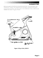
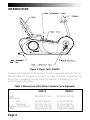
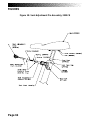
1
Stratus Systems Owner’s Manual ® Printed in the United States. ©1997 StairMaster Sports/Medical Products, Inc. All rights reserved. Corporate Headquarters 12421 Willows Road N.E., Suite 100 Kirkland, WA 98034 (800) 635-2936 (425) 823-1825 Fax (425) 823-9490 www.stairmaster.com P/N 21442-F ©1997 StairMaster Sports/Medical Products, Inc. and StairMaster are either a registered trademark or trademark of StairMaster Sports/Medical Products, Inc. in the United States and/or other countries. Page iii WARRANTY This is to certify that the StairMaster® Stratus systems cycle ergometer is warranted for a period of three years by StairMaster Sports/Medical Products Inc. to be free of all defects in materials and workmanship. This warranty does not apply to any defect caused by negligence, misuse, accident, alteration, improper maintenance, or an “act of God.” This warranty is nontransferable from the original owner. If, within three years from the date of purchase, any part of the StairMaster Stratus systems cycle ergometer should fail to operate properly (except any accessories or the battery), contact our Customer Service Department to report the problem. International customers should contact their local distributor. When calling, please be prepared to provide our customer service representative with the following information: • • • • • Your name, shipping address, and telephone number; The model number of the inoperable unit; The serial number of the inoperable unit (located on the frame); The date(s) of purchase for the inoperable unit(s); Your billing address. This information will ensure that you are the only one ordering parts under your warranty protection. If warranty replacement parts are shipped to you, you may be required to return the inoperable part. To facilitate this process, the following policy has been established: • Please call our Customer Service Department to receive a return goods authorization prior to shipment. • StairMaster Sports/Medical Products, Inc. will incur all freight (i.e., shipping and handling) charges for warranty parts ordered for a product that is less than 45 days old. The parts will be shipped to you via an overnight courier. • The customer is responsible for freight charges on warranty parts for products that are more than 45 days old. Customers will not be responsible for the return shipment of the inoperable parts (see below). • Some inoperable warranty parts must be promptly returned to our Customer Service Department. We will pay the shipping cost for the inoperable warranty parts. Detailed instructions are included with each warranty replacement part shipment. StairMaster Sports/Medical Products, Inc. neither makes, assumes, nor authorizes any representative or other person to make or assume for us, any other warranties whatsoever, whether expressed or implied, in connection with the sale, service, or shipment of our products. We reserve the right to make changes and improvements in our products without incurring any obligation to similarly alter products previously purchased. In order to maintain your product warranty and to ensure the safe and efficient operation of your StairMaster Stratus systems cycle ergometer, only authorized replacement parts can be used. This warranty is void if any parts other than those provided by StairMaster Sports/Medical Products, Inc. are used. * Note: Aerosol products cannot be transported via air. Page iv PREFACE The StairMaster® Stratus systems cycle ergometer is a safe and effective way to develop aerobic fitness while conditioning the major muscles of the lower body. In order to get the best results, and to keep your machine in peak operating condition, you should carefully read and follow the guidelines presented in this manual. WHAT IS IN THIS MANUAL? This manual includes sections on safety, installation, operating instructions, preventive maintenance, and detailed information on troubleshooting and repair procedures. An appendix at the end of the manual provides important phone numbers and drawings. WHAT IS THE STAIRMASTER STRATUS CYCLE ERGOMETER? The Stratus systems cycle ergometers have 14 levels of intensity for the MANUAL program and 20 levels of intensity for the other programs. The Stratus uses a variable resistance system to maintain constant power within any given intensity level. The resistance decreases as you pedal faster and increases as you pedal slower. The variable resistance system ensures you will do the same amount of work regardless of how fast or slow you pedal. WHAT IS THE BATTERY CHARGER USED FOR? Plug in the battery charger only to recharge a weak battery. Exercising on the Stratus cycle while the battery charger is connected will not damage the machine, but will affect the power output (watts) statistics. Page v CONTENTS SAFETY GUIDELINES ....................................................................................... 1 INTRODUCTION ................................................................................................ 3 INSTALLATION INSTRUCTIONS..................................................................... 5 BASIC OPERATING INSTRUCTIONS ............................................................. 6 Adjustments .......................................................................................... 6 The ATTRACT Mode .............................................................................. 7 HEART RATE MONITOR ................................................................................... 9 CONSOLE ........................................................................................................... 10 Text Bar ................................................................................................. 10 Display .................................................................................................. 10 Function Keypad .................................................................................... 11 Exercise Program Keypad ..................................................................... 13 Road Race ............................................................................................. 22 Custom Exercise Programs.................................................................... 23 Custom Scrolling Message ................................................................... 24 Editing the Scrolling Message .............................................................. 25 Set Maximum Workout Length ............................................................. 26 Changing to the Clinical Mode ............................................................. 26 Changing the Console Units and Prompt Language ............................. 26 Console Codes ...................................................................................... 27 MAINTENANCE INSTRUCTIONS ................................................................... 28 Helpful Hints ......................................................................................... 28 Tool List ................................................................................................. 28 Maintenance Records ........................................................................... 28 Initial Service ........................................................................................ 29 Preventive Maintenance ....................................................................... 29 TROUBLESHOOTING GUIDELINES ................................................................ 33 Systematic Electrical Troubleshooting .................................................. 33 Console Diagnostic Tests ...................................................................... 36 Systematic Mechanical Troubleshooting .............................................. 38 Page vi CONTENTS PARTS REMOVAL AND REPLACEMENT ....................................................... 40 Console ................................................................................................. 41 Covers ................................................................................................... 40 Crank and Bottom Bracket Assembly .................................................... 47 Drive Chain ............................................................................................ 45 Intermediate Shaft Assembly ............................................................... 46 Handlebar Assembly ............................................................................. 42 Pedals .................................................................................................... 47 Seat ....................................................................................................... 43 Seat Location Post (3300 CE only) ........................................................ 44 Seat Track (3900 RC only) ..................................................................... 45 GROUNDING INSTRUCTIONS ........................................................................ 50 NOTICE OF FCC COMPLIANCE ....................................................................... 51 APPENDICES Important Phone Numbers .................................................................... 52 Battery Recycling Centers ..................................................................... 53 Figures 11 - 24 ...................................................................................... 55 Wiring Diagram ..................................................................................... 69 LIST OF TABLES Table 1: Specifications ........................................................................................ 4 Table 2: Fitness Rating Norms ............................................................................. 15 Table 3: Character Codes ..................................................................................... 25 Table 4: Console Codes ....................................................................................... 27 Table 5: Preventive Maintenance Schedule ........................................................ 32 LIST OF ILLUSTRATIONS Figure 1: Major Parts, 3300 CE ............................................................................ 3 Figure 2: Major Parts, 3900 RC ............................................................................ 4 Figure 3: End Caps ............................................................................................... 5 Figure 4: Stratus Systems Console ...................................................................... 10 Figure 5: Fat Burner ............................................................................................. 16 Figure 6: Fat Burner Plus ...................................................................................... 17 Page vii CONTENTS Figure 7: Rolling Hills ........................................................................................... 18 Figure 8: Aerobic Training .................................................................................... 19 Figure 9: Cross Country ........................................................................................ 20 Figure 10: Speed Training .................................................................................... 21 Figure 11: Cover Fasteners .................................................................................. 55 Figure 12: Cover Fastener Location, 3300 CE ...................................................... 56 Figure 13: Cover Fastener Location, 3900 RC ...................................................... 57 Figure 14: Right Side View, 3300 CE ................................................................... 58 Figure 15: Left Side View, 3300 CE ..................................................................... 59 Figure 16: Right Side View, 3900 RC ................................................................... 60 Figure 17: Left Side View, 3900 RC ..................................................................... 61 Figure 18: Seat Adjustment Pin Assembly, 3300 CE ........................................... 62 Figure 19: Seat Assembly, 3900 RC ..................................................................... 63 Figure 20: Drive Chain Tension ............................................................................ 64 Figure 21: Intermediate Shaft Assembly ............................................................. 65 Figure 22: J Bolt Assembly .................................................................................. 66 Figure 23: Crank Assembly .................................................................................. 67 Figure 24: Alternator/Flywheel Assembly ........................................................... 68 Wiring Diagram 1: Wiring Schematic ................................................................. 69 Page viii SAFETY GUIDELINES IMPORTANT SAFETY INSTRUCTIONS When using electrical equipment, basic precautions should always be followed, including: Read all instructions before using the machine. DANGER To reduce the risk of electric shock, always unplug the battery charger from the AC wall outlet before cleaning, maintaining, or repairing. WARNING To reduce the risk of burns, electric shock, or injury to persons: 1. The battery charger should always be unplugged from the AC wall outlet before removing or installing parts. Never make adjustments or repairs while an exercise program is in progress. 2. Close supervision is necessary whenever the machine is used by or near children, invalids, or disabled persons. 3. Keep your hands away from all moving parts and keep your feet on the pedals while exercising. Do not operate with the side covers removed. 4. Use this machine only for its intended use as described in this Manual. Do not use attachments or accessories other than those provided by StairMaster® Sports/Medical Products, Inc.. 5. Do not use the battery charger if it has a damaged cord or plug, if it is not working properly, if it has been dropped or damaged, or dropped into water. Contact our Customer Service Department to arrange for the return of damaged parts. Refer to the Appendix for the appropriate phone number. Page 1 SAFETY GUIDELINES 6. Connect the battery charger to a properly grounded AC wall outlet; refer to the "Grounding Instructions" section. Keep all cords away from heated surfaces. 7. Never drop or insert any object into any opening on the machine (except when lubricating the machine). 8. Do not use the machine outdoors. 9. Do not operate where aerosol (spray) products are being used or where oxygen is being administered. 10. Always wear insulated gloves when handling batteries. 11. Do not crush, incinerate, or dismantle the battery. The electrolyte contains sulfuric acid which can cause serious damage to eyes and skin. Should this occur, flush profusely with water and seek medical attention. 12. To disconnect the battery charger, remove the plug from the AC wall outlet. The safety level given by the design of this equipment can only be maintained when the equipment is regularly examined for damage and wear. Inoperable components shall be replaced immediately or the equipment shall be put out of use until it is repaired. Failure to follow all guidelines may compromise the effectiveness of the exercise experience, expose yourself (and possibly others) to injury, and reduce the longevity of the machine. SAVE THESE INSTRUCTIONS Page 2 INTRODUCTION Before leaving the StairMaster manufacturing facility in Tulsa, Oklahoma, your StairMaster® Stratus cycle ergometer was thoroughly inspected and tested to ensure proper operation. The major parts of the StairMaster Stratus 3300 CE and 3900 RC are shown in Figures 1 and 2. Figure 1: Major Parts, 3300 CE Page 3 INTRODUCTION Figure 2: Major Parts, 3900 RC Throughout this manual, all references to the left or right side and to the front or back are made as if you were on the machine, ready to exercise. For example, the drive chain is located on the right side of the machine. The dimensions of the machine are listed in Table 1. Table 1. Dimensions of the Stratus Systems Cycle Ergometer 3300 CE Length Width at the: base handlebars Height at the handlebars Weight Page 4 3900 RC 46 inches (117 cm) 62 inches (157 cm) 19 inches (48 cm) 22 inches ( 56 cm) 57 inches (145 cm) 125 pounds (57 kg) 19 inches (48 cm) 22 inches (48 cm) 42 inches (107 cm) 150 pounds (68 kg) INSTALLATION INSTRUCTIONS Assemble your machine before use. Machines shipped outside the United States need to be uncrated before they can be assembled; refer to the “Uncrating Instructions” included with your machine for the details. 1. Remove all shipping material and the battery charger from the console. 2. Make sure the machine is level before you use it for the first time. The four rubber end caps (see Figure 3) are designed to compensate for slightly uneven floors. Each face of the caps is a different thickness. Twist the caps to stabilize the machine. Figure 3: End Caps 3. Pedal the cycle to turn on the console. The console should produce an audible sound and display a simulated EKG signal in the display area. If it does not, contact our Customer Service Department. Refer to the Appendix for the appropriate phone number. Page 5 BASIC OPERATING INSTRUCTIONS ADJUSTMENTS You should check two adjustments before using your StairMaster® Stratus systems cycle ergometer: the seat height and the pedal footstrap length. Seat Height Adjustment on the Stratus 3300 CE Cycle Ergometer Sit on the seat. Put both feet onto the pedals and into the footstraps. Pedal slowly and then stop when one leg is extended and your foot is as close to the floor as possible. The knee of the extended leg should be slightly bent when the sole of your foot is parallel to the floor. If you need to adjust the seat height, get off the bike and stand to one side. The seat adjustment knob is located on the frame tube just below the front part of the seat. Hold onto the seat with one hand and pull out on the seat adjustment knob with your other hand. You may need to lift up on the seat to disengage the seat pin. Lower or raise the seat as necessary. ! WARNING TO ELIMINATE THE RISK OF INJURY, DO NOT ADJUST THE SEAT HEIGHT WHILE ON THE STRATUS 3300 CE CYCLE ERGOMETER. MAKE SURE THAT THE SEAT ADJUSTMENT PIN COMPLETELY ENGAGES THE HOLE IN THE SEAT POST BEFORE REMOUNTING THE BIKE. Seat Adjustment on the Stratus 3900 RC Cycle Ergometer Sit on the seat. Put both feet onto the pedals and into the footstraps. Pedal slowly and then stop when one leg is extended. The knee of the extended leg should be slightly bent. The seat adjustment lever is in front of the seat base. Remain seated and keep your feet on the pedals. Pull up on the lever and slide forward or backward as necessary. Release the lever and make sure the seat is locked in place by trying to move the seat forward and backward. Page 6 BASIC OPERATING INSTRUCTIONS Footstrap Adjustment To ensure your feet are properly secured to the pedals, you need to check the position of the footstraps. Position your foot so that the ball of your foot is over the pedal spindle. The pedal footstraps should be tight enough to secure your feet to the pedals but not so tight so as to cut off the circulation. If you need to adjust the footstrap length, get off the bike and stand to one side. There are two adjusting holes on the inside footstrap mount and four holes on the outside footstrap mount. Most shoes can be accommodated by adjusting the outside mounting holes. To make the necessary adjustments, grasp the pedal with one hand and the outside end of the footstrap with your other hand. Carefully pull the outside end of the footstrap off the tab on the pedal. Insert the proper hole of the footstrap onto the pedal tab. If you need to make additional adjustments, repeat the process with the inside mounting holes of the footstrap. THE ATTRACT MODE All workouts on the StairMaster® Stratus cycle ergometer start from the ATTRACT mode. The console displays an EKG signal or scrolls a message in the text bar when it is in the ATTRACT mode. You must pedal to get the console into the ATTRACT mode. You can customize the ATTRACT mode by programming your own scrolling message. Refer to the “Customizing the Text Bar Scrolling Message” section for instructions. BASIC INSTRUCTIONS FOR FIRST-TIME USERS 1. Warm up with light calisthenics and easy stretching exercises for at least five minutes before beginning your exercise program. ! WARNING IF AT ANY TIME DURING YOUR WORKOUT YOU FEEL CHEST PAIN, EXPERIENCE SEVERE MUSCULAR DISCOMFORT, FEEL FAINT, OR ARE SHORT OF BREATH, STOP EXERCISING IMMEDIATELY. IF THE CONDITION PERSISTS, YOU SHOULD CONSULT YOUR MEDICAL DOCTOR IMMEDIATELY. Page 7 BASIC OPERATING INSTRUCTIONS 2. Position yourself comfortably on the bike and begin pedaling. 3. Select the MANUAL exercise program so you can control the pace of your first workout and get used to the exercise motion. Console Set-Up 1. Press [MANUAL] and then press [ENTER]. 2. The console will prompt you to enter your body weight. Enter your weight in pounds (or kilograms if the console is set up for metric units). Correct entry errors by pressing [CLEAR] before you press [ENTER]. 3. The console will prompt you to enter the workout time in one minute increments between five and 60 minutes. Press [1], [0], [ENTER] to exercise for ten minutes. Begin Exercising 1. Pedal at a comfortable pace. Although the resistance decreases as you pedal faster, the intensity (watts) stays the same. 2. Press [+ ARROW] and [- ARROW] to adjust your intensity level. 3. Select an intensity level that allows you to stay at a comfortable pace. Harder is not always better. Exercise at a level that is consistent with your fitness level. 4. The intensity (watts) remains constant provided you pedal at least 50 RPM. A message will prompt you to "Pedal Faster" if you pedal slower than 50 RPM. 5. Cool down after you get off the machine by walking or stretching for at least five minutes. Page 8 HEART RATE MONITOR The StairMaster® Stratus Systems cycle ergometer features Polar® heart rate monitoring. The system consists of the receiver, located near the front of the cycle, and a transmitter belt, available separately from your StairMaster representative, worn across your chest. The transmitter belt senses the heart beat and sends a signal to the receiver. Your heart rate, in beats per minute, is shown on the console text bar. Before you put the transmitter belt on, wet the two contact patches (the grooved rectangles on the reverse side of the belt). Secure the transmitter belt as high under the pectoral muscles (breasts) as is comfortable. The transmitter belt should fit snugly and comfortably and allow normal breathing. When the console detects a heart rate signal, heart rate is shown in the display automatically. The word "PULSE", your heart rate in beats per minute, and a pulsing heart icon are displayed in the text bar. If you display a statistic other than heart rate during your workout, you can return to heart rate by pressing [PULSE] once or any other statistic key twice. Heart rate is part of the workout stats scrolling display. Average heart rate is shown at the end of your workout. If you wear a transmitter strap during the Fit Test, the average heart rate at the end of each stage is automatically used when estimating maximum aerobic capacity. Page 9 STRATUS SYSTEMS CONSOLE The StairMaster® Stratus systems console is divided into four sections: the text bar, the display, the function keypad and the exercise program keypad (see Figure 4). Figure 4: Stratus Systems Console TEXT BAR Information regarding workout statistics and data entry is displayed or scrolled across the text bar. A countdown timer is located directly above the words "Interval Time". The timer shows the number of seconds remaining in the current interval. DISPLAY A profile of all exercise programs (except MANUAL and FIT TEST) appears in the display when you press its key. The taller the column, the higher the intensity (watts) for that interval. The flashing column shows your current interval. The flashing column moves from left to right across the display as you complete each interval. Page 10 STRATUS SYSTEMS CONSOLE Function keypad The function keypad is located on the right side of the console. Nine of the keys on the keypad have two pieces of information on them—a number and a workout statistic. Before the exercise program begins, the numbers are used to enter data in response to the console prompts. During or immediately after the exercise program, the function keypad keys are used to recall workout statistics which are then displayed on the text bar. Time. Displays the elapsed time of your workout, in minutes and seconds. Speed. Displays the equivalent speed, in miles per hour (or kilometers per hour if your console is set to metric units), you would be traveling on a bicycle outdoors while riding at the same relative intensity. Distance. Provides a cumulative total of the equivalent distance, in miles (or kilometers if your console is set to metric units), you would have traveled while riding a bicycle outdoors at the same relative intensity. Watts. Displays the intensity in watts (746 watts = 1 horsepower). For all programs, except the constant resistance ROAD RACE, the watts remain constant in any given level as long as you pedal at least 50 RPM. During a workout, this key displays the power output at that moment. Average power is shown during the workout summary. Intensity Level. Shows the current level between 1 (the easiest) and 20 (the hardest). Shows the number of lights in the MANUAL program between 1 and 14. METs. Gives you the relative energy cost of exercise. MET stands for multiples of the resting metabolic rate. While you are sitting quietly, your body consumes oxygen at the rate of about 3.5 milliliters per kilogram of body mass per minute. When you exercise, your body needs more oxygen in order to function. For example, exercising at 10 METs requires ten times the resting rate of oxygen consumption, or Page 11 STRATUS SYSTEMS CONSOLE about 35 milliliters per kilogram per minute. During a workout, this key shows the current MET level. During the workout summary, the average MET level is displayed. Calories. Provides a running total of the number of Calories burned during a workout. Enter. Confirms workout selections and stores the information used by the console to calculate workout statistics. Clear. Erases information from the console memory if pressed before [ENTER]. [+] and [-] ARROWS. Increases or decreases the intensity level. Workout Stats. If pressed during your workout, all workout statistics continuously scroll across the text bar. Press any key to stop scrolling at that statistic. If [WORKOUT STATS] is pressed immediately after your workout, the workout summary statistics will scroll once across the text bar. Press any key to stop scrolling at that statistic. If [WORKOUT STATS] is pressed while the console is in the ATTRACT mode, the final totals from the last workout will scroll across the text bar. This summary is stored in the console memory until the next workout is started. Yes and No. Respond to console prompts. Start/Stop. If pressed while the console is in the ATTRACT mode, the console will display the "Select A Program" prompt. If it is pressed at any other time, the console will pause for 10 seconds. Page 12 STRATUS SYSTEMS CONSOLE EXERCISE PROGRAM KEYPAD The purple exercise keypad is located below the display and to the left of the function keypad. While the console is in the ATTRACT mode, press one of the exercise program keys to preview the desired workout. The sequence of prompts for the preset exercise programs is slightly different than the sequence described earlier for the MANUAL program. After you press one of the exercise program keys, the exercise program profile is scrolled across the display. After the profile is scrolled, the prompts are: • • • • “PRESS ENTER KEY TO SELECT” “ENTER BODY WEIGHT” -- type in your body weight in pounds (or kilograms if your console is set to metric units). “ENTER LEVEL 1 - 20” -- select your intensity level with level 1 being the easiest and level 20 the hardest. “ENTER TIME 5 - 60” -- select the workout duration in one minute increments from five to 60. The Quick Start Option You can begin a manually-paced workout without pressing any keys just by pedaling for 15 seconds. This program will last for 15 minutes. You can quickly start a preset workout by first pressing one of the purple exercise program keys and then pressing [ENTER] twice. You do not have to enter any other information. The length of the workout is set automatically and varies with the program. Quick starting MANUAL gives you a 15 minute workout. The preset workouts last five minutes for every thirty intervals. So, a 60 interval program will last 10 minutes. The workout stats available are time, speed, distance, watts, level, calories, RPM, and pulse (if wearing a transmitter). The Fit Test does not have a quick start option. Page 13 STRATUS SYSTEMS CONSOLE Fit Test The Fit Test is a program developed by the YMCA to estimate your maximum aerobic capacity based on your heart rate response to submaximal exercise. Start the Fit Test by pressing [FIT TEST], [ENTER]. You will be prompted to enter your weight, age, and gender after a short message is scrolled across the text bar. The Fit Test is a series of three minute stages of increasing intensity. Maintain a steady pedal rate of 50 - 70 RPM throughout the entire test. The first stage is a warm-up at 50 watts. At the end of the three minute (180 seconds) warm-up, you will need to enter your heart rate. If you are wearing a heart rate transmitter, your heart rate is entered automatically. NOTE: Keep pedaling until the end of the Fit Test. The results will be invalid if you do not maintain a steady pedal rate for the entire test. The console will prompt you to find your pulse; use the artery below your thumb in your wrist or the artery in the side of your neck. Start counting the beats when the console prompts you--the first beat you feel is zero and then one and so on. Enter the number of beats you counted in ten seconds. The intensity of the remaining stages is based on your heart rate response to the warm-up. The intensity of each successive stage will increase until you have entered two consecutive heart rates between 19 and 25 counts (115 - 150 beats per minute). The test typically lasts from nine to 15 minutes. At the end of the Fit Test, your results scroll across the text bar. Prior to a three minute cool-down, your estimated maximum aerobic capacity is shown in METs. Next, your results are compared to normative values for others of your age and gender (see Table 2). Your results are stored in the console until the next person starts an exercise program. Press [WORKOUT STATS] to review your results. Page 14 STRATUS SYSTEMS CONSOLE ○ ○ ○ ○ ○ ○ ○ ○ ○ ○ ○ ○ ○ ○ ○ ○ ○ ○ ○ ○ ○ ○ ○ ○ ○ ○ ○ ○ ○ ○ ○ ○ ○ ○ ○ ○ ○ ○ ○ ○ ○ ○ ○ ○ ○ ○ ○ ○ ○ ○ ○ ○ ○ ○ ○ ○ ○ ○ ○ ○ ○ ○ ○ ○ ○ ○ ○ ○ ○ ○ ○ ○ ○ ○ ○ 20.0+ 18.6+ 17.4+ 16.0+ 14.3+ ○ ○ ○ ○ ○ ○ ○ ○ ○ ○ ○ ○ ○ ○ ○ ○ ○ ○ ○ ○ ○ 14.0-16.8 13.7-16.6 13.1-16.0 12.0-14.0 10.6-12.6 ○ 10.0-13.7 9.7-13.4 9.1-12.8 8.0-11.7 6.6-10.3 ○ ○ ○ ○ ○ ○ ○ ○ ○ ○ ○ ○ ○ ○ ○ ○ ○ ○ ○ ○ ○ ○ ○ ○ ○ ○ ○ ○ ○ ○ ○ ○ ○ ○ ○ ○ ○ ○ ○ ○ ○ ○ ○ ○ ○ ○ ○ ○ 17.1+ 16.8+ 16.3+ 14.3+ 12.8+v ○ ○ ○ ○ ○ ○ ○ ○ ○ ○ ○ ○ ○ ○ ○ ○ ○ ○ ○ ○ ○ ○ ○ ○ ○ ○ 8.3-9.7 8.0-9.4 7.4-8.8 6.3-7.7 5.1-6.3 ○ ○ ○ ○ Superior ○ ○ ○ ○ ○ ○ ○ ○ ○ ○ ○ ○ ○ ○ ○ ○ ○ ○ ○ ○ ○ ○ ○ ○ ○ ○ ○ ○ ○ ○ ○ ○ ○ ○ ○ ○ ○ ○ ○ ○ ○ ○ ○ ○ ○ ○ ○ ○ ○ ○ ○ ○ ○ ○ ○ ○ ○ ○ ○ ○ ○ ○ ○ ○ ○ ○ ○ ○ ○ ○ ○ ○ ○ ○ ○ ○ ○ ○ ○ ○ ○ ○ ○ ○ 16.3-19.7 14.8-18.3 13.7-17.1 12.6-15.7 11.4-14.0 ○ ○ ○ ○ ○ ○ ○ ○ ○ ○ ○ ○ ○ ○ ○ ○ ○ ○ ○ ○ ○ ○ ○ ○ <8.0 <7.7 <7.1 <6.0 <4.8 ○ ○ ○ ○ ○ ○ ○ ○ ○ ○ ○ Above Average ○ ○ ○ ○ ○ ○ ○ ○ ○ ○ ○ 12.6-16.0 11.4-14.6 10.3-13.4 9.1-12.3 7.7-11.1 ○ ○ ○ ○ ○ ○ ○ ○ ○ ○ ○ ○ ○ ○ ○ ○ ○ ○ ○ ○ ○ ○ ○ ○ ○ ○ ○ ○ ○ ○ ○ ○ ○ ○ ○ ○ ○ ○ ○ ○ ○ ○ ○ ○ ○ ○ ○ ○ ○ ○ ○ 11.1-12.3 10.0-11.1 8.8-10.0 7.4-8.8 6.3-7.4 ○ ○ ○ ○ ○ ○ ○ Average ○ ○ ○ ○ ○ ○ ○ ○ ○ ○ ○ ○ ○ ○ <10.8 <9.7 <8.6 <7.1 <6.0 ○ ○ ○ ○ ○ ○ ○ ○ ○ ○ ○ ○ ○ ○ ○ ○ Fair ○ ○ ○ ○ ○ ○ ○ ○ ○ ○ Men 20-29 30-39 40-49 50-59 60-69 Women 20-29 30-39 40-49 50-59 60-69 Low ○ Rating Gender/Age ○ ○ ○ Table 2. Fitness Rating Norms for Stratus Systems Cycle Ergometer Aerobic Fitness Test (METs) Preset Exercise Programs There are seven preset exercise programs. The exercise intensity (watts) during the programs varies automatically over 14 increments within each of the 20 different levels. Varying the intensity level of an exercise program does not change the profile shown on the display. Change the intensity level of your workout by pressing [+ ARROW] or [- ARROW]. For each level, the average energy cost of all programs is about the same. Page 15 STRATUS SYSTEMS CONSOLE The Fat Burner program (Figure 5) is a 60 interval workout designed for people just starting a weight control program. The Fat Burner Plus program (Figure 6) is similar but has 90 intervals. It is meant for the longer workouts you will need as your fitness level increases. Figure 5a: Fat Burner, Screen 1 Figure 5b: Fat Burner, Screen 2 Page 16 STRATUS SYSTEMS CONSOLE Figure 6a: Fat Burner Plus, Screen 1 Figure 6b: Fat Burner Plus, Screen 2 Figure 6c: Fat Burner Plus, Screen 3 Page 17 STRATUS SYSTEMS CONSOLE Rolling Hills (Figure 7) is a 30 interval workout with gradual speed changes. It is geared for those who are just starting to exercise or for those who need an easy day of recovery exercise. Figure 7: Rolling Hills Page 18 STRATUS SYSTEMS CONSOLE Aerobic Training (Figure 8) is a 60 interval workout with slightly more varied speed changes. It is ideal for those long, slow workouts to increase your aerobic capacity. Figure 8a: Aerobic Training, Screen 1 Figure 8b: Aerobic Training, Screen 2 Page 19 STRATUS SYSTEMS CONSOLE Cross Country and Speed Training (Figures 9 and 10) are 90 interval workouts with lots of speed changes to get your legs moving. Think of the terrain you would find on a hike cross country. Figure 9a: Cross Country, Screen 1 Figure 9b: Cross Country, Screen 2 Figure 9c: Cross Country, Screen 3 Page 20 STRATUS SYSTEMS CONSOLE Figure 10a: Speed Training, Screen 1 Figure 10b: Speed Training, Screen 2 Figure 10c: Speed Training, Screen 3 Page 21 STRATUS SYSTEMS CONSOLE ROAD RACE 1. The Road Race is a unique program that places the user in a race against a computer pacer. 2. The Road Race uses a resistance system that increases the resistance as you pedal faster, just like a real bicycle. The faster you pedal, the heavier the resistance, and the faster you will travel. 3. Start the Road Race program by pressing [ROAD RACE] and then [ENTER]. Input your weight, and the total race distance in miles (or Kilometers, if your console is set to metric units). 4. Enter the level. You can change the pacer's speed at anytime during the race. Use the [+ ARROW] or [- ARROW] to change the speed. 5. The console will be count down to the start of the race. Start pedaling when the word “GO !” appears in the text bar. 6. Three lights will appear at the bottom of the display. The two outside dots are you, and the inside dot is the pacer. Your progress, and the pacer’s, is shown by lit LEDs. 7. Each lap of the display area is 0.25 miles (0.25 kilometers) 8. When the cyclist or the pacer enters the last lap, the entire track lights up. As the finish line is approached, each LED corresponding to the current position is turned off. 9. The race ends when you cross the finish line. The race results are shown on the text bar during the cool down period. The results are stored until the next workout is started. Press [WORKOUT STATS] to review your results. Page 22 STRATUS SYSTEMS CONSOLE CUSTOM EXERCISE PROGRAMS The console has enough memory space for nine custom exercise programs. Only the exercise profile is saved. You must enter your body weight, the intensity level, and the workout time when you use the custom program. Custom programs have a quick start option, but the time is limited to 15 minutes. Programming Your Workout 1. The console must be in the ATTRACT mode. Press [+ ARROW], [1], [6], [5], [0], [ENTER]. Press the exercise program keypad button that you want to assign to your custom program. 2. If you select an exercise program keypad button that is already programmed, the profile will appear; it can be modified or completely rewritten. If the exercise program keypad button was not previously programmed, you will see a single row of dots along the bottom of the display. 3. The flashing dot or column indicates which interval can be modified. Press the [+ ARROW] or [- ARROW] to make the column taller or shorter. Press [ENTER] to move one column to the right and [CLEAR] to move one column to the left. 4. When all of the intervals are correctly programmed, press [YES] to save the profile. Press [START/STOP] to abort the programming process without saving the profile. Using a Custom Program 1. Press [- ARROW] and the exercise program keypad button you assigned to the custom program. 2. Enter your body weight, the intensity level and the workout time in response to the prompts. Page 23 STRATUS SYSTEMS CONSOLE CUSTOM SCROLLING MESSAGE The message that scrolls across the text bar during the ATTRACT mode can be replaced with a message of your choice. The console accepts messages up to 128 characters in length, including spaces. To program your message: 1. Encode your message using the character codes listed in Table 3. 2. While the console is in the ATTRACT mode, press [+ ARROW], [7], [6], [0], [7], [ENTER]. 3. Enter the two-digit code for each letter of your message. The letter will appear in the text bar as you press the second digit of each code. Do not press [ENTER] between the code numbers. 4. For example, to program the message “EXERCISE IS FUN”, press [+ ARROW], [7], [6], [0], [7], [ENTER]. Then press [1], [5], [3], [4], [1], [5], [2], [8], [1], [3], [1], [9], [2], [9], [1], [5], [1], [0], [1], [9], [2], [9], [1], [0], [1], [6], [3], [1], [2], [4], [ENTER]. At that point, your message will begin scrolling. The console is again in the ATTRACT mode. 5. If you make a mistake while entering the codes, press [CLEAR] to erase the last character entered. Page 24 STRATUS SYSTEMS CONSOLE Table 3. Character Codes for the Scrolling Message Character Code Character Code Character Code 0 1 2 3 4 5 6 7 8 9 SPACE A B C D E F G H I J K L 00 01 02 03 04 05 06 07 08 09 10 11 12 13 14 15 16 17 18 19 20 21 22 M N O P Q R S T U V W X Y Z Ä Ü Ö ß Å Á Ó É Ñ 23 24 25 26 27 28 29 30 31 32 33 34 35 36 37 38 39 40 41 42 43 44 45 Í À Î È Â Ç Ê ¿ + $ . , % ? ´ ! # : ; ) ( / 46 47 48 49 50 51 52 53 54 55 56 57 58 59 60 61 62 63 64 65 66 67 68 EDITING THE SCROLLING MESSAGE 1. While the console is in the ATTRACT mode, press [+ ARROW], [7], [6], [0], [7], [ENTER] to display the first character of the message onto the text bar. 2. Press [+ ARROW] or [- ARROW] to scroll through the message. 3. Press [CLEAR] to delete the last character displayed on the text bar. Press [ENTER] to end the editing process. 4. To edit multiple characters at one time, press [9], [9], [ENTER]. This will erase all of the characters to the right of the last character displayed on the text bar. Page 25 STRATUS SYSTEMS CONSOLE 5. To erase the entire message, press [+ ARROW], [1], [0], [5], [ENTER] while in the ATTRACT mode. 6. The edited message will scroll across the text bar. If you have erased the entire message, the text bar area will be blank during the ATTRACT mode. 7. Press [+ ARROW], [2], [1], [2], [3], [ENTER] to display the default scrolling message on the text bar. 8. Press [+ ARROW], [2], [1], [2], [1], [ENTER] to display your custom scrolling message on the text bar. SETTING THE MAXIMUM WORKOUT LENGTH Change the time limit by pressing [+ ARROW], [9], [7], [4], [0], [5], [ENTER], while in the ATTRACT mode. Next, type in a number less than 60, but greater than 5, and press [ENTER]. CHANGING TO THE CLINICAL MODE Certain facilities may want to use the clinical mode which allows the user to pedal at speeds less than 50 RPMs without the "PEDAL FASTER" prompt being displayed. Turn on the clinical mode by pressing [+ ARROW], [9], [7], [6], [6], [ENTER], [1], [ENTER] while in the ATTRACT mode. The battery will not be charged at pedal speeds lower than 50 RPMs. To ensure trouble-free operation, you must connect the battery charger at all times while the clinical mode is turned on. *** THE BATTERY CHARGER MUST BE CONNECTED AT ALL TIMES WHILE THE CLINICAL MODE IS TURNED ON! *** Turn off the clinical mode by pressing [+ ARROW], [9], [7], [6], [6], [ENTER], [0], [ENTER]. CHANGING THE CONSOLE UNITS AND PROMPT LANGUAGE The console is preset to English language prompts and English units. While the Page 26 STRATUS SYSTEMS CONSOLE console is in the ATTRACT mode, set the console for foreign language prompts or metric units by pressing the [+ ARROW], [9], [7], [6], [0], [ENTER] and then [1], [ENTER]. Press [+ ARROW], [9], [7], [6], [0], [ENTER] and then [0] to change back to English units. CONSOLE CODES You must press [+ ARROW] before pressing the code's number keys, and then press [ENTER]. Table 4. Console Codes Code 105 Function Clears the custom programmed scrolling message 107 0 1 2 3 4 Activates the Diagnostic mode Display test Speaker test Keypad test N/A Software revision test 1650 Programs a custom workout 2121 Turns on the custom scrolling message 2123 Turns off the custom scrolling message 7424 Changes the language of the console prompts 7607 99 7703 Turns on the custom message option Text bar scrolling message editing function Displays machine usage information 7704 0 1 Allows you to turn the console speaker on or off Turns the speaker on Turns the speaker off 0 1 Allows you to turn the Heart Rate feature on or off Turns the Heart Rate feature on Turns the Heart Rate feature off 0 1 Allows you to change the units displayed by the console Changes the console to English units Changes the console to metric units 0 1 Allows you to turn the Clinical Mode on or off Turns the Clinical Mode off Turns the Clinical Mode on 7705 9760 9766 97405 Changes the maximum workout time 52475 Reset time limit to 60 minutes Page 27 MAINTENANCE INSTRUCTIONS HELPFUL HINTS If you keep your StairMaster® Stratus systems cycle ergometer properly serviced and in good condition, it will operate more efficiently and last longer. It is strongly recommended that you adhere to the maintenance service guidelines presented in this Owner’s Manual. Read all maintenance instructions thoroughly before beginning work. In some instances, the use of an assistant is recommended to perform the necessary task efficiently. All references to the right or the left side and to the front or the back of the Stratus systems cycle ergometer are made as if you were sitting on the machine ready to exercise. For example, the drive chain is on the right side of the bike. Major component names and locations are shown in Figures 14 through 17. TOOL LIST The following tools are needed to perform service and maintenance on the Stratus systems cycle ergometer: • • • • • • • • • shop goggles or other eye protection snap ring pliers, internal snap rings snap ring pliers, external snap rings combination wrenches (sizes 7/16" to 3/4") adjustable wrench 2-mm cone wrench allen wrenches (T-handled and L-bend) socket set or nut driver set (sizes 1/4" to 3/4") freewheel removal tool • • • • • • • standard screwdriver locking pliers phillips screwdriver adjustable pliers alligator clips 15-mm cone wrench volt-ohm meter Maintenance Records The console on the Stratus systems cycle ergometer will keep track of the following usage data on the machine: • • • • the number of hours the machine has been turned on the number of hours the machine has been in use the total number of miles cycled the number of exercise programs completed Page 28 MAINTENANCE INSTRUCTIONS • the number of exercise programs completed with a heart rate monitor While the console is in the ATTRACT mode, the machine usage data can be displayed by pressing [+ ARROW], [7], [7], [0], [3], and [ENTER]. The console displays the information in the sequence listed above. NOTE: The console may display several hours of use when your machine first arrives due to testing at the manufacturing facility. INITIAL SERVICE Upon receiving your new Stratus systems cycle ergometer, use a soft, clean towel to wipe off the dust that may have accumulated during shipping. Your new machine will require minor assembly. Refer to the “Installation Instructions” section of this manual for details. PREVENTIVE MAINTENANCE The procedures for performing recommended preventive maintenance on the Stratus systems cycle ergometer are summarized in Table 5. Cleaning 1. DO NOT USE GLASS CLEANER OR ANY OTHER HOUSEHOLD CLEANERS ON THE CONSOLE. Clean the console daily with a waterdampened cloth and wipe dry after cleaning. 2. Clean the exterior covers, the pedals, and the seat on a weekly basis using either soap and water or a diluted, non-mineral based household cleaner such as Fantastic®. ! WARNING TO REDUCE THE POSSIBILITY OF SLIPPING, BE SURE THE PEDAL AREA IS FREE OF GREASE OR OIL. WIPE ANY EXCESS OIL OFF THE MACHINE SURFACES. Page 29 MAINTENANCE INSTRUCTIONS Weekly Inspection 1. Inspect the painted surfaces of the exposed frame for any rust, bubbling, or chips during the weekly cleaning. The salt in perspiration will damage unpainted surfaces. Repair the damaged area with a touch-up paint kit provided by StairMaster® Sports/Medical Products, Inc. (part number 22181). 2. Inspect the pedal footstraps at both the inside and outside attachment sites. Replace the footstraps if they are torn or ripped. 3. 3300 CE only: Inspect the seat post and the seat adjustment pin. The seat post should slide up and down freely in the plastic collar with the adjustment pin pulled out. Clean the seat post of any accumulated grime with a clean rag. The seat adjustment pin should completely engage the holes in the seat post. If the seat adjustment pin spring action is sticky, apply a few drops of 30W motor oil, or the equivalent lubricant, to the pin shaft. Monthly Inspection 1. Inspect the crank bearings for either excessive play or tightness. Either condition will reduce the life of the bearings. Ensure the bearing clamps are tight. Refer to the “Part Removal and Replacement” section of this manual for the proper maintenance and adjustment procedures. 2. Lubricate the drive chain with a spray-on chain lubricant such as Tri-Flow™. There is a lubrication hole on the right side cover at the nine o’clock position in reference to the crank (see Figure 12 or 13). You must use the plastic nozzle extension if you lubricate the chain through this hole. Insert the nozzle extension into the hole and spray the chain while turning the pedal crank counterclockwise. Three revolutions of the crank will ensure lubrication of the entire chain— make sure that you do not over-lubricate the chain. Page 30 MAINTENANCE INSTRUCTIONS Quarterly Maintenance 1. Clean and thoroughly lubricate the drive chain and adjust the chain tension every three months. Follow the chain removal and tensioning procedures in the “Parts Removal and Replacement” section. Use a degreaser to clean the accumulated grime from the chain. Lubricate the chain with a spray-on chain lubricant such as Tri-Flow™ before installing the cover. ! WARNING TO AVOID POSSIBLE BEARING FAILURE, DO NOT LUBRICATE THE SEALED BEARINGS ON THE INTERMEDIATE SHAFT, OR THE CRANK. THEY ARE LUBRICATED AT THE MANUFACTURING PLANT. Page 31 MAINTENANCE INSTRUCTIONS Table 5. Preventive Maintenance Schedule PA RT R EC O M M EN D ED A C T IO N F R EQ U EN C Y C L EA N ER L U B R IC A N T Console Wipe clean Daily Water N/A Covers Clean and inspect Daily Soap and water, diluted household cleaner N/A Seat Clean Each week, or after every 70 hours of use Soap and water, diluted household cleaner N/A Pedals and footstraps Clean and inspect Each week, or after every 70 hours of use Soap and water, diluted household cleaner N/A Seat post Clean and inspect Each week, or after every 70 hours of use Clean, dry rag N/A Seat post locator pin Inspect and lubricate Each week, or after every 70 hours of use N/A 30W motor oil or equivalent Crank bearings Inspect Each month, or 300 hours N/A N/A Drive chain Lubricate Each month, or 300 hours N/A TriFlow or equivalent Clean, lubricate, and adjust Each month, or 300 hours Degreaser TriFlow or equivalent Page 32 TROUBLESHOOTING GENERAL TROUBLESHOOTING GUIDELINES This section outlines several tests to systematically identify and isolate problems with the electrical system and the drive train. This troubleshooting section is organized into three basic problem sections: Electrical System, Console Diagnostics, and the Drive Train. Perform the tests in exactly the same order as written. Refer to the “Parts Removal and Replacement” section of this manual for any disassembly and assembly instructions. To order a replacement part, or to get help with the troubleshooting process, contact the Customer Service Department of StairMaster® Sports/Medical Products, Inc. at (800) 331-3578. International customers should contact their local distributor or call (425) 823-1825. SYSTEMATIC ELECTRICAL TROUBLESHOOTING The electrical system of your Stratus systems cycle ergometer has five major components: the power control board, the alternator, the load resistor, the main cable assembly, and the console. In order to identify the component that is causing the problem, you must systematically test the entire system. You will need a Volt-Ohm meter (multimeter) and alligator clips to conduct portions of the following procedures. The console, battery, and power control board are not serviceable by the owner. If any of these parts are inoperable, they must be replaced. Attempted repairs to the console, battery, or the power control board will void the warranty. 1. Remove the neck covers (3300 CE only) and side covers. 2. Unplug the battery from the power control board and locate pin 2 and pin 3 in the end of the cable (see the wiring diagram). 3. Use a voltmeter to verify that the voltage between pin 2 (Negative) and pin 3 (Positive) is a minimum of 6.0 VDC. Install the battery charger for at least 24 hours if the voltage measured is below 6.0 VDC. 4. Plug the battery cable back into the power control board, Page 33 SYSTEMATIC ELECTRICAL TROUBLESHOOTING 5. Measure VDC between test points 7 and 12 of the power control board for a minimum of 6.0 VDC. 6. Test pins 1 and 7 of the main cable at the console connection for a minimum of 6.0 VDC. 7. Reconnect the main cable to the console. 8. Verify that the inductive switch is adjusted to within 1/32" (0.8 cm) of the speed sensor disk on the front of the alternator. 9. Unplug the inductive switch cable from the power control board and test pins 1 and 2 for AC voltage while pedaling. VAC should increase with RPM. 10. Plug the inductive switch back in. Use a voltmeter to verify that the AC voltage at pins 10 and 12 of the power control board increases when RPM's increase (pin 10 is positive, pin 12 is negative). 11. Unplug the alternator wiring connector from the power control board. 12. Connect alligator clips between the B+ terminal and the FLD terminal of the alternator. 13. Pedal the cycle at a high RPM rate for 10-15 seconds or until you feel the resistance level change making it harder to pedal. 14. Unplug the diode from the FLD terminal of the alternator. 15. Use a voltmeter, set to Ohms to test the diode. A good diode will show a high resistance reading in one direction and a low resistance reading when the voltmeter leads are reversed. 16. Reconnect the diode to the FLD terminal of the alternator. 17. Reconnect the alternator wiring connector to the power control board. 18. Unplug the load resistor from the power control board and locate pin 1 and pin 2 at the end of the cable. Page 34 SYSTEMATIC ELECTRICAL TROUBLESHOOTING 19. Use a voltmeter, set to Ohms to test the load resistor for a correct reading of 1/2 Ohm between pins 1 and 2. 20. Plug the load resistor back into the power control board. 21. Check the main cable assembly for continuity and cross check each wire in the cable to check for shorted wires (see the wiring diagram ). Call StairMaster® Customer Service at (800) 331-3578 for assistance. International customers should contact their local distributors. Page 35 CONSOLE DIAGNOSTIC TESTS The following tests must be performed while the console is in the DIAGNOSTIC mode. To activate the DIAGNOSTIC mode, press the [+ ARROW], [1], [0], [7], [ENTER]. If the console fails any test, the console should be replaced or exchanged. Display Test Use this test if the console display or the text bar exhibits blank spots during use. This test checks for inoperable light emitting diodes (LEDs) in the console display and the text bar. If any LED will not light, replace the console. 1. Press [0] to start the test. 2. All LEDs in the console display and text bar should flash. 3. Press [CLEAR] to end the test. Speaker Test Use this test to make sure the console speaker is fully operational. The speaker will ascend and then descend through the musical scale. 1. Press [1] to start the test. 2. Press [ENTER] to pause the test. Press [CLEAR] to end the test. Keypad Test Perform this test if you are having trouble entering data into the console. If you cannot enter the DIAGNOSTIC mode code due to an inoperable keypad, replace the console. 1. Press [2] to start the test. 2. The display LEDs will light up in an L-shaped formation, representing the keypad matrix. Pressing a button on either the exercise program keypad or the function keypad will light an LED within the outline on the display that corresponds to that button’s position on the console. Page 36 CONSOLE DIAGNOSTIC TESTS 3. Firmly press each button. If the LED corresponding to the button you pushed does not light up, the keypad is bad and the console must be replaced. 4. Pressing the [CLEAR] button will light that LED and then end the keypad test 10 seconds later. Tach Test This test makes sure the console is sensing the correct RPM's. If you want to verify the console RPM reading, count the crank revolutions while pedaling during the tach test and compare your count to the RPM displayed in the text bar. 1. Press [3] to start the test. 2. The text bar will display the pedal RPM continuously if the inductive sensor is working properly. Refer to the appropriate troubleshooting section if the RPM feedback is either wrong or erratic. 3. Press [CLEAR] to end the test. Software Revision Level Test This test allows you to check the version number of the software installed in the console. 1. Press [4] to start the test. 2. The software version number will scroll across the text bar. The console will automatically return to the ATTRACT mode. 3. Contact the Customer Service Department for the most current software revision updates. Page 37 SYSTEMATIC MECHANICAL TROUBLESHOOTING These steps should be performed in exactly the order written. Refer to the "Parts Removal and Replacement" section of this manual for any disassembly and assembly instructions. 1. Remove the neck covers (3300 CE only) and the side covers. 2. Adjust the Poly-V belt so that the compressed distance of the valve spring is 1-11/16" (4.3 cm) (see Figure 22). Retest the machine if Poly-V belt adjustment was necessary. 3. Verify the drive chain alignment and tension between the freewheel of the intermediate shaft assembly and the pedal chainring (see Figure 20). 4. Remove the drive chain and inspect the chain for frozen links. Replace the chain if any frozen links are found and tension the chain according to the "Drive Chain" section of this manual. 5. Verify that the jam nut and bearing retainers on the crank assembly are tight. 6. Spin the crank assembly with the drive chain removed and listen for any clicking or grinding noises. The crank should spin freely 4 or 5 revolutions. Resume troubleshooting at step 7 if no noises are heard. 7. Verify that the jam nut on the flywheel and the alternator/flywheel assembly brackets are tight. 8. Adjust the inductive switch to 1/32" from the speed sensor disk. 9. Loosen the nyloc nut of the J-bolt assembly (see Figure 22) and the nut and bolt that mount the alternator/flywheel brackets to the frame (see Figure 24). Now pivot the alternator/flywheel assembly down so the Poly-V belt is slack without allowing the flywheel to touch the Poly-V pulley. Page 38 SYSTEMATIC MECHANICAL TROUBLESHOOTING 10. Spin the alternator/flywheel assembly and listen for clicking and/or grinding noises. 11. Inspect the Poly-V pulley for excess wear and spin the pulley to check the intermediate bearings. 12. Disassemble the intermediate shaft assembly and inspect the intermediate shaft and wave washer for wear. 13. Inspect the Poly-V belt for wear. 14. Verify that the freewheel, on the Poly-V pulley, spins freely in one direction and engages in the other. 15. Contact our Customer Service Department or your local distributor for assistance. Refer to the Appendix for the appropriate phone number. Page 39 PARTS REMOVAL AND REPLACEMENT COVERS 3300 CE The Stratus 3300 CE cycle ergometer is protected by four plastic covers: two large side covers and two smaller neck covers. Refer to Figure 12 for the fastener locations. 1. The neck covers are held in place with six reusable fasteners. Slide either end of the fastener removal tool under the edge of the head pin and pull the pin out about halfway (see Figure 11). The pin should not be pulled out of the base. The neck covers must be removed before the side covers are removed. 2. Disconnect the battery charger from the connector located just inside the bottom front corner of the side cover. 3. Remove the four reusable fasteners from the side panels. 4. Slide the square rubber grommet, on the seat tube, up the frame and away from the covers. 5. Move the crank to about the eleven o’clock position on the right side to get the right side cover over the crank. Once the right cover is off the frame, move the cranks to the one o’clock position on the left side and remove the left cover. 6. To reinstall the cover fasteners, insert the fastener base through the cover and into the frame. When the base is in place, push the head pin in all the way to secure the fastener (see Figure 11). Connect the battery charger to the power connector once the side covers are attached. Page 40 PARTS REMOVAL AND REPLACEMENT 3900 RC The Stratus 3900 RC cycle ergometer is protected by two plastic side covers. Refer to Figure 13 for the fastener locations. 1. The side covers are held in place with six reusable fasteners. Slide either end of the fastener removal tool under the edge of the head pin and pull the pin out about halfway (see Figure 11). The pin should not be pulled out of the fastener base. 2. Slide the neck grommet up the frame and away from the covers. 3. Move the crank to about the eleven o'clock position on the right side to get the right side cover over the crank. Once the right cover is off the frame, move the cranks to the one o'clock position on the left side and remove the left cover. 4. To reinstall the cover fasteners, reinsert the fastener base through the cover and into the frame. When the base is in place, push the head pin in all the way to secure the fastener. Console 1. Unscrew the console mounting knobs (2-3300 CE, 4-3900 RC) from the back of the console, and disconnect the main cable connector from the console. 2. Reverse the steps to reinstall the console. Page 41 PARTS REMOVAL AND REPLACEMENT HANDLEBAR ASSEMBLY 3300 CE 1. Remove the console and neck covers. 2. Loosen and remove the four screws and flat washers from the frame tube (see Figure 14). 3. Hold onto the handlebar with both hands and remove the handlebar assembly from the frame tube. You may have to twist the handlebar assembly as you pull up on the handlebar. 4. Reinstall in the reverse order. 3900 RC 1. Remove the console. 2. Loosen and remove the four nyloc nuts from the mounting flange (see Figure 17). 3. Remove the mounting bolts and flat washers from the frame. 4. Hold onto the handlebar with both hands and lift the handlebar off the frame. 5. Reinstall in reverse order. Page 42 PARTS REMOVAL AND REPLACEMENT SEAT 3300 CE 1. Loosen and remove the four mounting nuts and lock washers located underneath the seat (see Figure 18). 2. Remove the seat. Reverse the steps to reinstall. 3900 RC The seat pads can be removed while the seat is in the seat track. Loosen and remove the four mounting bolts from each seat pad and lift the pad free. To remove the seat from the seat track: 1. Loosen and remove the nyloc nut and flat washer from the rear of the seat track. Remove the bolt (see Figure 17). 2. Remove the seat track cover. 3. Lift the seat adjustment handle and slide the seat to the rear and off the track. 4. To reinstall the seat, line up the front guide wheels with the seat track. Carefully slide the seat forward while holding up on the seat adjustment handle until all six wheels are in the seat track. 5. Verify proper operation of the seat adjustment handle before installing the seat track cover. 6. Install the bolt through the seat track and track cover. Install and securely tighten the flat washer and the nyloc nut. 7. The seat track play can be adjusted by loosening the nut on both center wheels while using a standard screwdriver to turn the bolt. Ideally, the seat should slide easily without excessive side play. Tighten the nuts after the wheels are adjusted (see Figure 19). Page 43 PARTS REMOVAL AND REPLACEMENT SEAT LOCATION POST (3300 CE ONLY) 1. Pull the seat adjustment knob out and raise the seat. 2. Insert a phillips screwdriver into one of the holes in the seat post that are visible above the seat tube cap (see Figure 18). Gently lower the seat so that the seat is held up by the screwdriver. 3. Hold the seat adjustment shaft with a pair of locking pliers and remove the seat adjustment knob from the shaft by turning the knob counterclockwise. 4. Remove the screwdriver from the hole in the seat post and lower the seat slightly so the seat adjustment shaft engages a hole in the seat post. ! WARNING TO REDUCE THE RISK OF EYE INJURY, WEAR EYE PROTECTION WHEN REMOVING SNAP RINGS. 5. Remove the internal snap ring that is now visible inside the seat knob housing. 6. Lift the seat slightly and pull out the seat adjustment shaft. Remove both washers and the spring from inside the seat knob housing. 7. Insert a phillips screwdriver into one of the holes in the seat post that are visible above the seat tube cap and remove the internal snap ring located in front of the seat adjustment bushing inside the seat knob housing. 8. Remove the two screws securing the seat tube cap to the frame. 9. Remove the screwdriver from the seat post. Raise the seat tube cap up and away from the frame. Page 44 PARTS REMOVAL AND REPLACEMENT 10. Push the seat post forward so the seat adjustment bushing is moved slightly forward in the bushing housing. 11. Insert a standard screwdriver between the front of the seat post and the mainframe to pry the seat adjustment bushing into the bushing housing and out of the way of the nylon seat post guides. 12. Remove the grommets from the holes in the seat tube. Pull the seat post up and out of the frame. 13. Reverse the steps to reinstall the seat post in the frame. SEAT TRACK (3900 RC ONLY) 1. Remove the right side cover. 2. Remove the seat assembly. 3. Loosen and remove the three nyloc nuts, bolts and flat washers that fasten the seat track to the frame (see Figure 17). 4. Reverse the steps to reinstall the seat track. DRIVE CHAIN 1. Remove both neck covers (3300 CE only) and the right side cover. 2. Locate the master link (see Figure 20). Remove the master link from the drive chain using a standard screwdriver to push the retaining plate off the pins. 3. Remove the chain from the chainring and freewheel. 4. Reverse the steps to install the chain. Ensure that the closed end of the master link retaining plate is facing the direction of chain travel. Page 45 PARTS REMOVAL AND REPLACEMENT 5. Check the tension in the drive chain for a total of 1" (2 cm) of deflection at the midpoint of the lower chain section (see Figure 20). 6. To adjust the chain tension, loosen the nuts at the top and the bottom of the intermediate shaft bracket. Pivot the brackets as needed to get the proper chain tension. Tighten the nuts and recheck the chain tension. Readjust the chain if necessary. 7. Reinstall the covers. INTERMEDIATE SHAFT ASSEMBLY 1. Remove both neck covers (3300 CE only) and the side covers. 2. Remove the drive chain. 3. Loosen, but do not remove, the nuts at the top and bottom of the intermediate shaft bracket (see Figure 21). 4. Loosen the J-bolt nut so the Poly-V belt is slack. 5. Support the alternator/flywheel assembly and remove the two screws from the threaded spacer. Carefully lower the flywheel onto the Poly-V pulley. 6. Support the intermediate shaft bracket and remove the nut and bolt from the top of the intermediate shaft bracket. Lean the intermediate shaft bracket out of the way. 7. Loosen and remove the nut from the left side of the intermediate shaft. Pull the intermediate shaft out of the intermediate shaft bracket. 8. Remove the Poly-V pulley and Poly-V belt from the intermediate shaft bracket. 9. Inspect the intermediate shaft bearings (they are inside the Poly-V pulley) for smoothness of operation. Replace the bearings if necessary. Page 46 PARTS REMOVAL AND REPLACEMENT 10. Inspect the freewheel for smoothness of operation in the counter clockwise direction and for positive engagement in the clockwise direction. Use a freewheel tool to remove the freewheel from the Poly-V pulley, if replacement is necessary. 11. Reverse the steps to reinstall the parts. Additionally, ensure that: • • • • The short side of the J-bolt hook faces to the rear of the frame. The wider portion of the threaded spacer faces to the right. The drive chain is adjusted according to the procedure outlined in the “Drive Chain” section of this manual. The Poly-V belt is adjusted so the distance between the edges of the top and bottom spring retainers on the J-bolt is 1-11/16" (4.3 cm) (see Figure 22). PEDALS 1. Use a 15-mm pedal wrench or a 5/8" open end wrench to loosen and remove the pedals from the crank. 2. The pedal on the left side of the crank is marked with an "L" on the pedal spindle, and has reverse threads. Turn the wrench on the left pedal clockwise to loosen it. Turn the wrench on the right pedal clockwise to tighten it. 3. Apply a small amount of multi-purpose grease to the threads of the pedal spindle before reinstalling the pedals on the crank. CRANK AND BOTTOM BRACKET ASSEMBLY 1. Remove both neck covers (3300 CE only) and the side covers. 2. Remove the drive chain. 3. Remove the left pedal. Page 47 PARTS REMOVAL AND REPLACEMENT 4. Loosen and remove the bottom bracket jam nut located on the left side of the crank (see Figure 23). This nut has reverse threads; loosen it by turning it clockwise. 5. Remove the round, metal crank shield from the left side of the crank. 6. Remove the bearing clamps by loosening the allen bolts from the left side clamp. 7. The left bearing nut assembly can be removed from the crank with a 15-mm cone wrench. This nut has reverse threads; loosen and remove it by turning it clockwise. 8. Slide the crank out of the frame to the right. 9. The right bearing nut assembly can be removed from the crank with a 32-mm cone wrench. The right bearing nut assembly also holds the chainring in place on the crank. If the chainring is damaged, replace it now. 10. Inspect the bearings for smoothness of operation. Replace the bearings if necessary. 11. Ensure that the right bearing nut assembly is tight against the chainring before reinstalling the crank into the frame. The outside edge of the bearing nut assembly should be flush with the bottom bracket when the crank is installed. 12. Install the left bearing nut assembly onto the crank and tighten it so the outside edge of the bearing nut assembly is flush with the bottom bracket (see Figure 23). Do not overtighten the nut; the crank should spin freely. 13. Install both bearing clamps and tighten the allen bolts. Do not overtighten the allen bolts; the crank should spin freely. Page 48 PARTS REMOVAL AND REPLACEMENT 14. Install the round, metal crank shield, the jam nut and the pedal onto the left side of the crank. Remember, the jam nut and the pedal have reverse threads (tighten them in the counterclockwise direction). 15. Adjust the side play in the crank by tightening or loosening the left side bearing nut with a 32-mm cone wrench. The crank should spin freely without binding. When the crank is properly adjusted, hold the left side bearing nut with the cone wrench and tighten the jam nut securely. Recheck the crank adjustment after tightening the jam nut. 16. Install the drive chain, side covers and neck covers (3300 CE). Page 49 GROUNDING INSTRUCTIONS The StairMaster® Stratus systems cycle ergometer must be grounded. If it should malfunction or break down, grounding provides the path of least resistance for the electric current, thereby reducing the risk of electric shock. This machine is equipped with a cord having an equipment-grounding conductor and a grounding plug. The plug must be plugged into an appropriate outlet that is properly installed and grounded in accordance with all local codes and ordinances. ! DANGER IMPROPER CONNECTION OF THE EQUIPMENT-GROUNDING CONNECTOR CAN RESULT IN THE RISK OF ELECTRIC SHOCK. CHECK WITH A QUALIFIED ELECTRICIAN OR SERVICE PERSON IF YOU ARE IN DOUBT AS TO WHETHER THE MACHINE IS PROPERLY GROUNDED. DO NOT MODIFY THE PLUG PROVIDED WITH THIS MACHINE. IF IT WILL NOT FIT THE AVAILABLE OUTLET, HAVE A PROPER OUTLET INSTALLED BY A QUALIFIED ELECTRICIAN. The Stratus systems cycle ergometer is designed for use on a nominal 120-volt circuit, and has a grounding plug that looks like the plug illustrated in sketch A below.* A temporary adapter that looks like the adapter illustrated in sketches B and C may be used to connect this plug to a two-pole receptacle as shown in sketch B if a properly grounded outlet is not available. The temporary adapter should be used only until a properly grounded outlet (sketch A) can be installed by a qualified electrician. The green colored lug extending from the adapter must be connected to a permanent ground such as a properly grounded outlet box cover. Whenever an adapter is used, it must be held in place by a metal screw. * This may vary for International power supplies. Grounding Systems Page 50 NOTICE OF FCC COMPLIANCE This equipment has been tested and found to comply with the limits for a Class B digital device, pursuant to Part 15 of the FCC rules. These limits are designed to provide reasonable protection against harmful interference in a residential installation. This equipment generates, uses and can radiate radio frequency energy and, if not installed and used in accordance with the instructions, may cause harmful interference to radio communications. However, there is no guarantee that interference will not occur in a particular installation. If this equipment does cause harmful interference to radio or television reception, which can be determined by turning the equipment off and on, the user is encouraged to try to correct the interference by one or more of the following measures: • • • • Reorient or relocate the receiving antenna. Increase the separation between the equipment and receiver. Connect the equipment into an outlet on a circuit different from that to which the receiver is connected. Consult the dealer or an experienced radio/TV technician for help. ! WARNING CHANGES OR MODIFICATIONS TO EQUIPMENT NOT EXPRESSLY APPROVED BY STAIRMASTER® SPORTS/MEDICAL PRODUCTS, INC. COULD VOID THE USER'S AUTHORITY TO OPERATE THIS EQUIPMENT. Canadian Doc Class B Compliance This digital apparatus does not exceed the Class B limits for radio emissions from digital apparatus set out in the radio interference regulations of the Canadian Department of Communications. La présent appareil numérique ne dépasse pas les limites etablies pour les bruits radioélectriques applicables aux appareils numériques de la Class B prescrites dans les règlement sur le brouillage radioélectrique édicté par le Ministère des Communications du Canada. Page 51 IMPORTANT PHONE NUMBERS If you need assistance, please have both the serial number of your machine and the date of purchase available when you contact the appropriate StairMaster® Sports/Medical Products, Inc.. office listed below. OFFICES IN THE UNITED STATES CORPORATE HEADQUARTERS CUSTOMER SERVICE 12421 Willows Road NE, Suite 100 Kirkland, WA 98034 (800) 635-2936 or (425) 823-1825 FAX: (425) 823-9490 12421 Willows Road NE, Suite 100 Kirkland, WA 98034 (800) 331-3578 or (425) 823-1825 FAX: (425) 814-0601 INTERNATIONAL DIVISIONS For technical assistance and a list of distributors in your area, please call or fax one of the following numbers. INTERNATIONAL DIVISION (425) 823-1825 FAX: (425) 820-7505 EUROPE: HEADQUARTERS 41-91-827-3801 FAX: 41-91-827-3802 GERMANY: HEADQUARTERS 49-2204/610-27 FAX: 49-2204/628-90 U.K.: HEADQUARTERS 44-1908/221-323 FAX: 44-1908/223-162 Page 52 BATTERY RECYCLING CENTERS ○ ○ ○ ○ ○ ○ ○ ○ ○ ○ ○ ○ ○ ○ ○ ○ ○ ○ ○ ○ ○ ○ ○ ○ ○ ○ ○ ○ ○ ○ ○ ○ ○ ○ ○ Georgia ○ ○ ○ Florida ○ ○ ○ ○ ○ ○ ○ ○ ○ ○ ○ ○ ○ ○ ○ ○ Illinois ○ ○ ○ ○ ○ ○ ○ ○ ○ ○ ○ ○ ○ ○ ○ ○ ○ ○ ○ ○ ○ ○ ○ ○ ○ ○ ○ ○ ○ ○ Massachusetts ○ ○ ○ Maryland ○ ○ ○ ○ ○ ○ ○ ○ ○ ○ ○ ○ ○ ○ ○ ○ Michigan, Southeast ○ ○ ○ ○ ○ ○ ○ ○ ○ ○ ○ ○ ○ ○ ○ ○ ○ ○ ○ ○ ○ ○ ○ ○ ○ ○ ○ ○ ○ ○ Minnesota ○ ○ ○ Michigan, West ○ ○ ○ ○ ○ ○ ○ ○ ○ ○ ○ ○ ○ ○ ○ ○ Missouri ○ ○ ○ ○ ○ ○ ○ ○ ○ ○ ○ ○ ○ ○ ○ New Hampshire ○ ○ ○ ○ ○ ○ ○ ○ ○ ○ ○ ○ ○ ○ ○ ○ ○ ○ ○ ○ ○ ○ ○ ○ ○ ○ ○ ○ ○ ○ ○ ○ ○ ○ ○ ○ ○ ○ ○ ○ ○ ○ ○ ○ ○ ○ ○ ○ ○ ○ ○ ○ ○ ○ ○ ○ ○ ○ ○ ○ ○ ○ ○ ○ ○ ○ ○ ○ ○ ○ ○ ○ ○ ○ ○ ○ ○ ○ ○ ○ ○ ○ ○ ○ ○ ○ ○ ○ ○ ○ ○ ○ ○ ○ ○ ○ ○ ○ ○ ○ ○ ○ ○ ○ ○ ○ ○ ○ ○ ○ ○ ○ ○ ○ ○ ○ ○ ○ ○ ○ ○ ○ ○ ○ ○ ○ ○ ○ ○ ○ ○ ○ ○ ○ ○ ○ ○ ○ ○ ○ ○ ○ ○ ○ ○ ○ ○ ○ ○ ○ ○ ○ ○ ○ ○ ○ ○ ○ ○ ○ ○ ○ ○ ○ ○ ○ ○ ○ ○ ○ ○ ○ ○ ○ ○ ○ ○ ○ ○ ○ ○ ○ ○ ○ ○ ○ ○ ○ ○ (407) 857-9234 ○ ○ ○ ○ ○ ○ ○ ○ ○ (404) 446-8663 ○ ○ ○ ○ ○ (303) 763-5833 ○ ○ ○ ○ ○ (818) 333-3060 ○ ○ ○ ○ ○ ○ ○ ○ ○ ○ ○ ○ ○ ○ ○ ○ ○ ○ ○ ○ ○ ○ ○ ○ ○ ○ ○ ○ ○ ○ ○ ○ ○ ○ ○ ○ ○ ○ ○ ○ ○ ○ ○ ○ ○ ○ ○ ○ ○ ○ ○ ○ ○ ○ ○ ○ ○ ○ ○ ○ ○ ○ ○ ○ ○ ○ ○ ○ (510) 887-8080 ○ ○ ○ ○ ○ ○ Colorado ○ ○ ○ ○ ○ ○ ○ ○ ○ ○ (708) 352-3665 ○ ○ ○ ○ ○ ○ ○ ○ ○ ○ ○ ○ ○ ○ ○ ○ ○ ○ ○ ○ ○ ○ ○ ○ ○ ○ ○ (410) 768-5586 ○ ○ ○ ○ ○ ○ ○ ○ ○ ○ ○ ○ ○ ○ ○ ○ ○ ○ (617) 932-6570 ○ ○ ○ ○ ○ ○ ○ ○ ○ ○ ○ ○ ○ ○ ○ ○ ○ ○ ○ ○ ○ ○ ○ ○ ○ ○ ○ ○ ○ ○ ○ ○ ○ ○ ○ ○ ○ ○ ○ ○ ○ ○ ○ ○ ○ ○ ○ ○ ○ ○ ○ ○ ○ ○ California, Southern ○ ○ ○ ○ ○ (616) 531-1120 ○ ○ ○ ○ ○ ○ ○ ○ ○ ○ ○ ○ ○ ○ ○ ○ ○ ○ ○ ○ ○ (612) 631-2150 ○ ○ ○ ○ ○ ○ ○ ○ ○ ○ ○ ○ ○ ○ ○ ○ ○ ○ ○ ○ ○ ○ ○ ○ PHONE NUMBER (205) 591-0606 ○ ○ ○ ○ ○ ○ ○ ○ (816) 231-1414 (816) 231-0685 (603) 886-5900 ○ ○ ○ ○ ○ ○ ○ ○ ○ ○ California, Northern ADDRESS 906 40th St. Birmingham, AL 35222 3470 Depot Rd. Hayward, CA 94545 1250 Bixby Dr. City of Industry, CA 91745 12860 W. Cedar Dr. Suite 106A Lakewood, CO 80228 11310 Satellite Blvd. Orlando, FL 32821 1721-C Oakbrook Dr. NE Norcross, GA 30093 5303 Ninth Ave Countryside, IL 60525 899 Airport Rd. Ste E Glen Burnie, MD 21061 13 Wheeling Ave. Woburn, MA 01801 2760 Auburn Rd. Auburn Hills, MI 48326 2882 Remico St. SW Grandville, MI 49418 1900 Oakcrest Ave. Ste 5 Roseville, MN 55113 5328 Winner Rd. Kansas City, MO 64127 17 Clinton Dr. Hollis, NH 03049 ○ ○ ○ ○ ○ ○ ○ STATE Alabama ○ ○ After installing a new battery, you will need to properly dispose of (recycle) your old lead-acid battery. Most federal and state regulations require lead-acid batteries be recycled. Do not throw away old batteries. Lead is a heavy metal and is toxic to living organisms. Contact the nearest Yuasa-Exide, Inc. recycling center from the list below to get information on the proper disposal of your old lead-acid battery. Page 53 ○ ○ ○ ○ ○ ○ ○ ○ ○ ○ ○ ○ ○ ○ ○ ○ Ohio, Southwest ○ ○ ○ ○ ○ ○ ○ ○ ○ ○ ○ ○ ○ ○ ○ Pennsylvania, East ○ ○ ○ ○ ○ ○ ○ ○ ○ ○ ○ ○ ○ ○ ○ ○ ○ ○ ○ ○ ○ ○ ○ ○ ○ ○ Pennsylvania, West ○ ○ ○ ○ ○ Pennsylvania, East ○ ○ ○ ○ ○ ○ ○ ○ ○ ○ ○ ○ ○ ○ ○ Tennessee ○ ○ ○ ○ ○ ○ ○ ○ ○ ○ ○ ○ ○ ○ ○ Texas, Northeast ○ ○ ○ ○ ○ ○ ○ ○ ○ ○ ○ ○ ○ ○ ○ ○ Texas,South ○ ○ ○ ○ ○ ○ ○ ○ ○ ○ ○ ○ ○ ○ ○ Texas, Southeast ○ ○ ○ ○ ○ ○ ○ ○ ○ ○ ○ ○ ○ ○ ○ ○ ○ ○ ○ ○ ○ ○ ○ ○ ○ ○ ○ West Virginia ○ ○ ○ ○ ○ Washington Page 54 ○ ○ ○ ○ ○ ○ ○ ○ ○ ○ ○ ○ ○ ○ ○ ○ ○ ○ ○ ○ ○ ○ ○ ○ ○ ○ ○ ○ ○ ○ ○ ○ ○ ○ ○ ○ ○ ○ ○ ○ ○ ○ ○ ○ ○ ○ ○ ○ ○ ○ ○ ○ ○ ○ ○ ○ ○ ○ ○ ○ ○ ○ ○ ○ ○ ○ ○ ○ ○ ○ ○ ○ ○ ○ ○ ○ ○ ○ ○ ○ ○ ○ ○ ○ ○ ○ ○ ○ ○ ○ ○ ○ ○ ○ ○ ○ ○ ○ ○ ○ ○ ○ ○ ○ ○ ○ ○ ○ ○ ○ ○ ○ ○ ○ ○ ○ ○ ○ ○ ○ ○ ○ ○ ○ ○ ○ ○ ○ ○ ○ ○ ○ ○ ○ ○ ○ ○ ○ ○ ○ ○ ○ ○ ○ ○ ○ ○ ○ ○ ○ ○ ○ ○ ○ ○ ○ ○ ○ ○ ○ ○ ○ ○ ○ ○ ○ ○ ○ ○ ○ ○ ○ ○ ○ ○ ○ ○ ○ ○ ○ ○ ○ ○ ○ ○ ○ ○ ○ ○ ○ ○ ○ ○ ○ ○ ○ ○ ○ ○ ○ ○ ○ ○ ○ ○ ○ ○ ○ ○ ○ ○ ○ ○ ○ ○ ○ ○ ○ ○ ○ ○ (513) 851-3838 ○ ○ ○ ○ ○ ○ ○ ○ ○ ○ ○ ○ ○ ○ ○ ○ ○ ○ ○ (216) 241-6231 ○ ○ ○ ○ ○ ○ ○ ○ ○ ○ ○ ○ ○ ○ ○ ○ ○ ○ ○ ○ ○ ○ (216) 241-6231 ○ ○ ○ ○ ○ ○ ○ ○ ○ ○ ○ ○ ○ ○ ○ ○ ○ ○ ○ ○ ○ ○ ○ ○ ○ (215) 921-4480 ○ ○ ○ ○ ○ ○ ○ ○ ○ ○ ○ (315) 437-1788 ○ ○ ○ ○ ○ ○ ○ ○ ○ ○ ○ ○ ○ ○ ○ (215) 443-0912 ○ ○ ○ ○ ○ ○ ○ ○ ○ ○ ○ ○ ○ ○ ○ ○ ○ ○ ○ ○ ○ ○ ○ (412) 788-1613 ○ ○ Ohio, North ○ ○ ○ ○ ○ ○ ○ ○ ○ ○ ○ ○ ○ ○ ○ ○ ○ ○ ○ ○ ○ ○ ○ ○ ○ (901) 365-6944 ○ ○ ○ ○ ○ ○ ○ ○ ○ ○ ○ ○ ○ ○ ○ ○ ○ ○ ○ ○ ○ ○ ○ (214) 869-1855 ○ ○ ○ ○ ○ ○ ○ ○ ○ ○ ○ ○ ○ ○ ○ ○ ○ ○ ○ ○ (210) 661-5497 ○ ○ ○ ○ ○ Ohio, Central ○ ○ ○ ○ ○ ○ ○ ○ ○ ○ ○ ○ ○ ○ ○ ○ ○ ○ (713) 690-8700 ○ ○ ○ ○ ○ ○ ○ ○ ○ ○ ○ ○ ○ ○ ○ ○ ○ ○ ○ (425) 575-3090 ○ ○ ○ ○ PHONE NUMBER (201) 641-5900 ○ ○ ○ ○ ○ ○ ○ ○ ○ ○ ○ New York ○ ○ ○ ○ ADDRESS 131 Industrial Ave. Hasbrouck Hgts., NJ 07604 26 Corporate Circle E. Syracuse, NY 13057 Rickenbacker ANG Bldg. 1073 Columbus, OH 43217 2635 Hamilton Ave. Cleveland, OH 44114 540 Northland Blvd. Cincinnati, OH 45240 3000 Montrose Ave. Laureldale, PA 19605 320 Constance Dr. Warminster, PA 18974 920 Vista Park Rd. Pittsburgh, PA 15205 3356 Democrat Rd. Memphis, TN 38118 11420 Ferrell Dr. Ste 300 Dallas, TX 75234 4738 Cotton Belt San Antonio, TX 78219 4301 S. Pinemont Ste 114 Houston, TX 77041 660 Industry Dr. Tukwila, WA 98188 P.O. Box 1666 Rte. 2, Box 1 Bluefield, WV 24701 ○ ○ ○ ○ ○ STATE New Jersey ○ ○ BATTERY RECYCLING CENTERS ○ ○ ○ ○ ○ ○ ○ ○ (304) 327-3594 FIGURES Figure 11: Cover Fasteners Page 55 FIGURES Figure 12: Cover Fastener Locations, 3300 CE Page 56 FIGURES Figure 13: Cover Fastener Location, 3900 RC Page 57 FIGURES Figure 14: Right Side View, 3300 CE Page 58 FIGURES Figure 15: Left Side View, 3300 CE Page 59 FIGURES Figure 16: Right Side View, 3900 RC Page 60 FIGURES Figure 17: Left Side View, 3900 RC Page 61 FIGURES Figure 18: Seat Adjustment Pin Assembly, 3300 CE Page 62 FIGURES Figure 19: Seat Assembly, 3900 RC Page 63 FIGURES Figure 20: Drive Chain Tension Page 64 FIGURES Figure 21: Intermediate Shaft Assembly Page 65 FIGURES Figure 22: J-Bolt Assembly Page 66 FIGURES Figure 23: Crank Assembly Page 67 FIGURES Figure 24: Alternator/Flywheel Assembly Page 68 WIRING DIAGRAM Wiring Diagram WIRING SCHEMATIC BATTERY CHARGER CONSOLE FUSE POWER CONTROL BOARD ALTERNATOR LOAD RESISTOR INDUCTIVE SWITCH BATTERY BATTERY CHARGER PIN 1 – VDC + (WHT) PIN 2 – GROUND (BLK) PIN 3 – N/C BATTERY PIN 1 N/C PIN 2 – GROUND (BLK) PIN 3 – VDC (WHT) CONSOLE INDUCTIVE SWITCH PIN 1 – VSUPPLY (BLK) PIN 2 – ALTERNATOR SHUTDOWN (BRN) PIN 3 – B+ OUT (RED) PIN 4 – RESISTOR CONTROL (ORG) PIN 5 – VCC (YEL) PIN 6 – TACH (GRN) PIN 7 – GROUND (BLU) - PIN 10 of Pwr.Con.Brd. PIN 8 – AUXILLARY (VIO) PIN 9 - SHUT DOWN (GRY) 5VAC at PINS 1 AND 2 WHILE STEPPING. ALTERNATOR PIN 1 – B+ (WHT) PIN 2 – GROUND (BLK) PIN 3 – FIELD (BRN) PIN 4 – N/C LOAD RESISTOR FUSE 5 Amp 250V Replace fuse with same type ½ Ohm 240 Watt ½ Ohm measured at PINS 1 AND 2 of load resistor connector. Page 69