1
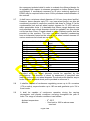
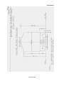
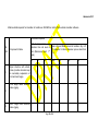
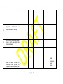
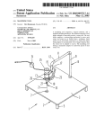
TECHNICAL SPECIFICATION OF MUCK DISPOSAL UNIT (1676MM GAUGE) (Specification No. TM/HM/MDU/Spc.01) 1.0 1.1 1.2 1.3 1.4 1.5 2.0 GENERAL After mechanized screening of ballast on Indian Railways, the muck/spoil is usually thrown on the slope of the formation through the waste conveyors of ballast cleaning machines (BCM or SBCM). However, the muck has to be necessarily collected in a muck disposal unit connected to the BCM/SBCM when screening ballast on multiple line sections or in cutting or in areas where space by the side of the track is limited. It is also essential for such muck disposal unit to be able to self unload itself into similar units coupled in series to ensure continuous working of the BCM/SBCM. It should be possible to discharge the muck into a wagon either on the adjacent track or on the same track or in a lorry by the side of the track or on the slope of formation as the case may be. This technical specification has been drafted to reflect the performance and quality requirements of such Muck Disposal units herein after called machine. These Specifications have been drafted to reflect the performance and quality requirements of the machine in a neutral manner without bias to any specific manufacturer. Bidders are requested to carefully study the specifications and assure that their equipment fully comply with these specifications. Thereafter, if a bidder feels that his machine can substantially meet the performance and quality requirements of the specification but does not fully satisfy a particular system specification, he should mention the same in the statement of deviation from the specification, giving the details how the functional requirement are going to be met with. The bidder shall specify the model offered and furnish a detailed technical description of the machine. System/sub-systems of the working mechanisms of the machine shall be as per para „3.0‟ in particular and all the items of specifications in general shall be described in detail with the sketches to show the manner in which the requirements of the specifications are accomplished by the machine (model) offered. The tenderer shall furnish a compact disc (computer enabled) or DVD or USB showing the working of machine under field conditions. Also,Photographs of the type of machine in working mode shall be enclosed with the offer. The photographs shall also show close-ups of various working assemblies/systems and the full machine. DIMENTIONAL AND OPERATING REQUIREMENT: Page 1 of 24 2.1 The Machine should be robust and suitable for working on Indian Railway broad gauge track. The design and dimensions of the machine components shall be to metric standards. Quality assurance during manufacturing of the machine shall be according to ISO-9001. The machine shall be suitable for working on straight, transition and curved track (up to 10°) on broad gauge (1676mm) of Indian Railways. 2.2 The profile of the machine longitudinally and in cross section during movement duly towed in train formation shall be within the maximum moving dimensions shown in the Indian Railways Standard BG schedule of Dimensions (metric)-2004 print and is enclosed as Annexure-I. The tenderer shall provide sketches of the machine in plan and shall give calculations for moving dimension on 10° curve to show the extent of lateral shift at the ends , centre and any other relevant cross section and to prove that the machine does not cause infringement while moving on a 10° curve at any cross section. 2.3 Where an infringement to Indian Railways Standard BG schedule of Dimensions (metric)-2004 print is considered necessary by the manufacturer as intrinsic to the design of the machine for meeting the work performance requirements laid down in this specification while meeting the safety and operational requirements of IR, the same shall be done with the prior approval of the Purchaser and decision of the Purchaser in permitting any such infringement shall be final and binding on the manufacturer. Tenderers may note that acceptance of any such deviation during consideration of preliminary design details in the offer is only in principle acceptance and the final decision will be taken by the Purchaser at the stage of consideration of machine design for issuing speed certificate. In the past IR have condoned certain infringements to such dimensions as Rigid wheel Base, Length of stocks, Distance apart of bogie centres and maximum height of floor above Rail level in certain track machines after due consideration of their design features vis-à-vis safety and operation requirements of IR. However, condonation of an infringement in another track machine in the past does not by itself entitle the manufacturer to assume acceptance of the same in other track machines by IR. 2.4 Adequate clearance shall be allowed so that no component infringes the minimum vertical clearance of 102 mm from rail level while travelling. 2.5 Axle load of the machine shall be lesser than 20.32 T t with minimum axle spacing of 1.83 m. Load per metre shall not exceed 7.67 t. Axle loads upto 22.82 tonnes and lower axle spacing may be permitted, provided the load combinations do not cause excessive stresses in the tracks & bridges of IR. Stresses in the tracks & bridges shall be calculated by IR/RDSO based on design data submitted by the firm as per (annexureIVA,B &C), and decision of IR/RDSO shall be final in this regard. 2.6 Normaly the stocks running on IR are two axled or three axle bogie stocks. For new combinations of axles/bogies the supplier shall submit Page 2 of 24 the necessary technical detail in order to evaluate the offerered design for its suitability with respect to stresses generated on Indian Railway track and Bridges. If considered necessary by IR prior technical approval of RDSO may be required before issue of the purchase order/finalization of the contract. 2.7 It shall have a minimum wheel diameter of 914 mm (new wheel profile). However, lesser diameter upto 730 mm (new wheel profile) can also be considered, provided it meets the condition laid down in Clause 2.3 at its condemnation limit and rail wheel contact stresses for 72 UTS rails are within permissible limits. It is desirable that 50mm margin between new and permitted worn wheel diameter should be available, but this should not be less than 20mm. Forged wheels to Indian Railways profile shall be provided on the machine. The worn out wheel diameter (condemning worn out diameter) based on the criteria of rail wheel contact stresses for various maximum axle loads are as under: Maximum Axle load (tonne) 22.82 22.00 21.50 21.00 20.32 20.0 19.5 19.0 18.5 18.0 17.5 17. 4 Minimum worn out wheel diameter (mm) 908 878 860 841 816 805 787 768 750 732 713 710 Permitted worn out wheel diameter should be specified by the manufacturer. The diameter of wheel for assesment of permitted axle load will be the worn out wheel diameter.The wheel profile shall be as per Indian Railway standard wheel profile provided in annexure-V. 2.8 It shall be capable of continuous negotiating curves up to 10o curvature (176 m radius), super elevation up to 185 mm and gradients up to 3% in travel mode. 2.9 It shall be capable of continuous operation during the varying atmospheric and climatic conditions occurring throughout the year in India. The range of climatic conditions is as follows:Ambient temperature Altitude : 0o - 55°C : Sea level to 1800 m above mean sea level Page 3 of 24 Humidity Maximum rail temp. : 40% to 100% : 70 o C 2.10 It shall be capable of working without requiring power block in electrified sections. On Indian Railways, 25 KV power is used for traction through an overhead wire at 5.5 m above rail level. On bridges and tunnels, the height is restricted to 4.8 m. 2.11 The machine or its any part shall not infringe the adjoining track as per „BG Schedule of dimensions of Indian Railways (metric)-2004 print with latest corrigendum and up to date correction slips issued while opening and closing of work. The machine shall be equipped with pneumatically operated brake blocks acting on all wheels. It shall be possible to haul the machine in both directions at the same speed. 2.12 In the work mode, no part of the machine should rise beyond 4.265 m. above rail level for safe working in the electrified sections. 2.13 While working on double line/multiple lines, it should not infringe the adjoining tracks and it should be possible to permit train at full speed on other tracks except when the muck conveyor is in inclined position to discharge muck on the sides. Minimum spacing between tracks is 4265mm. 2.14 During movement from one station to another in a train formation, it shall be capable of being hauled at a speed of 60 kmph 3.0 WORKING MECHANISM: 3.1 The muck disposal unit shall be capable of discharging waste like muck, ballast, sand, cinder etc. into another such unit attached to it in front or into another wagon or storing it for subsequent disposal. 3.2 It should be capable of unloading the material at any suitable discharging place without any auxiliary aids. 3.3 It should be able to work on single and/or double line track as well as between station platforms. 3.4 The continuous and complete loading should be possible by a longitudinal bottom conveyor belt at the floor of the machine. 3.5 It should be capable of unloading/discharging complete material by an inclined swiveling conveyor belt located at the front end of the machine. Page 4 of 24 3.6 It should be possible to unload/discharge the material on either side of the track beyond cess at a distance of not less than 5 meter from the centre of the track into a Railway wagon or a lorry/Truck by the side of Railway Line. 3.7 While working in series, it should be possible to unload all units simultaneously or to unload all units only through the leading units by transferring the material from one unit to the other. 3.8 The capacity of muck disposal unit should not be less than 65 m 3. The pay load it can carry should not be less than 95 tonne. A fully filled unit should be capable of fully self unloading in 10 to 15 minutes time. Tenderer should furnish details of dimensions along with calculation to show the carrying capacity of the machine. 3.9 Marking on inside face of the MDU indicating filled up volume of 50 cum, 55 cum, 60 cum and 65 cum for guidance of the field officials to load material upto different volume depending on bulk unit weight of material for ensuring total pay load to be within permissible limits. For indication of whether the vehicle has already been loaded to its full pay load capacity, a suitable system shall be provided which should indicate the weight of the pay load at any point of time along with suitable danger mark at the design pay load capacity. 3.10 Belt speed of conveyors should be adjustable. Muck dripping from the waste conveyor of BCM/SBCM should be dispersed evenly using floor conveyors or any other suitable mechanism on the machine so that uninterrupted working of Ballast Cleaning Machine/Shoulder Ballast Cleaning Machine is possible. 3.11 Suitable safety mechanism should be provided to ensure that the swiveling conveyor does not hit the OHE traction mast or signal post causing damage to it or to the machine. 3.12 It should have independent power source i.e. Diesel engine for working its own system except for haulage. The diesel engine should be installed in a covered area to protect it from bad weather, dust and rain. 3.13 The tenderer may be required to show the working of his machine under field conditions. The names of countries where such demonstrations will be feasible shall be indicated in the offer. 4.0 DIESEL ENGINE: Page 5 of 24 4.1 The machine should be powered by diesel engine with proven record of service in tropical countries and wide service network in India. Adequate allowance should be made for de rating of the diesel under most adverse climatic conditions. The engine should be able to unload the fully loaded muck disposal unit in ten to fifteen minutes at 70% rated capacity. 4.2 The supplier should furnish the information regarding make and model of the engine proposed to be used and details of agency which will provide after sales service support and availability of spares in India. 4.3 High speed diesel oil to Indian Standard Specification shall be normally used. Sufficient fuel storage for continuous operation for minimum eight hours shall be provided. 4.4 Sight glass type fuel measuring gauge shall be provided on the fuel tank. 4.5 For starting the engine, storage batteries of well-known make with wide service network in India shall be provided. 4.6 Since the engine is to work outdoor under extreme dusty conditions, the air intake system shall be designed suitably so as not to allow dust through air intake system. 4.7 There is a likelihood of dust deposition over the engine body and surrounding area over the lubricants spills over. These should be easy to access for daily cleaning and routine maintenance. In case, air cooled engines are proposed by the supplier, maintenance equipment for cleaning and maintenance of the air cooling fins shall be provided by the supplier along with the machine. 4.8 The engine parameter monitoring gauges like temperature, rpm, and lube Oil pressure shall be direct reading type mounted on the engine backed up by electrical/mechanical/Electronic gauges/display system in the operator‟s panel showing the absolute readings along with safe limits suitably coloured. There shall be audio visual warning (safety mechanism) to the operators in case of any of the parameters exceeding the safe limit and engine shut down circuit in case of operator‟s failure to respond. 4.9 Suitable and rugged mechanism should be provided to start the prime mover at no load and gradual loading after the start of the prime mover. The engine power take off shall be coupled to the main gearbox through a flexible coupling. The engine shall be mounted on suitable Anti-Vibration Mountings. 5.0 HORN AND CONTROL PANEL: 5.1 The machine should be provided with electric/pneumatic horn at suitable location to warn the workmen of any impending danger at the work spot, distinctly audible from a distance of at least 400 meters from the machine. The horn should be operated by means of push button provided on the Page 6 of 24 body of the machines at suitable locations and also from all portable control panel connected by flexible cable to the machine. The portable control panel should also have control switches for the operation of bottom and swiveling conveyors. 5.2 Machine shall be provided with emergency backup system to retract the disposal conveyor to its normal position in the event of failure of prime mover or power transmission system of the machine. 6.0 LIGHTING: The machine should be equipped with swiveling lights at both the ends for movement and for lighting the working area, working unit during night working. Also it should have two front and rear parking lights, which can be switched to red or white according to the direction of the travel at each end. 7.0 BRAKES 7.1 The machine shall be fitted with the compressed air brakes system applying brakes equally on all wheels. The brakes shall be protected from ingress of water, grease, oil or other substances which may have an adverse effect on them. The brake lining shall be suitable for high ambient temperature of 55C. In addition, mechanical brakes shall also be provided for use in an eventuality of failure as well as for parking. 7.2 Machine shall be equipped with suitable air brake valves so that while working in train formation, machine can be broken by the traction vehicle. 8.0 HOOKS AND BUFFERS: The machine shall be fitted with transition centre buffer couplers on both ends for attaching it with other vehicle for running in train formations. Attachment with IR standard locomotives, wagons & coaches should be possible. 9.0 CHASSIS AND UNDERFRAME The chassis shall be of standard welded steel sections and of steel sheets, so as to permit transportation of the machine in train formation without endangering safety of the train. The under frame shall be constructed with rolled steel section and/ or plates shall be designed to withstand a maximum static squeeze test load test of 102t at buffers i.e. 51t at each buffing point without any permanent distortion. The under frame shall be sufficiently robust for safe travel of the machine in train formation and not necessarily as the last vehicle. 10.0 TOOLS AND INSTRUCTION MANUALS Page 7 of 24 10.1 Each machine should be supplied with a complete kit of tools required by the operator in emergency and for normal working of the machine. The list of tool to be provided should also include all the tools necessary for the maintenance and repair of entire machine including specialized equipment. All special tools should be listed and cataloged illustrating the method of application. The list can be modified to suit the purchaser‟s requirement, while examining the offer 10.2 Detailed operating manual, maintenance and service manual should be specifically prepared in English language and four copies of these should be supplied with each machine. 10.3 The supplier shall also supply circuit diagrams of electrical, hydraulic, pneumatic and electronic circuits used on the machine. Trouble shooting diagram/table shall also be supplied. In additions, the supplier shall provide dimensional drawings with material description of items like rubber seals, washers, springs, bushes, metallic pins etc. Main features such as type, rpm & discharge etc of items like hydraulic pumps-motors and such other brought out components/assemblies shall be furnished by the supplier. The aforesaid details shall be supplied to the extent available with the manufacturer. These shall be specially prepared in English language and four copies of these shall be supplied with each machine. 10.4 The tenderer shall along with his offer submit the list of tools, manuals, circuit diagrams and other technical literature/drawings to be supplied along with each machine as above, for operation, servicing, maintenance and trouble shooting, along with his offer. The list can be modified to suit the purchaser‟s requirement, while examining the offer. 10.5 While offering the machine for first inspection, the supplier shall submit one copy of complete technical literature in English language including operation, service and field maintenance manuals/instructions and complete electrical, hydraulic and pneumatic circuit diagrams, trouble shooting charts, component drawings/ description and other relevant technical details as a reference documents for the inspecting officer. 10.6 One set of all the manuals and diagrams should be sent to the Principal/IRTMTC, Allahabad, one set to ED/TM, RDSO, Lucknow, one set to DTK(MC)/ Railway Board and one set to Director/IRICEN/Pune alongwith supply of first machine. In case there is any subsequent amendment in above documents based on field performance, the Page 8 of 24 amendment/amended documents should also be sent to above mentioned authorities. 10.7 The firm shall provide detailed technical drawings and specifications of wheels and axles used on the machine. The above details shall be provided in four sets with each machine. 10.8 A draft copy of all documents to be supplied with the machine should be sent 3 months in advance of inspection of the first machine to RDSO for their review regarding adequacy and manner of detailing. Necessary modifications and further detailing as per RDSO‟s comments should be carried out and compliance should be reported to RDSO as well as the Inspecting officer of the first machine. 11.0 OPERATORS: The number of operators and allied staff for working of machine under normal condition should be indicated, specifying their duties and minimum qualifications. 12.0 SPARE PARTS: 12.1 The expected life of the components should be advised along with their condemning limits. The machine should be supplied with necessary spare parts for the operation and maintenance of the machine for a period of two years i.e. working for about 2000 hrs. The spare parts required should be detailed in a separate list including description, part no, quantity and whether imported or indigenous. The manufacturers should be responsible for the subsequent availability of spare parts to insured trouble free service for the life of the machines (15 years). 13.0 OPTIONAL EQUIPMENT Tenderer is expected to quote for optional equipment if any separately for each items giving the advantages/ functions of such optional equipment. Tenderer shall also indicate whether such equipment is already in use on machine elsewhere indicating the user railway system. 14.0 14.1 Inspection of the Machine: While inspecting the machine before dispatch from the supplier‟s premises, the inspecting officer shall verify the conformity of the machine with respect to individual specification as above. The machine‟s conformity/non-conformity issue in respect to each item shall Page 9 of 24 be jointly recorded before issue of the inspection certificate and approval for dispatch of the machine as per Annexure–III enclosed. 14.2 Following arrangements shall be made by the supplier/Manufacturer at the inspection premises for carrying out inspection of the machine by inspecting officials: Machine to be stabled on straight & level BG track. The length of the track should be at least 10 m more than buffer to buffer length of machine. In order to check Maximum Moving dimensions in cross section, a Sturdy frame of IR Max Moving Dimensions shall be provided by the manufacturer and passed over the machine holding it perpendicular to track, centre aligned with track centre. Adequate arrangements shall be made to the satisfaction of inspecting official. 14.3 The following documents shall be provided to the Inspecting Officer at least 4 weeks in advance of the date of inspection. i) One copy of complete technical literature mentioned in clause 10, in English language, including operation, service and field maintenance manuals/instructions and complete electrical, hydraulic and pneumatic circuit diagrams, trouble shooting charts, component drawings/ description and other relevant technical details as a reference documents for the inspecting officer. ii) Cross section of the machine super imposed on IR maximum moving dimensions envelope shall be provided to IO in advance. iii) Clause by clause comments of the manufacturer to be sent to Inspecting Officer (IO) in advance for his review. Comments should state manufacturer‟s conformity of compliance of each of the requirement stated in each clause, elaborating where necessary the details/manner in which the requirement has been complied. The proforma for the clause-wise comments is given below: Clause No. Clause Comments of Supplier/manufacturer Comments of Inspecting Officer iv) Manufacturer‟s Internal Quality Inspection Report of the machine. v) Manufacturer‟s quality certificate and/or test reports for bought out assemblies/sub-assemblies to be provided to IO, containing serial number wherever applicable. vi) Draft Inspection Report to be prepared by the manufacturer, containing all annexure mentioned at para 14.4 vii) Details of arrangements made for checking Maximum Moving Dimensions for his approval. Page 10 of 24 Supplier will incorporate amendments/further clarification in the above documents to the satisfaction of the Inspecting Officer keeping in view the Inspecting Officer‟s comments, if any. 14.4 List of documents to be annexed in the draft Inspection Report should include: i. Maker‟s Test Certificate. ii. Manufacturer‟s Internal Quality Inspection Report iii. Quality Certificates of Bought out assemblies/sub-assemblies iv. Cross section of the machine super imposed on the IR MMD v. Vogel‟s diagram vi. List of spare parts to be dispatched along with the machine vii. List of tools to be dispatched along with the machine viii. List of. Manuals, Drawings, Spare Parts Catalogues, etc. to be dispatched along with the machine, duly indicating the number of sets of each. These above documents shall be part of final inspection report 15.0 16.0 Warranty: In addition to the special condition of contract dealing with warranty the following will apply. The machine shall be warranted for 1200 effective working hours or 18 months from the date of commissioning and proving test of equipment or 24 months after delivery at ultimate destination in India which ever shall be earlier. Effective working hours will be total engine hours which the machine/unit is put to work for collection/disposal of muck/spoil. Should any design modification be made in any part of the equipment offered, the period of 18 months would commence from the date of the modified part is commissioned in service for the purpose of that part and those parts which may get damaged due to defects in the new replaced part. The cost of such modification should be borne by the supplier. Issue of Provisional Speed certificate Whenever a new rolling stock is introduced in Indian Railways, a provisional speed certificate is issued by RDSO based on certain design parameters of the vehicle. Final speed clearance of the vehicle is given after conducting detailed oscillation trial of the vehicle, which is a time taking process. Therefore, issue of provisional speed certificate for the vehicle becomes a necessity and based on the same the approval of running of the vehicle on Indian Railway track is taken from Commissioner of Railway Safety. For issue of provisional speed certificate, the following actions are required to be taken by the suppliers. a) Current suppliers, whose models are approved: The supplier shall give details of the model, year of introduction in Indian Railway, details of speed certificate issued etc. The supplier shall certify that no change has taken place in the model being offered with respect to design of under carriage i.e. suspension system/arrangement, wheel & axle assembly, bogie, braking Page 11 of 24 arrangement loading pattern of the vehicle etc. and the distribution of axle loads, lateral forces, unsprung mass and braking force coming on rail is the same. If, there is any change in above respect, the action shall be taken as detailed in para (b) below: b) c) 17.0 Current suppliers, whose models are not approved / or new: As soon as the supplier completes the design of the machine as per specifications, the technical details as per Annexure (IVA, IVB & IVC ) shall be supplied for processing of provisional speed certificate for the machine so that it can be permitted to move on track. On case-to-case basis, more technical details (other than mentioned in Annexure IVA, IVB & IVC) may also be required for issue of provisional speed certificate for the machine. New suppliers, whose models are new: The technical details shall be supplied as detailed in para (b) above. MAKER’S TEST CETIFECATES: Copies of maker‟s certificate guaranteeing the performance of the machine should be supplied in duplicate along with the delivery of each machine. 18.0 MARKING & COLOUR OF MACHINE : 18.1 The machine body shall be painted in golden yellow colour, conforming to RDSO specification No M & C/PCN/109/88 (with latest amendment) to minimum DFT of 80 mm. Colour code to be ISC: 356. 18.2 Following should be written on the machine at appropriate location i) India Railways logo of height between 300 mm to 600 mm as suitable on all four faces of the machine. ii) On both side faces, below the Indian Railways logo, the text “ INDIAN RAILWAYS” to be written in Bold and in Black colour of size equal to or slightly smaller than the size of logo but of size not less than 250 mm. iii) Below the text “INDIAN RAILWAYS” mentioned above, Machine model and manufacturing Year should be written in black colour and in letter of size less than the size in which Indian Railways is written but not less than 200 mm in any case. iv) If the Manufacturers desire to write their name on the exterior of the machine, the same may be written in size not more than 150 mm and should not be at more than four locations. The Manufacturers Logo may be provided at not more than four Locations on the exterior of the machine and should be of size not more than 200mm. 19.0 ACCEPTANCE TEST: Page 12 of 24 19.1 19.2 19.3 19.4 19.5 19.6 19.7 19.8 20.0 In addition to verification of the various items of specifications covered earlier, the following tests should be carried out in the purchaser‟s premises by the purchaser‟s nominee at the time of commissioning of the machine. Dimensional check of loading gauge i.e. maximum moving dimensions, buffer heights, bogie distance, length of machine and clearances at curves etc. Engineering and construction of the machine. Testing for negotiability of 100 curve and 1 in 8-1/2 turnouts for the first machine. Running speed test on the Indian Railways main line will carried out as per Annexure-II on the first machine. The capacity of muck disposal unit by dimensional measurements to comply with minimum requirements mentioned in para 3.8 described above, on the first machine. The conveying output of Muck Disposal Unit by completely unloading a fully loaded unit, to comply with minimum requirements mentioned in para 3.8 described above, on the first machine. Capability of muck disposal unit to unload/discharge the material on either side of the track beyond cess at a distance of 5 meters from centre line of track, on the first machine. Actual output and performance tests – Refer Clause 3.0 above : The general conditions of the tests shall be as follows: a) Machine crew shall be either trained personnel of Indian Railways or the staff of the supplier. b) Dry weather, ambient temperature between 0 to 55 C . c) Straight track or curve with radius not less than 1000 m. Gradient upto 1/ 200 21.0 22.0 The setting up time and winding up time of the machine shall be measured and the total time taken by the two operations of setting up and winding up of the machine together shall not exceed 20 minutes. Should any modification be found necessary as a result of the test these should be carried out by the supplier at his own expenses? Page 13 of 24 Annexure-1 Page 14 of 24 ANNEXURE-II 1. The speed potential of the machine offered by the firm should be established based upon oscillation trials conducted in India. The tests will be conducted at speed usually 10% higher than the maximum speed potential indicated by the firm for the machine under consideration and the following criteria satisfy for the same. For conducting the tests, a section of mainline track will be selected over which there is no temporary speed restrictions and which is considered by the Railway as being in a generally run down condition for mainline standards, but without speed restrictions. The vehicle will be tested generally for new and worn clearance conditions and where relevant for operation in the forward and backward directions. The vehicle selected for tests will be one in average condition for normal maintenance. 2. The criteria applicable for establishing speed potential will be as follows: A lateral force lasting more than 2 metres should not exceed the PrudHomme‟s limit of 0.85 (1 + P/3) where P is the axle load. Isolated peak values exceeding the above limit are permissible provided the record shows establishing characteristics of the vehicle subsequent to the disturbances. A derailment coefficient should be worked out in the form of ratio between the lateral force (hy) and the wheel load (Q) continuously over a period of 1/20th second, the value HY/Q shall not exceed 1. The values of acceleration recorded in the cab at location as near as possible to the bogie pivot (as near as possible to axle in case of four wheelers) shall be limited to 0.55 kg both in vertical and lateral directions. The peak values upto 0.6 g may be permitted if the records do not indicate a resonant tendency in the region of peak value. In the case of such vehicles where measurement of forces is not possible, the evaluation shall be in terms of ride index based on the accelerations measured as detailed in Para 2 (iv) above which shall not be greater than 4.5 but a limit of 4.25 is preferred. A general indication of stable running characteristics of the vehicle as evidenced by the movements of the bogie in straight and curved track and lateral force and derailment coefficient of accelerations as the case may be. i) ii) iii) iv) v) vi) Page 15 of 24 ANNEXURE- III INSPECTION CERTIFICATE CERTIFICATE OF INSPECTION OF TRACK MACHINE ( ) BY INSPECTING OFFICIAL AND APPROVAL FOR DESPATCH OF MACHINES. (STRIKE OUT WHICHEVER NOT APPLICABLE) This is to certify that I have inspected the machine (type)_______________________________bearing Sl.No._________________ from (date) ____________to _____________at (Place) ________________ for its conformity/non-conformity with respect to the laid down Technical Specifications in contract Agreement No.________________________________ dated_______________________between President of India through Director Track (Machines) and M/s. (Name of Supplier) ___________________________ ___________________________________. The detailed Inspection Note regarding its conformity/non-conformity to the laid specifications is enclosed along with as Annexure „A‟. It is observed that (strike out whichever is not applicable): The Machine conforms to all the laid down specifications. The machine conforms to all the laid down specifications except those at Sl.No.________________________. The above deviations are minor/major affecting/not affecting the performance of the equipment in substantial way. The following T and P/manuals/drawings are to be supplied alongwith the machine: 1. __________________________ 2. __________________________ 3. __________________________ Based on the above, the Machine is certified/not certified to be conforming to the specifications. The machine is approved/not approved for despatch to _____________ ________________(Consignee) Indian Railway. SIGNATURE AND DATE For M/s.__________________ INSPECTING OFFICIAL _________________________ (NAME AND DESIGNATION) for and on Behalf of President of India Page 16 of 24 Annexure : IV A 1. a) b) 2. 3. 4. 5. 6. Particulars Required in Respect of the Rolling Stock Under Consideration A diagram showing elevation salient dimensions : Wheel spacing, Wheel diameter, bogie centres, and axle load. i) Over all length of the vehicle : ii) Length over head stock : iii) Length over buffers : iv) Distance apart for Centre of buffers : v) Max./Min. height of centers of buffers above rail level : i) Wheel base : ii) Axle load (max) : iii) Bogie Centres : Wheel dimension i) New ii) Worn out i) Tread and flange profile of the wheel indicating clearly whether it is Indian Railway standard profile or differs from standard flange profile. ii) Wheel gauge dimension – (back to back of tyre flange). : : Whether the stock is designed to be used as a general purpose or in a closed circuit in specified sections under defined conditions. Maximum design speed : i) Own Power : ii) In train formation : : : : Unsprung weight per axle in tonnes i) Driving axle : ii) : Running axle 7. Expected lateral force in tonnes per axle At maximum design speed. 8. Method of operation : Whether single only or coupling together is possible. If coupling is possible, the number which can be coupled and what is trailing load. Page 17 of 24 : 9. Maximum tractive effort at start and at the speed of operation i) ii) 10. at working drive at transfer drive at start : at operation speed : at start : at maximum speed : Maximum braking force coming on to the rails per wheel a) b) at working axle at transfer axle : : 11. Drawing indicating suspension arrangement details of bogie and axle. : 12. Height of centre of gravity from rail level : 13. Height of floor from rail level 14. Type of coupler provided -Indian Railways Standard : Coupling Buffer 15. Any infringement to the moving dimensions Sketch provided in the Indian Railways Standard Schedule of Dimensions – Chapter IV (A). Page 18 of 24 : : : Annexure : IV B Following information as detailed below is also required along with the information required as per Annexure ‟A‟ for processing the case for issue of provisional speed certificate for new vehicle S.no Item 1. a) b) Brake System details Gross Braking Ratio 2. Brake rigging arrangement drawing and calculation of braking force 3. Maximum Braking Effort. at start and at the speed of operation a) at working drive at start : at operation speed : b) at transfer drive at start : at maximum speed : Characteristics of springs used in suspension indicating free height, working height, dynamic range, stiffness and locations etc. 4. 5. 6. Characteristics of the dampers if used, and over all damping factors and locations of dampers. Calculation of the following frequency of the vehicle to be attached :i) Bouncing ii) Pitching iii) Rolling Wave length of free axle and bogie Write up and salient design calculation on suspension system, type of suspension- whether it is of coil suspension with or without dampers and laminated bearing springs and double link suspension. 7. What are lateral clearance of axle box / horn, wheel flange/rail and other locations for the negotiability of the vehicle on curve and turn out (enclose Vogels Diagram for negotiability on maximum degree of curve and turn out permitted on Indian Railways) of new and worn out wheel. 8. Wheel and axle assembly drawings 9. Calculation for flange force 10. Technical specifications of Vehicle supplied. 11. Calculation of natural frequency 12. Calculation of spring characteristics and critical speed of the vehicle. 13. Simulation result showing ride index, lateral force and acceleration results. 14. A certificate regarding the speed of the vehicle for which it has been designed. Page 19 of 24 Annexure IV-C Machine details required for simulation of machine on NUCARS or similar Track-vehicle simulation software Parameters required SL. NO. Component‟s Name C.G. of component in x,y,z Mass in Kg and Mass moment of inertias in Kg- m^2 direction from rail level in of component in three dimension space about their mm (Referenced point 1st C.G axle ) X 1. Y Z Mass Super structure with vehicle frame (machine structure kept on secondary suspension of front and rear bogie) Front Bogie frame including brake rigging 2. 3. Rear Bogie frame including brake rigging Page 20 of 24 Ixx Iyy Izz 4. 5. Transmission system device (hydraulic. Mechanical or electrical traction motors) Wheel axle set including axle boxes which constitute the unsprung mass Mass of Items included in unsprung mass partially or 1 fully along with their name per 2 3 4 Page 21 of 24 5 6 Total unsprung mass in tonnes 6. axle Front bogie assembly 7. full Full weight of vehicle Rear bogie Machine full frame full (front bogie + rear bogie +vehicle assembly structure car body or super structure) Total weight of components in tonnes Primary suspension element Secondary suspension element stiffness per Suspension stiffness details stiffness per axle box between side between bogie and machine frame bogie and axle box in Kg/mm 8. Vertical stiff Lateral stiff Longitudi nal stiff Vertical stiff 9. ( If hydraulic damper used give there rating force per meter/second) 10. Clearance in mm or radian Vertical provided for motion between Lateral Longitudi nal Rotation Rotation Rotation about about vertical about lateral longitudinal Lateral stiff Longitudinal stiff Damping force details Page 22 of 24 bogie frame and machine direction frame for relative motion (motion stopper) of direction direction axis axis axis Detail of location of suspension Detail of location of suspension springs and springs and dampers and shock dampers and shock absorbers with support absorbers with support drawing drawing 11. Dimension of location suspension elements 12. Details of arrangement location 13. Concerning with general arrangement of vehicle, bogie general arrangement, Set of drawings and design suspension arrangement details, suspension clearances drawing, detail written description description of configuration and loading pattern accompanies design particular of vehicle bogie. centre pivot working and Provide detail arrangement drawing and description Page 23 of 24 Annexure-V Page 24 of 24