1
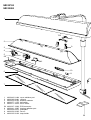
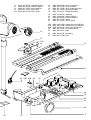
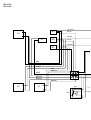
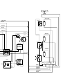
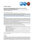
HPA solarium
HB 821/A
HB 824/A
Service
Service
Service
!
Service
Information
!
Service
Information
Domestic Appliances and Personal Care
Service Manual
TECHNICAL DATA
Input consumption
UV-A source
Ballast
Starter
Timer
Hours counter HB 824
Radiation area
Protecting goggles
Output (minimum)
LMV meter
HEBRU meter
Production code YYWW
L
1200W / 230V
3x HPA400 / 118 mm
3x BHA 400L / 230V
3x SN 58-spec.
60 mins motor driven
electro mechanical
185 x 75 cm
HB072 - 4822 690 80147
mW/cm at 65 cm
4.6
2.4
on type plate
:
:
:
:
:
:
:
:
:
:
:
:
FLOOR PART
SK1
Re1
b1
a1
C1
M
L1
L2
L3
S1
S2
S3
SK2
a
HB 824
TIMER
H
SK3
N
M
LA1
SK4
LA2
SK5
LA3
TCO
RADIATION PART
Published by Philips Domestic Appliances and Personal Care
4822 729 21954
98/05
PCS 98 527
Printed in The Netherlands
©
Copyright reserved
Subject to modification
IMPORTANT
HINTS FOR REPAIRS
-
On account of the short high starting current, the
house fuse should be of a 16A-delayed type.
-
If the lift mechanism is defective or the wiring between
floor part and radiation part is interrupted, you should
contact a Philips Service Centre (repair is not possible).
-
The appliance will work in operating position only.
-
-
Always check if the protecting glass pane (item 7) is
fitted after a repair.
The above also applies when the housing (item 1) has
to be replaced.
-
HPA-lamps only start when they have cooled down
sufficiently.
-
Never touch a HPA-lamp with your fingers.
If necessary, clean the lamp with alcohol.
Disassembly of the radiation part:
1. Remove the 10 screws with wich the cover
(item 6) is fastened to the housing (item 1).
The cover will continue to cling to the housing.
2. Disconnect the connectors of the connecting cable
and motor.
3. Undo the other connections.
-
Colour differences may occur when new lamps are
installed. This phenomenon is characteristic of HPAlamps and disappears after a short period of use.
-
It can be established whether lamps, ballasts or
starters are defective by interchanging them.
-
After assembly the glass filter should be free from
finger prints and dust.
Clean the glass filter with alcohol, if necessary.
-
When replacing a lamp holder (item 9) 2 tubular rivets
must be drilled out.
The bracket is fastened with 2 M2.5x10 bolts.
-
Never look in the direction of the radiation part while
the lamps are on without wearing protecting goggles.
-
-
In case of insufficient cooling (e.g. when the
ventilation apertures are blocked or when the fan is
defective) the safety device (item 8) will automatically
switch off the solarium.
Once the cause of overheating has been removed and
the solarium has cooled down sufficiently, the
appliance will switch on again automatically.
-
When the appliance is a few years old, we advise you
to apply a drop of thin oil to the bearings of the fan.
Disassembly of the floor part:
1. Remove 6 square and 3 round ornamental props
(item 16).
2. Loosen 14 visible screws by which the cover
(item 15) is fastened.
3. Pass the mains cord cover (item 23A) and the
timer cover (item 13A) through the opening
below, after the screws have been taken out.
4. Loosen the screw under the timer cover.
5. Remove the cover (item 15) in horizontal position
so that the screws will not fall out.
(As screws with varying length are used, it is not
possible to interchange them.)
-
Let the solarium cool down first (approx. 15 mins)
before closing and storing it away.
-
The wheel can be replaced after the decorative cap has
been removed by means of a small screwdriver.
-
Only move the solarium when folded.
-
In case of complaints about little or no tanning, the
output can be measured by means of a so-called LMVor HEBRU-meter.
The figures given on the tittle sheet are the minimum
values to be measured in the centre of the radiation
field after 5 mins of warming up and with the
appliance connected to the rated voltage.
PCS 66230
PCS 98 528
HB 821/A
HB 824/A
1
TCO
8
LA1
2
LA2
3
4
5
5A
9
LA3
SK4
SK5
10
6
11
7
1
2
3
4
5
4822 442 01444
4822 380 20441
4822 452 80162
4822 277 11375
4822 271 30619
cover radiation part
reflector
distance indicator
ball switch
micro switch
5A
6
7
8
9
4822 267 10902
4822 441 12207
4822 466 62573
4822 252 20325
4822 325 20102
PCB connector
housing radiation part
glasspane
cut-out
lamp holder
26
10
11
12
13
13A
4822 134 30032
4822 492 90188
4822 361 21555
4822 413 51453
4822 442 01445
HPA400W lamp
reflector clamp
motor with fan
timer knob
timer cover
12
14
15
16
17
18
4822 349 40068
4822 442 01443
4822 462 11095
4822 441 12206
4822 142 60417
timer 60 minutes
cover floorpart
set of ornament props
housing floorpart
ballast 220-240V
19
20
21
22
23
4822 124 40701
4822 219 80605
4822 265 20234
4822 528 11272
4822 321 10887
capacitor
starter SN58/S
mains connector
wheel
flex EU black
23A
23A
23B
24
25
4822 442 01449
4822 442 01686
4822 344 40197
4822 265 31006
4822 280 60513
mainscord cover HB 821
mainscord cover HB 824
hours counter HB 824
connecting block
relay
26
27
4822 492 90187 flat spring
4822 402 10789 lever
13
13A
14
15
SK2
16
23 23A 23B 24
25
17
L2
L1
SK1
L3
1
S
2
S
3
S
18
19
20
21
SK3
22
26
27
5
HB 821/A
HB 824/A
YELLOW
S3
L3
BLUE
WHITE
C1
S2
BLUE
GREEN
S1
RED
YELLOW
RED
WHITE
RED
GREEN
N
BLUE
BROWN
BROWN
BROWN
L
BROWN
L2
Re1
L1
SK1
b1
11
a
b
14
a1
M
YELLOW
YELLOW
TCO
BLUE
La
3
WHITE
BLUE
GREEN
BLUE
N
WHITE
RED
L
La
2
SK3
SK5
HB 824
HOURS
COUNTER
GREEN
N
BROWN
L
SK4
La
1
TIMER
Re1
SK1
b1
11
a
b
14
M
(N)
a1
SK2
a
RED
BROWN
GREEN
WHITE
YELLOW
BLUE
L
1 2 3
N