1
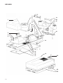
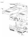
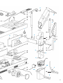
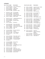
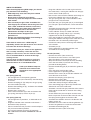
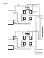
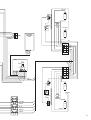
HPA Solarium
HB 846/A
Philips Domestic Appliances and Personal Care
Service Manual
TECHNICAL DATA:
Input Voltage
Input consumption
UV-A source
Ballast
:
:
:
:
230 V / 50 Hz
approx. 1800 W
4x HPA flexpower 400-600
4x BHA400L
Starter
Timer
Radiation area
Output (min) UVX-36 meter
:
:
:
:
4x SN58-spec.
Digital 29 min.
190 x 75 cm
3.9 mW/cm2 at 70 cm
FLOOR PART
SK1
PCB
L
D
T
D
NTC
1
NTC
2
NTC
3
NTC
4
L1
L2
L3
L4
TS
C
D
S1
S2
C1
S3
C2
S4
C3
C4
D
IC
C
LA1
LA2
M1
LA3
LA4
M2
µC
Buz
SK
SK3
REMOTE CONTROL UNIT
TCO1
RADIATION PART
SK4
TCO2
SK6
RADIATION PART
N
Published by Philips Domestic Appliances and Personal Care
4322 277 00967
02/07
Printed in the Netherlands
© Copyright reserved
Subject to modification
HB 846/A
5
1
6
19
7
20
8
21
9
10
11
12
23
2
3
4
18
13
14
15
16
17
24
29
32
33
2-5
HB 846/A
35
25
36
26
22
37
G
27
28
30
31
38
39
40
34
41
42
D
53
43
44
A
45
46
47
37
C
L
54
H
G
55
F
56
B
48
57
K
49
50
58
K
N
59
M2
51
52
O
M1
60
E
3-5
HB 846/A
Item Service code
Description
1
2
3
4
5
4222 062 95470
4822 417 30163
4822 325 20102
4822 380 20306
4822 417 11009
Cover radiation part
Lock left
Lamp holder
Reflector
Stop disc + roller
6
7
8
9
10
4822 361 11186
4822 532 40186
4822 265 41388
4822 532 10744
4822 271 30619
Fan complete
Retaining ring
PCB connector
Speed clamp 3.6 mm
Micro switch
11
12
13
14
15
4822 441 12212
4822 282 40255
4822 404 40639
See item 10
4822 410 40417
Lamphousing flex-side
Aut. cut-out
Switch bracket
16
17
18
19
4822 466 61869
4822 466 62476
4822 134 30032
4822 411 90032
4822 498 10706
Glass plate white
Glass plate brown
HPA flex power 400-600
Hinge cap
Grip
20
21
22
23
24
4222 062 95020
4822 441 12213
4822 462 11099
4822 442 01454
See item 1
Distance indicator
T-piece
Orn. prop (set)
Cover T-piece
25
26
27
28
29
4822 442 01448
4822 442 01452
4822 219 80605
4222 062 94570
See item 8
Flex holder (mains)
Cover flex side
Starter SN58-spec
Connecting block
30
31
32
33
34
4222 062 94580
4822 404 40554
4822 417 30164
4822 441 12211
4822 535 10561
NTC resistor
Holder
Lock right
Lamphousing RC-side
Bar grip
35
36
37
38
39
4822 321 11395
4822 256 10495
4822 320 12291
4822 265 20234
4222 062 94330
Flex EU
Flex holder (timer)
Remote control cable
Connecting block 2S
Ballast 230 V
4-5
Switch pin
Item Service code
Description
40
41
42
43
44
4822 124 40701
4822 528 70519
4822 441 12209
4822 404 40654
4222 062 95480
Capacitor 25 µF / 250 V
Wheel + spindle
Housing floor part
Holder
Remote control
45
46
47
48
49
4822 529 10255
4822 410 11892
4822 442 01455
4822 146 20823
4822 218 11844
Gas spring base
Memo knob
Cover RC-side
Transformer
PCB complete 230 V
50
51
52
53
54
4822 265 20655
4822 528 11272
4822 410 11893
4822 462 11098
4222 062 94680
Connecting block 7S
Wheel complete
Ornamental screw
Cap spring fix
Gas spring (hinge)
55
56
57
58
59
4822 498 10707
4822 442 01457
4822 530 70444
4822 442 01453
4822 417 50288
Grip part complete
Cover gas spring
Spring fix 85X26
Hinge cover
Lift mechanism
60
--
4822 404 40725
4822 690 80123
----
4822 395 50446
4822 310 31791
4822 321 11413
Guide pin
HB 071 protecting
goggles
Set of keys
Damping material
Coiled flex 7C
HINTS FOR REPAIRS
When checking/replacing HPA-lamps you should
pay attention to the following:
• HPA lamps only start when they have cooled
down sufficiently.
• Never touch a lamp with your fingers.
If necessary, clean the lamp with a cloth soaked
with alcohol.
• After assembly the glass filter should be free
from finger prints and dust. Clean the glass filter
with a cloth soaked with alcohol, if necessary.
• New HPA lamps may show colour differences.
This is not a defect, but a characteristic
phenomenon of lamps of this type.
The discolourations disappear after a short
period of use.
• Always use protecting goggles when looking in
the direction of burning lamps.
If the thermal switch turns a UVA lamp off
repeatedly, check if the rpm of the fan isn’t too low.
Put some thin oil on the bearings.
If a fuse blows when you switch on the appliance,
this is usually caused by a fuse that acts too
quickly. In such a case, use of a slow 16 A safety
fuse is recommended on account of the high
starting current.
The fuse may also be activated as a result of a
defective NTC resistor, a defective capacitor, a
defective ballast or an overloaded circuit.
Used-up or broken lamps are
chemical waste and must be
disposed of in the appropriate
manner.
Gas spring (item 45)
- Put the appliance in the operating position.
- Remove the covers (item 26 and 47) after loosening
22 screws.
- Remove clamping pin (D) and press the gas spring
out of the holder (item 43).
- Remove the blocking pin (E), and lower the radiation
unit onto the floor.
- Remove the 2 screws (F).
- Lift the metal subframe (G) a little and remove the
gas spring (item 45) by means of pin (H).
Gas spring (item 54)
- Put the appliance in position 2, as indicated on the
stand.
- Hinge the radiation units outwards and remove a
decorative clamp (item 53).
- Place a hand on the text part of the stand and press
this part into horizontal position.
- Use a plastic hammer to tap pin (A) outwards.
NB: CONTINUE TO EXERT PRESSURE ON THE
STAND!
- Hinge the radiation units inwards again and raise
the stand slowly - moving the radiation unit along by
means of the handle (item 19).
- Now turn the stand and the radiation unit through so
far that the radiation units rests on the floor.
- The gas spring (item 54) is now unloaded so that
pin (B) can be easily removed.
- Place the new gas spring with pin (C) in the hinged
part. The pin is placed under the 7-core connection
cable.
- Assemble the protecting cover (item 56) and press
pin (B) back into place again.
- Lift the radiation unit by its handle and check
whether the gas spring with pin (C) is correctly
supported in the fork of the hinged part.
- Press the hinged part against the spring pressure,
moving the radiation unit align at the same time until
the whole unit is in horizontal position again.
- Continue to exert pressure and hinge the radiation
unit outwards.
- Assemble pin (A).
- Put the appliance in operating position, and
assemble the remaining clamps.
Lift unit (item 59)
- Remove the covers (item 26 and 47).
- Disconnect the wires of the 7-core cable (write
down the colours of the connecting wires).
- Wrap the connectors with tape for easily handling.
- Press the cord relief (L) inwards after having
pressed the locking device.
- Remove the blocking pin (E) and take the guide bar
(O) out.
- Press the entire cord into the stand.
- Put the appliance in operating position.
- Remove the 2 screws (K) and lift the radiation unit
out of the tube of the stand.
- Remove the clamping screw (item 52).
- Remove the 2 screws (M1).
- Remove the lift unit (item 59) together with the
inside tube while pressing the detent (M2).
- Press the locking pegs at place (N) inwards and
slide the lift unit of the inside tube.
- Assemble a new lift unit (pay attention to the correct
placing of the inside tube on account of the fixing
screws (K).
- Check whether the pressure plate and the screw
block are present on the one side of the lift unit and
the spring retaining plate on the other side.
- Assemble the radiation unit on the inside tube and
tighten screws (K).
- Assemble the 7-core cable and fit the guide bar (O).
- Check if the guide bar is inside the curled cable!
- Assemble the blocking pin (E).
- Assemble the covers (item 26 and 47).
HB 846/A
BROWN
GREY
GREY
BROWN
4
3
NTC
L4
L3
C4
C3
S4
S3
NOT PRESENT
IN SOME
VERSIONS
RED
WHITE
RED
YELLOW
BLACK
GREY
BLACK
GREY
2
1
NTC
L2
L1
RED
GREEN
RED
VIOLET
C2
C1
S2
S1
WHITE
SK6
LA
4
T
TCO2
M2
YELLOW
N
LA
3
REMOTE
CONTROL
UNIT
L
RED
N
BLUE
BROWN
BROWN
L
4
WHITE
YELLOW
YELLOW
GREEN
WHITE
BROWN
3
PCB
(L) (N)
RED
(N)
L
GREEN
SK1
2
VIOLET
BROWN
WHITE
GREEN
YELLOW
1
BROWN
L
BLUE
BLUE
N
RED
RED
BROWN
SK4
LA
2
GREEN
TCO1
M1
YELLOW
LA
1
WHITE
BLUE
GREEN
SK3
VIOLET
VIOLET
5-5