1
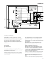
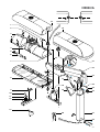
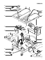
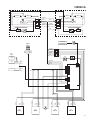
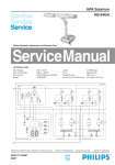
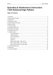
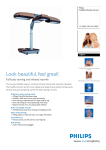
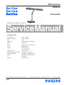
HPA Solarium
HB950/A
Sunmobile
Philips Domestic Appliances and Personal Care
Service Manual
TECHNICAL DATA
Input voltage
Input consumption
Fuse
UVA source
Ballast
Starter
Timer
Cooling
:
:
:
:
:
:
:
:
:
Radiation area
:
Output (min) UVX-36 meter :
Protecting goggles
:
Safety
:
:
Weight
:
230 V - 50 Hz
approx. 1860W
16 A
4x HPA Flexpower 400-600
4x 400 W
integrated soft start system
digital 30 mins
1x fan floor part
2x fan tanning part
190 x 70 cm
3.6 mW/cm2 at 65 cm
2x HB072 - 4822 690 80147
CENELEC insulation class 2
UV type 3
approx. 37 kg
Published by Philips Domestic Appliances and Personal Care
03/05
Printed in the Netherlands
© Copyright reserved
Subject to modification
HB950/A
L
C2
Tr1
C1
C4
C3
C1
Tr2
C2
L
Tr3
N
IR
Tr4
L1
B9
C7
L6
C8
L7
C9
L8
C10
L9
L3
M2
La
3
B5
TCO3
L4
SK3
M3
La
4
B4
M3
SK2
La
2
B6
B2
Tr8
TCO2
L2
B3
Tr7
La
1
B7
B8
Tr6
M4
B1
NC
Tr5
L
C3
CH only
M1
IR
SK1
µC
TCO1
R9
R7
R10
R8
N
N
R5
C11
C12
T1
R6
safety
Re1
M2
N
M1
TECHNICAL INFORMATION
Tanning appliance HB950 is equipped with a universal
power PCB.
This means that the specific characteristics of the appliance
have to be programmed in a microcontroller to determine
the way in which various components are activated.
When the mains plug is inserted into the wall socket, the
display of the remote control will show all functions available
to the user.
These functions are:
time setting
full body tanning
The UV lamps may produce a humming sound just after
start-up. This humming sound will stop as soon as the lamps
burn properly, which is after about 20 seconds. At this point
the light intensity clearly increases.
During the last minute of the session the beeper produces
an intermittent signal to alert the user to the fact that a new
session can be set.
After 750 operating hours, an L will automatically appear
on the display to indicate that the HPA lamps need to be
replaced or the tanning time must be slightly increased.
The clock speed of the µ-controller is derived from the 50 Hz
mains frequency.
This frequency is also used to control the 8 triacs that
determine the switch-in point (soft start) of the cos ϕ
capacitors and the HPA lamps.
The fans are switched via the safety relay.
This relay is part of the (one fault condition) timer circuit.
If the control of the triacs is disturbed due to a fault in the
µ-controller, the UV lamps may not be switched off.
As the µ-controller also generates a pulsating direct voltage
to power the relay, the relay will be de-energised in case of a
fault, thereby interrupting the lamp circuit.
Conversely, the appliance will not start if the switch contacts
of the relay are closed at that moment (sticking contacts).
The remote control is galvanically isolated from the mains,
with power supply and control taking place via a 4-core
cable.
The remote control only functions as input/output terminal.
2-7
HB950/A
HINTS FOR REPAIRS
1. FLOOR PART (item 47)
- Remove the props (item 43) in the grip.
- Remove the covers (item 32 and 44).
The cover on the flex side can only be removed last.
2. REMOTE CONTROL (item 30)
- Detach the cord clamp at the back of the cord holder
and pull the connector loose.
3. WHEEL (item 35)
- Remove the covers (item 32,44).
- Remove the locking plate and the nearest frame screw.
- Push the shaft out of its clamping.
4. STAND LOWER PART (item 27)
- Put the appliance in the lowest operating position
(however, screw (A) must be visible) and tighten the
ornamental screw (item 26)
- Remove the covers from the floor part.
- Detach the 8-core cable so that the cable can easily
slide through the cable duct.
- Remove the shafts (B).
- Remove the 2 bearing bushes (item 28).
- Pull the 8-core cable out of the stand tube to the point
where the clamped joint between the cable bushing
and the protecting sleeve can be unlocked.
- Detach the 8-core cable by loosening the nut of the
bushing a quarter turn.
- Now turn the stand and the radiation units through so
far that the covers (item 14/16) rest on the floor.
- Remove screws (A) and separate the upper and lower
part of the stand.
5. STAND UPPER PART (item 22)
- Loosen the lower part of the stand as described
under .4.
- Hinge the radiation units outwards (the upper part of
the stand rests on the floor).
- Remove the housing parts and detach the wire
connections.
- The covers (item 14/16) can now be separated from
the hinge part.
WHEN A HOUSING AND COVER ARE
ASSEMBLED, SPECIAL ATTENTION SHOULD
BE PAID TO THE POSITIONING OF THE UPPER
BEARING BUSH (see exploded view).
6. HPA LAMP (item 6)
-
Put the appliance in operating position.
Remove the 6 screws from the lamp unit in question.
Remove the cover (item 14 or 16).
Remove 4 reflector clamps.
Remove the reflector and take the lamp from the
holder.
NB: When checking or replacing HPA lamps, pay
attention to the following:
a. HPA lamps only start burning when they have cooled
down sufficiently.
b. Never touch a lamp with your fingers. Clean the lamp
with a cloth moistened with alcohol, if necessary.
c. After assembly the glass filter should be free from
finger prints and dust. Clean the glass filter with a
cloth moistened with alcohol, if necessary.
d. New HPA lamps may show colour differences. This
is not a defect, but a characteristic phenomenon of
lamps of this type. The discolourations disappear
after a short period of use.
e. Always use protecting goggles when looking in the
direction of burning lamps.
7. GAS SPRING (item 17)
- Let the radiation part slowly rise from its transport
position.
- Hinge the radiation units outwards and remove a
decorative cap and spring fix at C.
- Now push the radiation part back into transport
position.
- Use a plastic hammer to tap the pin at C outwards.
NB: CONTINUE TO EXERT PRESSURE ON THE
STAND.
- Hinge the radiation units inwards again and raise the
stand slowly by means of the handle.
- Now turn the stand and the radiation part through so
far that the radiation units rest on the floor.
- The gas spring is now unloaded so that pin (D) can
be easily removed.
- Assemble the new gas spring, the protecting bracket
and cover and press the pin (D) back in place again.
- Lift the radiation part by its handle and check whether
the gas spring with pin (E) is correctly supported in
the fork of the hinged part.
- Press the hinged part against the spring pressure,
moving the radiation part along at the same time until
the whole unit is in horizontal position again.
- Continue to exert pressure and hinge the radiation
units outwards.
- Assemble the pin at C.
- Put the appliance in operating position, and assemble
the remaining clamps.
8. POWER PCB (item 33)
-
Pull the mains plug out of the wall socket.
Remove the cover (item 32, see under .1).
Replace the power PCB and connect all connectors.
Place the cover on the base. The display of the
remote control will now show error code E06 or E05.
- This indicates that the power PCB still needs to
be programmed (code A00) for use in the HB950
according to the input in the table.
The following fault codes have been defined:
E01 - Safety circuit interrupted
This code will appear on the display for 5
seconds, while the beeper produces a loud beep.
Check whether all fans work or whether any UV
filter is missing, broken or damaged.
E02 - Safety relay does nor work according to
specification
Replace the power module (item 33).
E03 / Fault in microprocessor
E04 - Replace the power module (item 33).
E05 / Application code not programmed
E06 - This only occurs in case of a new power
module supplied by Service.
Program the application code, beginning at
line 1, step 3.
3-7
HB950/A
0
1
1
2
Open Service Mode
2
Set Application Code
3
Close Service Mode
E05
E06
3
4
5
6
7
8
9
10
11
C00
Press
+ 1x
C02
2x
+ 1x
+ 1x
A00
1x
+ 1x
+ 1x
A00
0x
+ 1x
C02
1x
C00
2x
00
1x
Item Service code
Description
Item Service code
Description
4222 062 95400
4222 062 95140
4222 062 95490
N.A.
4222 062 95050
orn. screw
stand lower part
bearing bracket (set)
flex holder
cover floorpart L
power module
1
2
3
4
5
4222 062 95270
4222 062 95250
see item 7
4222 062 95260
4822 325 20102
aut. cutout 100 °C
clamp + cap (set)
fan complete
lamp holder
26
27
28
29
30
6
7
8
9
10
4822 134 30032
4222 062 95240
4222 062 95510
4822 214 12662
4822 410 40417
HPA flexpower 400-600
reflector standard
housing tanning part L
14-tabs pcb
switch pin
31
32
33
34
35
4222 062 95090
4222 062 95080
4222 062 94720
see item 9
4822 528 11215
11
12
13
14
15
4822 404 40639
4822 271 30619
4822 690 80147
4222 062 95520
4222 062 95280
switch bracket
micro switch
HB072 protecting goggles
cover tanning part L
hinge parts (set)
36
37
38
39
40
see item 12
4822 265 20234
4222 062 94860
4222 062 94870
4222 062 94850
connecting block mains
4-s connector mains
4-s connector capacitors
9-s connector ballasts
16
17
18
19
20
4222 062 95530
4222 062 95150
4222 062 95020
4222 062 95160
4222 062 95110
cover tanning part R
gas spring
distance indicator
cover gas spring
switch plate
41
42
43
44
45
4222 062 94730
4822 321 11395
4222 062 95070
4222 062 95060
4222 062 94330
fan complete
mains flex
orn. prop (set)
cover floor part R
ballast 400 W /230 V
21
22
23
24
25
4222 062 95540
4222 062 95130
4222 062 95170
4822 530 70444
4222 062 95180
housing tanning part R
stand upper part
orn. strip (set)
spring fix
orn. cap (set)
46
47
48
49
50
4222 062 94740
4222 062 95550
4222 062 95120
4822 528 70519
N.A.
bar grip
housing floor part
clamp
wheel small
51
4222 062 94600
capacitor 50 µF / 250 V
remote control
wheel large
4-7
HB950/A
14
1
16
2
3
4
5
6
15
7
21
C
22
23
E
8
17
18
D
19
A
24
25
9
26
10
11
12
13
20
27
28
B
B
5-7
HB950/A
29
30
31
42
43
32
44
33
38
45
39
34
40
41
46
47
48
49
35
50
36
37
51
6-7
LA 3
LA 2
LA 1
BROWN
N
N
BLUE
BLUE
M3
M2
BROWN
L
3
4
PURPLE
WHITE
LA 4
GREEN
YELLOW
HB950/A
L
YELLOW
GREEN
2
WHITE
PURPLE
1
RED
RED
RED
SK3
SK2
TCO3
TCO2
REMOTE
CONTROL
230V
50Hz
CH
only
PURPLE
GREEN
BROWN
M3/M4
BLUE
M1/M2
N L
YELLOW
WHITE
RED
SK1
C3
TCO1
C1
BLACK
C3
BLUE
C2
BLACK
C4
BLUE
C1
BROWN
BLUE
BLUE
B
B1
WHITE
BROWN
GREEN
YELLOW
C2
1
2
3
4
5
6
7
8
9
L
1
2
C 3
4
N
1
2
M 3
BLACK
B9
B7
RED
PURPLE
BLACK
B8
B6
RED
GREEN
BLACK
B3
B5
RED
YELLOW
BLACK
B2
B4
RED
WHITE
4
M1
L4
400 W
L3
400 W
L2
400 W
L1
400 W
7-7