1
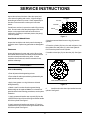
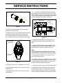
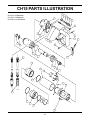
CH15
HYDRAULIC
CHIPPING HAMMER
WARNING
SAFETY, OPERATION AND MAINTENANCE
SERVICE MANUAL
Copyright © 2003, The Stanley Works
SVCE/MAINT USA
35980 11/2003 Ver 1
Stanley Hydraulic Tools
3810 SE Naef Road
Milwaukie OR 97267-5698
503-659-5660
FAX 503-652-1780
www.stanley-hydraulic-tools.com
TABLE OF CONTENTS
Safety Symbols and Precautions ..................................................................... 4, 5
Tool Stickers and Tags ........................................................................................ 6
Hydraulic Hose Requirements ........................................................................... 7
HTMA Requirements ........................................................................................... 8
Operation ............................................................................................................. 9
Equipment Protection and Care ......................................................................... 11
Troubleshooting ................................................................................................ 12
Specifications .................................................................................................... 13
Accessories ....................................................................................................... 13
Service ............................................................................................................... 14
Parts Illustration ................................................................................................. 18
Parts List ............................................................................................................ 19
Warranty ............................................................................................................. 20
SERVICING THE STANLEY CHIPPING HAMMER: This manual contains safety, operation, service and
routine maintenance instructions. Stanley Hydraulic Tools recommends that servicing of hydraulic tools,
other than routine maintenance, must be performed by an authorized and certified dealer. Please read
the following warning.
SERIOUS INJURY OR DEATH COULD RESULT FROM THE IMPROPER REPAIR OR SERVICE OF THIS TOOL.
REPAIRS AND / OR SERVICE TO THIS TOOL MUST ONLY BE
DONE BY AN AUTHORIZED AND CERTIFIED DEALER.
For the nearest authorized and certified dealer, call Stanley Hydraulic Tools at one of the numbers listed
on the back of this manual and ask for a Customer Service Representative.
3
SAFETY SYMBOLS
Safety symbols and signal words, as shown below, are used to emphasize all operator, maintenance and repair
actions which, if not strictly followed, could result in a life-threatening situation, bodily injury or damage to equipment.
This is the safety alert symbol. It is used to alert you to potential personal
injury hazards. Obey all safety messages that follow this symbol to avoid
possible injury or death.
DANGER
This safety alert and signal word indicate an imminently hazardous situation which, if not avoided, will result in death or serious injury.
WARNING
This safety alert and signal word indicate a potentially hazardous situation
which, if not avoided, could result in death or serious injury.
This safety alert and signal word indicate a potentially hazardous situation
which, if not avoided, may result in minor or moderate injury.
This signal word indicates a potentially hazardous situation which, if not
avoided, may result in property damage.
NOTICE
This signal word indicates a situation which, if not avoided, will result in
damage to the equipment.
IMPORTANT
This signal word indicates a situation which, if not avoided, may result in
damage to the equipment.
Always observe safety symbols. They are included for your safety and for the protection of the tool.
LOCAL SAFETY REGULATIONS
Enter any local safety regulations here. Keep these instructions in an area accessible to the operator and maintenance personnel.
4
SAFETY PRECAUTIONS
Tool operators and maintenance personnel must always comply with the safety
precautions given in this manual and on the stickers and tags attached to the
tool and hose.
These safety precautions are given for your safety. Review them carefully before
operating the tool and before performing general maintenance or repairs.
Supervising personnel should develop additional precautions relating to the
specific work area and local safety regulations. If so, place the added precautions in the space provided on page 4.
The CH15 Hydraulic Chipping Hammer will provide safe and dependable service if
operated in accordance with the instructions given in this manual. Read and
understand this manual and any stickers and tags attached to the tool and
hoses before operation. Failure to do so could result in personal injury or
equipment damage.
• Operator must start in a work area without bystanders. The operator must be familiar with all prohibited work
areas such as excessive slopes and dangerous terrain conditions.
• Establish a training program for all operators to ensure safe operation.
• Do not operate the tool unless thoroughly trained or under the supervision of an instructor.
• Always wear safety equipment such as goggles, ear, head protection, and safety shoes at all times when
operating the tool.
• Do not inspect or clean the tool while the hydraulic power source is connected. Accidental engagement of the
tool can cause serious injury.
• Supply hoses must have a minimum working pressure rating of 2500 psi/175 bar.
• Be sure all hose connections are tight.
• The hydraulic circuit control valve must be in the "OFF" position when coupling or uncoupling the tool. Wipe all
couplers clean before connecting. Use only lint-free cloths. Failure to do so may result in damage to the quick
couplers and cause overheating of the hydraulic system.
• Do not operate the tool at oil temperatures above 140°F/60°C. Operation at higher oil temperatures can cause
operator discomfort and may damage the tool.
• Do not operate a damaged, improperly adjusted, or incompletely assembled tool.
• Do not weld, cut with an acetylene torch, or hardface the tool bit.
• To avoid personal injury or equipment damage, all tool repair, maintenance and service must only be performed
by authorized and properly trained personnel.
• Do not exceed the rated limits of the tool or use the tool for applications beyond its design capacity.
• Always keep critical tool markings, such as lables and warning stickers legible.
• Always replace parts with replacement parts recommended by Stanley Hydraulic Tools.
• Check fastener tightness often and before each use daily.
5
TOOL STICKERS & TAGS
Lwa
28323 CE Sticker
Underwater Model Only
11206 Circuit
"C" Sticker
Serial
Number
Stamping
107
58601 Sound Power Level Sticker
Underwater Model Only
11207 Circuit
"D" Sticker
11206 CIRCUIT "C" STICKER (5gpm)
11207 CIRCUIT "D" STICKER (8gpm)
28409 Composite Sticker
Underwater Model Only
Stanley Hydraulic Tools
3810 SE Naef Rd
Milwaukie, Oregon 97267 U.S.A.
Model No.
CH15
26-34 lpm / 7-9 gpm
140 bar / 2000 psi
33513 Name Tag Sticker (CH15521)
36112 Name Tag Sticker (CH15121
& CH1532101)
D A N G E R
1. FAILURE TO USE HYDRAULIC HOSE LABELED AND CERTIFIED
AS NON-CONDUCTIVE WHEN USING HYDRAULIC TOOLS ON
OR NEAR ELECTRICAL LINES MAY RESULT IN DEATH OR SERIOUS INJURY.
BEFORE USING HOSE LABELED AND CERTIFIED AS NON-CONDUCTIVE ON OR NEAR ELECTRIC LINES BE SURE THE HOSE IS
MAINTAINED AS NON-CONDUCTIVE. THE HOSE SHOULD BE
REGULARLY TESTED FOR ELECTRIC CURRENT LEAKAGE IN
ACCORDANCE WITH YOUR SAFETY DEPARTMENT INSTRUCTIONS.
2. A HYDRAULIC LEAK OR BURST MAY CAUSE OIL INJECTION
INTO THE BODY OR CAUSE OTHER SEVERE PERSONAL INJURY.
The safety tag (p/n 15875)
at right is attached to the
tool when shipped from the
factory. Read and understand the safety instructions listed on this tag
before removal. We
suggest you retain this tag
and attach it to the tool
when not in use.
A
DO NOT EXCEED SPECIFIED FLOW AND PRESSURE FOR
THIS TOOL. EXCESS FLOW OR PRESSURE MAY CAUSE A
LEAK OR BURST.
B
DO NOT EXCEED RATED WORKING PRESSURE OF HYDRAU
LIC HOSE USED WITH THIS TOOL. EXCESS PRESSURE MAY
CAUSE A LEAK OR BURST.
C CHECK TOOL HOSE COUPLERS AND CONNECTORS DAILY
FOR LEAKS. DO NOT FEEL FOR LEAKS WITH YOUR HANDS.
CONTACT WITH A LEAK MAY RESULT IN SEVERE PERSONAL
INJURY.
D A N G E R
D DO NOT LIFT OR CARRY TOOL BY THE HOSES. DO NOT
ABUSE HOSE. DO NOT USE KINKED, TORN OR DAMAGED
HOSE.
3. MAKE SURE HYDRAULIC HOSES ARE PROPERLY CONNECTED
TO THE TOOL BEFORE PRESSURING SYSTEM. SYSTEM PRESSURE HOSE MUST ALWAYS BE CONNECTED TO TOOL "IN" PORT.
SYSTEM RETURN HOSE MUST ALWAYS BE CONNECTED TO TOOL
"OUT" PORT. REVERSING CONNECTIONS MAY CAUSE REVERSE
TOOL OPERATION WHICH CAN RESULT IN SEVERE PERSONAL
INJURY.
4. DO NOT CONNECT OPEN-CENTER TOOLS TO CLOSED-CENTER
HYDRAULIC SYSTEMS. THIS MAY RESULT IN LOSS OF OTHER
HYDRAULIC FUNCTIONS POWERED BY THE SAME SYSTEM AND/
OR SEVERE PERSONAL INJURY.
5. BYSTANDERS MAY BE INJURED IN YOUR WORK AREA. KEEP BYSTANDERS CLEAR OF YOUR WORK AREA.
6. WEAR HEARING, EYE, FOOT, HAND AND HEAD PROTECTION.
7. TO AVOID PERSONAL INJURY OR EQUIPMENT DAMAGE, ALL TOOL
REPAIR MAINTENANCE AND SERVICE MUST ONLY BE PERFORMED BY AUTHORIZED AND PROPERLY TRAINED PERSONNEL.
I M P O R TA N T
I M P O R TA N T
READ OPERATION MANUAL AND
SAFETY INSTRUCTIONS FOR THIS
TOOL BEFORE USING IT.
READ OPERATION MANUAL AND
SAFETY INSTRUCTIONS FOR THIS
TOOL BEFORE USING IT.
USE ONLY PARTS AND REPAIR
PROCEDURES APPROVED BY
STANLEY AND DESCRIBED IN THE OPERATION
MANUAL.
USE ONLY PARTS AND REPAIR
PROCEDURES APPROVED BY
STANLEY AND DESCRIBED IN THE OPERATION
MANUAL.
TAG TO BE REMOVED ONLY BY
TOOL OPERATOR.
TAG TO BE REMOVED ONLY BY
TOOL OPERATOR.
SEE OTHER SIDE
SEE OTHER SIDE
SAFETY TAG P/N 15875 (shown smaller then actual size)
6
HYDRAULIC HOSE REQUIREMENTS
HOSE TYPES
Hydraulic hose types authorized for use with Stanley Hydraulic Tools are as follows:
! Certified non-conductive
" Wire-braided (conductive)
$ Fabric-braided (not certified or labeled non-conductive)
Hose ! listed above is the only hose authorized for use near electrical conductors.
Hoses " and $ listed above are conductive and must never be used near electrical conductors.
HOSE SAFETY TAGS
To help ensure your safety, the following DANGER tags are attached to all hose purchased from Stanley Hydraulic
Tools. DO NOT REMOVE THESE TAGS.
If the information on a tag is illegible because of wear or damage, replace the tag immediately. A new tag may be
obtained from your Stanley Distributor.
D A N G E R
D A N G E R
1 FAILURE TO USE HYDRAULIC HOSE LABELED AND CERTIFIED AS NON-CONDUCTIVE WHEN
USING HYDRAULIC TOOLS ON OR NEAR ELECTRIC LINES MAYRESULT IN DEATH OR SERIOUS
INJURY.
FOR PROPER AND SAFE OPERATION MAKE SURE THAT YOU HAVE BEEN PROPERLY TRAINED IN
CORRECT PROCEDURES REQUIRED FOR WORK ON OR AROUND ELECTRIC LINES.
3. DO NOT EXCEED HOSE WORKING PRESSURE OR ABUSE HOSE. IMPROPER USE OR HANDLING
OF HOSE COULD RESULT IN BURST OR OTHER HOSE FAILURE. KEEP HOSE AS FAR AWAY AS
POSSIBLE FROM BODY AND DO NOT PERMIT DIRECT CONTACT DURING USE. CONTACT AT THE
BURST CAN CAUSE BODILY INJECTION AND SEVERE PERSONAL INJURY.
4. HANDLE AND ROUTE HOSE CAREFULLY TO AVOID KINKING, ABRASION, CUTTING, OR CONTACT
WITH HIGH TEMPERATURE SURFACES. DO NOT USE IF KINKED. DO NOT USE HOSE TO PULL OR
LIFT TOOLS, POWER UNITS, ETC.
2. BEFORE USING HYDRAULIC HOSE LABELED AND CERTIFIED AS NON-CONDUCTIVE ON OR
NEAR ELECTRIC LINES. WIPE THE ENTIRE LENGTH OF THE HOSE AND FITTING WITH A CLEAN
DRY ABSORBENT CLOTH TO REMOVE DIRT AND MOSISTURE AND TEST HOSE FOR MAXIMUM
ALLOWABLE CURRENT LEAKAGE IN ACCORDANCE WITH SAFETY DEPARTMENT
INSTRUCTIONS.
5. CHECK ENTIRE HOSE FOR CUTS CRACKS LEAKS ABRASIONS, BULGES, OR DAMAGE TO
COUPLINGS IF ANY OF THESE CONDITIONS EXIST, REPLACE THE HOSE IMMEDIATELY. NEVER
USE TAPE OR ANY DEVICE TO ATTEMPT TO MEND THE HOSE.
6. AFTER EACH USE STORE IN A CLEAN DRY AREA.
SEE OTHER SIDE
SEE OTHER SIDE
SIDE 1
3
D O N O T R E M O V E T H I S TA G
D O N O T R E M O V E T H I S TA G
THE TAG SHOWN BELOW IS ATTACHED TO "CERTIFIED NON-CONDUCTIVE" HOSE
SIDE 2
(shown smaller than actual size)
D A N G E R
D A N G E R
1 DO NOT USE THIS HYDRAULIC HOSE ON OR NEAR ELECTRIC LINES. THIS HOSE IS NOT
LABELED OR CERTIFIED AS NON-CONDUCTIVE. USING THIS HOSE ON OR NEAR ELECTRICAL
LINES MAY RESULT IN DEATH OR SERIOUS INJURY.
5. CHECK ENTIRE HOSE FOR CUTS CRACKS LEAKS ABRASIONS, BULGES, OR DAMAGE TO
COUPLINGS IF ANY OF THESE CONDITIONS EXIST, REPLACE THE HOSE IMMEDIATELY. NEVER
USE TAPE OR ANY DEVICE TO ATTEMPT TO MEND THE HOSE.
2. FOR PROPER AND SAFE OPERATION MAKE SURE THAT YOU HAVE BEEN PROPERLY TRAINED IN
CORRECT PROCEDURES REQUIRED FOR WORK ON OR AROUND ELECTRIC LINES.
6. AFTER EACH USE STORE IN A CLEAN DRY AREA.
3. DO NOT EXCEED HOSE WORKING PRESSURE OR ABUSE HOSE. IMPROPER USE OR HANDLING
OF HOSE COULD RESULT IN BURST OR OTHER HOSE FAILURE. KEEP HOSE AS FAR AWAY AS
POSSIBLE FROM BODY AND DO NOT PERMIT DIRECT CONTACT DURING USE. CONTACT AT
THE BURST CAN CAUSE BODILY INJECTION AND SEVERE PERSONAL INJURY.
4. HANDLE AND ROUTE HOSE CAREFULLY TO AVOID KINKING, CUTTING, OR CONTACT WITH
HIGH TEMPERATURE SURFACES. DO NOT USE IF KINKED. DO NOT USE HOSE TO PULL OR LIFT
TOOLS, POWER UNITS, ETC.
D O N O T R E M O V E T H I S TA G
D O N O T R E M O V E T H I S TA G
THE TAG SHOWN BELOW IS ATTACHED TO "CONDUCTIVE" HOSE.
SEE OTHER SIDE
SEE OTHER SIDE
SIDE 1
SIDE 2
(shown smaller than actual size)
HOSE PRESSURE RATING
The rated working pressure of the hydraulic hose must be equal to or higher than the relief valve setting on the
hydraulic system.
7
HTMA REQUIREMENTS
Tool Category
Hydraulic System
Requirements
20Lpm at 138bar
BHTMA CATEGORY
30Lpm at 138bar
BHTMA CATEGORY
Type I
Type II
40Lpm at 138bar
EHTMA CATEGORY
Type III
Flow rate
Tool Operating Pressure
4-6 gpm
7-9 gpm
10.5-11.6 gpm
11-13 gpm
(15-23 lpm)
(26-34 lpm)
(36-44 lpm)
(42-49 lpm)
(at the power supply outlet)
2000 psi
2000 psi
2000 psi
2000 psi
(138 bar)
(138 bar)
(138 bar)
(138 bar)
System relief valve setting
2100-2250 psi
2100-2250 psi
2100-2250 psi
2100-2250 psi
(at the power supply outlet)
(145-155 bar)
(145-155 bar)
(145-155 bar)
(145-155 bar)
Maximum back pressure
200 psi
200 psi
200 psi
200 psi
(at tool end of the return hose)
(14 bar)
(14 bar)
(14 bar)
(14 bar)
Measured at a max. fluid viscosity of:
(at min. operating temperature)
Temperature
Sufficient heat rejection capacity
to limit max. fluid temperature to:
400 ssu*
400 ssu*
400 ssu*
400 ssu*
(82 centistokes)
(82 centistokes)
(82 centistokes)
(82 centistokes)
140° F (60° C)
140° F (60° C)
140° F (60° C)
140° F (60° C)
3 hp (2.24 kW)
40° F (22° C)
5 hp (3.73 kW)
40° F (22° C)
6 hp (4.47 kW)
40° F (22° C)
7 hp (5.22 kW)
40° F (22° C)
25 microns
18 gpm (68 lpm)
25 microns
25 microns
25 microns
30 gpm (114 lpm) 35 gpm (132 lpm) 40 gpm (151 lpm)
(at max. expected ambient temperature)
Min. cooling capacity
at a temperature difference of
between ambient and fluid temps
NOTE: Do not operate the tool at oil
temperatures above 140° F (60° C). Operation
at higher temperatures can cause operator
discomfort at the tool.
Filter
Min. full-flow filtration
Sized for flow of at least:
(For cold temp. startup and max. dirt-holding
capacity)
Hydraulic fluid
Petroleum based
(premium grade, anti-wear, non-conductive)
Viscosity
(at min. and max. operating temps)
100-400 ssu*
100-400 ssu*
100-400 ssu*
100-400 ssu*
(20-82 centistokes)
(20-82 centistokes)
(20-82 centistokes)
(20-82 centistokes)
NOTE: When choosing hydraulic fluid, the
expected oil temperature extremes that will be
experienced in service determine the
most suitable temperature viscosity
characteristics. Hydraulic fluids with a viscosity
index over 140 will meet the requirements over
a wide range of operating temperatures.
NOTE: These are general hydraulic system requirements. See tool Specification page for tool
specific requirements.
8
OPERATION
2. Try turning the tool bit. If the tool bit does not turn, no
further adjustment is necessary. If the tool bit turns, slide
the chuck adjustor toward the tool bit end of the tool and
then turn it clockwise to close the hex blocks against
the tool bit shank. When the chuck adjustor is properly
set, it should "click" into place and the tool bit should
not turn.
PREOPERATION PROCEDURES
Preparation For Initial Use
The tool, as shipped, has no special unpacking or
assembly requirements prior to usage. Inspection to
assure the tool was not damaged in shipping and does
not contain packing debris is all that is required.
Chuck Adjustor
Check Hydraulic Power Source
1. Using a calibrated flowmeter and pressure gauge,
check that the hydraulic power source develops a flow of
7-9 gpm/26-34 lpm at 1500-2000 psi/105-140 bar for the
CH15100, 8 gpm model.
Chuck Outer
Sleeve
2. Make certain the hydraulic power source is equipped
with a relief valve set to open at 2100-2250 psi/145-155
bar minimum.
3. Check that the hydraulic circuit matches the tool for
open-center (OC) operation.
Installing The Tool Bit
Check Tool
TO INSTALL A ROUND SHANK TOOL BIT
1. Make sure all tool accessories are correctly installed.
Failure to install tool accessories properly can result in
damage to the tool or personal injury.
1. Slide the chuck outer sleeve toward the handle end of
the tool and then insert the tool bit. Release the chuck
outer sleeve.
2. There should be no signs of leaks.
2. If the tool bit can be inserted fully, no other adjustments are necessary. If the tool bit cannot be inserted
fully, slide the chuck adjustor toward the tool bit end of
the tool and then turn it counter clockwise to open the
hex blocks and allow room for the tool bit shank. When
the chuck adjustor is properly set, it should "click" into
place and the tool bit should be fully inserted.
Connect Hoses
3. The tool should be clean, with all fittings and fasteners
tight.
Check Trigger Mechanism
1. Check that the trigger operates smoothly and is free
to travel between the "ON" and "OFF" positions.
Install Tool Bit
1. Wipe all hose couplers with a clean lint-free cloth
before making connections.
The CH16 Chipping Hammer accepts standard .580 inch
hex shank or .680 round shank tool bits.
2. Connect the hoses from the hydraulic power source to
the hose couplers on the tool. It is a good practice to
connect the return hose first and disconnect it last to
minimize or avoid trapped pressure within the tool.
TO INSTALL A HEX SHANK TOOL BIT
1. Slide the chuck outer sleeve toward the handle end of
the tool and then insert the tool bit. Release the chuck
outer sleeve.
3. Observe flow indicators stamped on hose couplers to
be sure that oil will flow in the proper direction. The
female coupler is the inlet coupler.
9
OPERATION
NOTE:
The pressure increase in uncoupled hoses
left in the sun may result in making them
difficult to connect. When possible, connect
the free ends of operating hoses together.
OPERATING PROCEDURES
1. Observe all safety precautions.
2. Move the hydraulic circuit control valve to the "ON"
position.
3. Place the tool bit firmly on the surface to be broken.
4. Squeeze the trigger to start the chipping hammer.
Adequate down pressure is very important.
NOTE:
Partially depressing the trigger allows the
tool to operate at a slow speed, making it
easy to start the tool bit into the surface to
be broken.
NOT FOR UNDERWATER USE
COLD WEATHER OPERATION
f the tool is to be used during cold weather, preheat the
hydraulic fluid at low engine speed. When using the
normally recommended fluids, fluid temperature should
be at or above 50° F/10° C (400 ssu/82 centistokes)
before use.
STORAGE
1. Disconnect the tool from the hydraulic power source.
2. Remove the tool bit and spray the chuck area with
WD-40™ inside and out.
3. Wipe clean and store in a clean, dry place.
10
EQUIPMENT PROTECTION & CARE
In addition to the Safety
Precautions on page 4 & 5
of this manual, observe the
following for equipment
protection and care.
• Make sure all couplers are wiped clean before connection.
• The hydraulic circuit control valve must be in the “OFF” position when coupling or uncoupling
hydraulic tools. Failure to do so may result in damage to the quick couples and cause overheating
of the hydraulic system.
• Always store the tool in a clean dry space, safe from damage or pilferage.
• Make sure the circuit PRESSURE hose (with male quick disconnect) is connected to the “IN” port.
The circuit RETURN hose (with female quick disconnect) is connected to the opposite port. Do not
reverse circuit flow. This can cause damage to internal seals.
• Always replace hoses, couplings and other parts with replacement parts recommended by Stanley
Hydraulic Tools. Supply hoses must have a minimum working pressure rating of 2500 psi/172 bar.
• Do not exceed the rated flow (see Specifications) page 13 in the manual for correct flow rate and
model number. Rapid failure of the internal seals may result.
• Always keep critical tool markings, such as warning stickers and tags legible.
• Do not force a small breaker to do the job of a large breaker.
• Keep tool bit sharp for maximum breaker performance. Make sure that tool bits are not chipped or
rounded on the striking end.
• Never operate a breaker without a tool bit or without holding it against the work surface. This puts
excessive strain on the breaker foot.
• Tool repair should be performed by experienced personnel only.
• Make certain that the recommended relief valves are installed in the pressure side of the system.
• Do not use the tool for applications for which it was not intended.
11
TROUBLESHOOTING
Tool does not run.
Tool does not hit
effectively.
Tool operates slow.
Power unit not functioning.
Check power unit for proper flow
and pressure 7-9gpm/26-34 lpm,
2000 psi/140 bar for 8 gpm
model
Couplers or hoses blocked.
Remove restriction.
Presssure and return line hoses
reversed at ports.
Be sure hoses are connected to
their proper ports.
Mechanical failure of piston or
shuttle valve.
Have inspected and repaired by
authorized dealer.
Power unit not functioning.
Check power unit for proper flow
and pressure 7-9gpm/26-34 lpm,
2000 psi/140 bar for 8 gpm
model
Couplers or hose blocked.
Remove restriction,
Fluid too hot
(above 140° F / 60° C).
Provide cooler to maintain proper
fluid temperature.
Incorrect tool bit
Ensure tool bit meets specifica
tions
Low oil flow from power unit.
Check power source for proper
flow.
High backpressure.
Check hydraulic system for
excessive backpressure and
correct as required.
12
SPECIFICATIONS
Oil Flow Range
CH15521, 5 gpm Model ...................................................................................... 4-6 gpm/15-23 lpm
CH15121, 8 gpm Model ...................................................................................... 7-9 gpm/26-34 lpm
Pressure Range ..................................................................................................... 1000-2000 psi/69-140 Bar
Length ........................................................................................................................................ 17 in./43 cm
Weight ..................................................................................................................................... 16 lb./7.25 kg
Tool Bit ...................................................................................... .580 in. Hex Shank or .680 in. Round Shank
Porting ..................................................................................................................................... -8 SAE O-ring
Couplers ............................................................................. HTMA/EHTMA Flush Face Type Male & Female
Connect Size and Type ......................................................................................... 3/8 in. Male Pipe Adapter
Hose Whips ............................................................................................................................................ Yes
Maximum Back Pressure ........................................................................................................ 250 psi/17 bar
Maximum Fluid Temperature ..................................................................................................... 140° F/60° C
Noise Level ..................................................................................................................................... 106 LWA
Vibration Level .................................................................................................................................. 5.8 m/s2
ACCESSORIES
Description
Part No.
Bushing Tool Bit, .580 Hex ................................................................................................................... 02277
Flat Chisel Bit, 1 in. x 18 in., .580 Hex ................................................................................................. 02278
Bull Point Bit, 1 in. x 18 in., .580 Hex .................................................................................................. 02279
Chisel Bit, 1 in. x 9 in., .580 Hex .......................................................................................................... 03690
Chisel Bit, 2 in. x 5 in., .580 Hex .......................................................................................................... 03963
Chisel Bit, 1 in. x 14 in., .680 Round .................................................................................................... 02339
Moil Point, 18 in., .680 Round .............................................................................................................. 04401
Moil Point, 14 in., .680 Round .............................................................................................................. 04901
Chisel Bit, 3 in. x 14 in., .680 Round .................................................................................................... 02330
Chisel Bit, 3 in. x 18 in., .680 Round .................................................................................................... 04402
Bruning Flush Face Coupler Set, 3/8 NPT ............................................................................................ 03971
Bruning Flush Face Coupler Set, 1/2 NPT ............................................................................................ 03974
Aeroquip Flush Face Coupler Set, 3/8 NPT .......................................................................................... 24069
Aeroquip Flush Face Coupler Set, 1/2 NPT .......................................................................................... 24070
Hose, 50 ft. x 1/2 in. ID, wire braid, dual, with couplers ........................................................................ 31848
Hose, 25 ft. x 1/2 in. ID, wire braid, dual, with couplers ........................................................................ 31972
Seal Kit ................................................................................................................................................ 35979
13
SERVICE INSTRUCTIONS
Follow the procedures contained in the HYDRAULIC
SYSTEM REQUIREMENTS section of this manual to
ensure peak performance from the tool. Never disassemble the tool unless proper troubleshooting procedures have isolated the problem to an internal part. Then,
only disassemble it to the extent necessary to replace
the defective part.
KEEP CONTAMINANTS SUCH AS DIRT AND GRIT AWAY
FROM INTERNAL PARTS AT ALL TIMES.
Always determine and correct the cause of the problem
prior to reassembly. Further wear and tool failure can
result if the original cause is not corrected.
PRIOR TO DISASSEMBLY
7. Remove the pigtail hose assemblies.
Note:
The tool is full of fluid and will drip from the ports
when the hoses are removed.
8. Unscrew and remove the 4 capscrews (23) and set
the handle (17) aside being careful to prevent the trigger
pin (24), valve sleeve (14), and valve spool (12) from
falling out. Remove these items from the handle or body
(9) and set them aside.
9. Unscrew and remove the 4 capscrews (16). Remove
the body from the cylinder. Tapping on the body with a
soft faced mallet may be required to assist in the
removal. Be careful to prevent the tube (32) from falling
out as it may stay in the body as the body is removed.
10. Remove the tube and the shuttle valve (34) and set
them aside.
• Clean the exterior of the tool.
• Obtain a seal kit to replace all seals exposed during
disassembly. Note the orientation of seals before
removing them. Install new seals in the same position as
original seals.
DISASSEMBLY
11. Slide the piston (31) out of the cylinder and set it
aside.
12. The trigger (20) may be removed from the handle by
driving out the 2 spirol pins (22).
13. Remove all seals and discard them.
INSPECTION OF PARTS
1. Slide the outer chuck sleeve (43) toward the handle
and remove the retaining ring (42). Slide off the outer
chuck sleeve being careful to catch the 3 steel balls
(37). Remove the spring (44), and retaining ring (46).
Piston and Cylinder
2. Slide the chuck adjuster off of the shank (36) being
careful to not let the hex blocks (38) and springs (35) fall
out of the shank. Slide the hex blocks and springs out of
the shank.
Inspect the surface of the bore of the cylinder and the
surface of the piston for wear, galling, and cracks. A
light scuffing or burnishing of surfaces is normal. Check
especially for freedom of movement of the parts and that
the piston does not stick or bind as it is moved in the
cylinder. Coat the parts with hydraulic oil for this test.
3. Slide the foam grip (39) off of the shank.
4. Unscrew and remove the capscrews (45).
5. Pull the shank away from the cylinder (29). A soft
faced mallet may be required to assist in the shank
removal by tapping on the shank.
If small burrs are found, remove them with 220 grit emery
cloth.
If galling or cracks are present, the part(s) must be
replaced.
Valve Sleeve and Valve Spool
6. Secure the tool in a bench vise, with the “IN” and
“OUT” ports up, clamping on the cylinder. Soft vise jaws
are necessary.
14
SERVICE INSTRUCTIONS
Inspect the surface of the bore of the valve spool and
valve sleeve for galling and cracks. A light scuffing or
burnishing of surfaces is normal. Check espescially for
freedom of movement of the valve spool in the valve
sleeve.
CYLINDER
CUP SEAL
SCRAPER
If small burrs are found, remove them with 220 grit emery
cloth. Do not break or buff the sharp edges of the valve
sleeve or valve spool as this will cause the valve to
malfunction. If galling or cracks are present, the part(s)
must be replaced.
PISTON
Figure 1.
Hex Block and Chuck Parts
3. Apply grease and install a new o-ring (30) onto the
cylinder.
Inspect the hex blocks and chuck parts for damage or
excessive wear. Replace any parts that are damaged or
worn.
4. Place the cylinder (29) into a vice with soft jaws. Coat
the cylinder bore and piston (31) with clean hydraulic
fluid. Insert the piston into the cylinder.
Fasteners
5. Install the dowel pin (33) into the tube (32). See figure
2.
Inspect all fasteners for wear and cracks. When clean
and coated with anti-sieze, the fasteners should thread
into their related parts without any effort. If some
resistance is encountered, check the threads for dirt
particles or damage.
DOWEL PIN
LOCATION
ASSEMBLY
Prior to Assembly
• Clean all parts with a degreasing solvent.
• Ensure that all seals exposed during disassembly are
replaced with new parts.
TUBE VIEWED FROM BOTTOM
• Apply clean grease or o-ring lubricant to all seals
during assembly.
Figure 2.
• Obtain a seal kit so that all seals exposed during
disassembly can be replaced. Note: For orientation of
parts identified in the following procedures, see the parts
illustration.
6.
Install the tube with dowel pin installed onto the
cylinder. See figure 3.
1. Apply grease and install a new cup seal (28) into the
cylinder with the lips of the seal facing toward the handle
end of the cylinder. See figure 1.
2. Apply grease and install a new scraper (27) into the
cylinder with the lips of the seal facing toward the handle
end of the cylinder. See figure 1.
15
SERVICE INSTRUCTIONS
12.
Lubricate the valve spool and valve sleeve with
clean hydraulic fluid. Insert the valve spool into the valve
sleeve. Install the insert (11) onto the valve sleeve. Install
a new o-ring (10) around the outer diameter of the insert.
Insert this assembly into the body. See figure 5.
VALVE SLEEVE (14)
O-RING (10)
HANDLE (17)
O-RING (15)
O-RING (13)
Figure 3
7. Lubricate with clean hydraulic fluid and install the
shuttle valve (34) into the tube.
INSERT (11)
8. Install the body (9) over the tube and shuttle valve onto
the cylinder. Ensure the suttle valve and roll pin are
correctly aligned with holes in the body. See figure 4.
Use a soft faced mallet to tap the body onto the cylinder.
VALVE SPOOL (12)
Figure 5.
13. Apply grease and install 4 o-rings (15) into the
grooves surrounding the capscrew (16) holes 1n the
body.
BODY VIEWED
FROM BOTTOM
14. Apply a light coat of grease to the trigger pin (24)
and install it into the handle. Install the handle onto the
body using 4 capscrews (23). Tighten to 25 ft. lbs.
NOTE:
If the trigger was disassembled from the handle,
reinstall it before installing the handle to the body.
DOWEL PIN
LOCATION
15. Apply grease and install a new o-ring (6) into the
groove on the control shaft.
Figure 4.
16. Install the shank (36) to the cylinder. Apply Loctite™
and install 4 capscrews (45).Tighten to 15 ft. lb. There is
no special alignment of the shank to the cylinder. Use
the parts drawing as a guide for alignment.
9. Install the 4 capscrews (16) and tighten to 25 ft. lbs.
17. Install the foam grip (39) over the shank and cylinder.
10. Apply grease and install a new o-ring (15) onto the
valve sleeve (14).
18. Apply Kopr-Kote™ to the springs (35) and insert
each of them into a hole in one of the hex block (38)
halves. Install the other hex block halve over the springs
and then install the assembly into the slot in the shank
11. Apply grease and install a new o-ring (13) onto the
valve spool (12).
16
SERVICE INSTRUCTIONS
and hold it in place with one hand. Obtain the chuck
adjustor (40) and turn it so that the end containing 4
channels is facing toward the handle. Slide the chuck
adjustor onto the shank and over the slot containing the
hex blocks and springs.
19. Apply grease and install the 3 steel balls (37). Install
the retaining ring (46), the spring (44), outer chuck (43)
and retaining ring (42).
20. Install the hose assemblies (47) making sure the
female coupler is installed to the "IN" port and the male
coupler is installed to the "OUT" port.
TESTING FOR OPERATION AND
PERFORMANCE
1. Install a tool bit.
2. Connect the tool to a hydraulic power source.
3. Operate the tool with the bit pressed against a hard
surface. The tool should not stall.
4. Turn the tool "ON" and "OFF" several times to ensure
the valve is operating correctly.
5. Test the speed control by moving the speed adjuster
lever back and forth.
STORAGE
1. Disconnect the tool from the hydraulic power source.
2. Remove the tool bit and spray the chuck area with
WD-40™ inside and out.
3. Wipe clean and store in a clean, dry place.
17
CH15 PARTS ILLUSTRATION
10
11
CH15121, 8 GPM Model
CH15521, 5 GPM Model
CH1532101, 8 GPM Model
12
13
9
14
15
16
8
26
25
5
17
15
24
23
27
22
28
29
30
31
20
47
40
32
33
34
39
35
38
46
37
36
OIL IN
48
42
43
44
45
18
18
CH15 PARTS LIST
ITEM
P/N
1
2
3
4
5
6
7
8
9
10
11
12
13
14
15
16
17
18
19
20
21
22
23
24
25
----------------07492
28323
11211
28409
35544
00016
33268
31583
31650
31597
01211
24871
35533
62197
----62198
00878
31602
13815
31582
33513
36112
11206
11207
31607
31606
36111
35961
07572
33520
31590
33521
35547
35546
31592
33293
31585
38596
12100
31586
33294
31587
----33292
31588
33291
35976
38597
01412
03971
26
27
28
29
30
31
32
33
34
35
36
37
38
39
40
41
42
43
44
45
46
47
48
QTY
----1
1
1
1
1
1
1
1
1
1
5
4
1
1
-1
1
1
4
1
1
1
1
1
1
1
1
1
1
1
1
1
1
1
1
4
1
1
3
2
1
1
-1
1
1
4
1
2
1
DESCRIPTION
MODEL DESIGNATIONS
NO ITEM
NO ITEM
NO ITEM
NO ITEM
SPIROL PIN
CE STICKER
SOUND PWR LEVEL STICKER
COMPOSITE STICKER
BODY
O-RING 2-015 R16
INSERT
VALVE SPOOL
O-RING, .176x.040, 5 -193
VALVE SLEEVE
O-RING 2-016 R16
CAPSCREW 5/16-18UNC x 3
HANDLE
TRIGGER ROD
NO ITEM
TRIGGER
DOWEL PIN, 3/16 X 1/2 SS
SPIROL PIN 5/32 x 1.2
CAPSCREW 5/16-18UNC x 1
TRIGGER PIN
NAME TAG, CH15521 MODEL
NAME TAG, CH15121 MODEL
CIRCUIT "C" STICKER, CH15521MODEL
CIRCUIT “D” STICKER, CH15121MODEL
SCRAPER
CUP SEAL
CYLINDER, CH15121 MODEL
CYLINDER, CH15521 MODEL
O-RING 2-135 R16
PISTON, CH15121 MODEL
PISTON, CH15521 MODEL
TUBE, CH15121 MODEL
TUBE, CH15521 MODEL
DOWEL PIN, 5/32 X 1.500
SHUTTLE VALVE
SPRING
SHANK
SHANK - UNDERWATER MODEL ONLY
STEEL BALL 3/8 DIA. G
HEX BLOCK
FOAM GRIP
CHUCK ADJUSTOR
NO ITEM
RETAINING RING
CHUCK OUTER SLEEVE
SPRING
CAPSCREW 1/4X1.500
RETAINING RING - U/W MODEL ONLY
PIGTAIL HOSE ASSY 12
FLUSH FACE COUPLER SET
19
CH15521
CH15121
SEAL KIT
5 gpm Model
8 gpm Model
35979
WARRANTY
Stanley Hydraulic Tools (hereinafter called “Stanley”), subject to the exceptions contained below, warrants new hydraulic tools for a period
of one year from the date of sale to the first retail purchaser, or for a period of 2 years from the shipping date from Stanley, whichever
period expires first, to be free of defects in material and/or workmanship at the time of delivery, and will, at its option, repair or replace any
tool or part of a tool, or new part, which is found upon examination by a Stanley authorized service outlet or by Stanley’s factory in
Milwaukie, Oregon to be DEFECTIVE IN MATERIAL AND/OR WORKMANSHIP.
EXCEPTIONS FROM WARRANTY
FREIGHT COSTS: Freight costs to return parts to Stanley, if requested by Stanley for the purpose of evaluating a warranty claim for
warranty credit, are covered under this policy if the claimed part or parts are approved for warranty credit. Freight costs for any part or
parts which are not approved for warranty credit will be the responsibility of the individual.
SEALS & DIAPHRAGMS: Seals and diaphragms installed in new tools are warranted to be free of defects in material and/or workmanship
for a period of 6 months after the date of first usage, or for a period of 2 years from the shipping date from Stanley, whichever period
expires first.
CUTTING ACCESSORIES: Cutting accessories such as breaker tool bits are warranted to be free of defects in material and or workmanship at the time of delivery only.
ITEMS PRODUCED BY OTHER MANUFACTURERS: Components which are not manufactured by Stanley and are warranted by their
respective manufacturers.
a. Costs incurred to remove a Stanley manufactured component in order to service an item manufactured by other
manufacturers.
ALTERATIONS & MODIFICATIONS: Alterations or modifications to any tool or part. All obligations under this warranty shall be terminated
if the new tool or part is altered or modified in any way.
NORMAL WEAR: any failure or performance deficiency attributable to normal wear and tear such as tool bushings, retaining pins, wear
plates, bumpers, retaining rings and plugs, rubber bushings, recoil springs, etc.
INCIDENTAL/CONSEQUENTIAL DAMAGES: To the fullest extent permitted by applicable law, in no event will STANLEY be liable for any
incidental, consequential or special damages and/or expenses.
FREIGHT DAMAGE: Damage caused by improper storage or freight handling.
LOSS TIME: Loss of operating time to the user while the tool(s) is out of service.
IMPROPER OPERATION: Any failure or performance deficiency attributable to a failure to follow the guidelines and/or procedures as
outlined in the tool’s operation and maintenance manual.
MAINTENANCE: Any failure or performance deficiency attributable to not maintaining the tool(s) in good operating condition as outlined in
the Operation and Maintenance Manual.
HYDRAULIC PRESSURE & FLOW: Any failure or performance deficiency attributable to excess hydraulic pressure, excess hydraulic
back-pressure, or excess hydraulic flow.
REPAIRS OR ALTERATIONS: Any failure or performance deficiency attributable to repairs by anyone which in Stanley’s sole judgement
caused or contributed to the failure or deficiency.
MIS-APPLICATION: Any failure or performance deficiency attributable to mis-application. “Mis-application” is defined as usage of
products for which they were not originally intended or usage of products in such a matter which exposes them to abuse or accident,
without first obtaining the written consent of Stanley.
WARRANTY REGISTRATION: STANLEY ASSUMES NO LIABILITY FOR WARRANTY CLAIMS SUBMITTED FOR WHICH NO TOOL REGISTRATION IS ON RECORD. In the event a warranty claim is submitted and no tool registration is on record, no warranty credit will be issued
without first receiving documentation which proves the sale of the tool or the tools’ first date of usage. The term “DOCUMENTATION” as
used in this paragraph is defined as a bill of sale, or letter of intent from the first retail customer. A WARRANTY REGISTRATION FORM
THAT IS NOT ALSO ON RECORD WITH STANLEY WILL NOT BE ACCEPTED AS “DOCUMENTATION”.
NO ADDITIONAL WARRANTIES OR REPRESENTATIONS
This limited warranty and the obligation of Stanley thereunder is in lieu of all other warranties, expressed or implied including merchantability or fitness for a particular purpose except for that provided herein. There is no other warranty. This warranty gives the purchaser
specific legal rights and other rights may be available which might vary depending upon applicable law.
20
Stanley Hydraulic Tools
3810 SE Naef Road
Milwaukie OR 97267-5698
503-659-5660
FAX 503-652-1780
www.stanley-hydraulic-tools.com