1
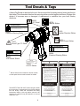
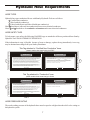
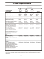
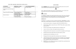
®
Service Manual
ID07
Impact Drill/
Wrench
DANGER
SERIOUS INJURY OR DEATH COULD RESULT
FROM THE IMPROPER REPAIR OR SERVICE OF
THIS TOOL.
Copyright c 2003 The Stanley Works
USA & CE Version
60788 7/2003 Ver. 1
REPAIRS AND/OR SERVICE TO THIS TOOL
MUST ONLY BE DONE BY AN AUTHORIZED AND
CERTIFIED DEALER.
Table of Contents
ID07
Impact Drill/
Wrench
SERVICING THE
ID07 IMPACT DRILL/WRENCH:
This manual contains Safety,
Operation, and Troubleshooting
information. Stanley Hydraulic Tools
recommends that servicing of
hydraulic tools, other than routine
maintenance, must be performed by
an authorized and certified dealer.
Please read the DANGER warning
on the cover and the SAFETY
warning below.
Copyright c 2003 The Stanley Works
All rights reserved.
Certificate of Conformity
3
Specifications
4
General Safety Instructions
5
Tool Decals and Tags
6
Hydraulic Hose Requirements
7
HTMA Requirements
8
Operating Instructions
9
Service Instructions
12
Troubleshooting
15
Parts Illustration
16
Parts List
17
Accessories
19
Warranty
20
SAFETY FIRST
Under copyright law, this document may
not be copied in whole or in part without
the prior written consent of The Stanley
Works. This exception does not permit
copies to be made for others, whether or
not sold. Under the law, copying includes
translating into another language, format
or medium. This copyright notice must
appear on any permitted copies.
It is the responsibility of the operator and
service technician to read rules and
instructions for safe and proper operation
and maintenance.
A cautious worker using common sense is
the greatest safety device.
2
Certificate of Conformity
CERTIFICATE OF CONFORMITY
ÜBEREINSTIMMUNGS-ZERTIFIKAT
CERTIFICAT DE CONFORMITE CEE
CERTIFICADO DE CONFORMIDAD
CERTIFICATO DI CONFORMITA
Hydraulic Tools
I, the undersigned:
Ich, der Unterzeichnende:
Je soussigné:
El abajo firmante:
lo sottoscritto:
Burrows, James
Surname and First names/Familiennname und Vemamen/Nom et prénoms/Nombre y apellido/Cognome e nome
hereby certify that the construction plant or equipment specified hereunder:
bestätigt hiermit, daß die Konstruktion und Ausrüstung wie folgt spezifiziert ist:
atteste que le brise-béton:
por el presente certifico que la fabrica o el equipo especificado a continuacion:
certifico che l’impianto o l’attrezzatura sotto specificata:
1. Category: Impact Drills
Kategorie:
Catégorie:
Categoria:
Categoria:
2. Make/Ausführung/Marque/Marca/Fabbricazion: Stanley
3. Type/Typ/Type/Tipo/Tipo: ID0781001, ID0782001
4. Type serial number of equipment:
Typ und Serien - Nr. der Ausrüstung:
Numéro dans la série du type de matériel:
Numero de serie tipo del equipo:
Matricola dell´attrezzatura:
ALL
5. Year of manufacture/Baujahr/année de fabrication/Año de fabricacion/Anno di fabbricazione: 2003
has been manufactured in conformity with - EEC Type examination as shown.
wurde hergestellt in Übereinstimmung mit - EEC Typ-Prüfung nach.
est fabriqué conformément - au(x) type(s) examiné(s) comme indiqué dans le tableau di-après.
ha sido fabricado de acuerdo con - tipo examen EEC como dice.
è stata costruita in conformitá con - le norme CEE come illustrato.
Directive
Richtlinie
Directives particulières
Directriz
Direttiva
No.
Nr
Numéro
No
n.
Date
Datum
Date
Fecha
Data
Approved body
Prüfung durch
Organisme agréé
Aprobado
Collaudato
Date of expiry
Ablauf datum
Date d´expiration
Fecha de caducidad
Data di scadenza
EN
EN ISO
EN
792-6
3744
28662-7
1994
1995
1997
Self
Self
Self
NA
NA
NA
6.
Special Provisions: None
Spezielle Bestimmungen:
Dispositions particulières:
Provisiones especiales:
Misure special:
Sound Level:
108 dBA
Vibration Level: 2.0 m/s2
Done at/Ort/Fait à/Dado en/Fatto a Stanley Hydraulic Tools, Milwaukie, Oregon USA
Date/Datum/le/Fecha/Data 6/16/03
Signature/Unterschrift/Signature/Firma/Firma
Position/Position/Fonction/Puesto/Posizione Engineering Manager
3
Specifications
Drive Size__________1/2 in. square or 7/16 in. hex
Pressure Range___________ 2000 psi / 140 bar
Flow Range_____________4-12 gpm / 15-45 lpm
Optimum Flow____________4-9 gpm / 15-34 lpm
Porting_______________________-8 SAE O-ring
Connect Size & Type___ 3/8 in. NPT Pipe Fitting
Weight (less couplers)__________7.2 lbs. / 3.3 kg
Overall Length________________ 9 in. / 22.9 cm
Width______________________ 4.5 in. / 11.4 cm
Height_____________________ 10.5 in. / 26.7 cm
Motor____________________________ Integral
Outport Torque_____________500 ft lbs / 675 Nm
Max. Fluid Temp._____________ 140° F / 60° C
HTMA Class I ____________4-6 gpm @ 2000 psi
EHTMA Category______20 lpm @ 138 bar
HTMA Class II___________7-9 gpm @ 2000 psi
30Lpm at 138bar
BHTMA CATEGORY
EHTMA Category_____30 lpm @ 138 bar
Sound Power Level_______________104.5 dBA
Vibration Level_____________________6.4 m / s2
4
General Safety Instructions
Always observe safety symbols. They are included for your safety and the protection of the tool.
WARNING
DANGER
This safety symbol may appear on
the tool. It is used to alert the
operator of an action that could
place him/her or others in a life
threatening situation.
This safety symbol appears in these
instructions to identify an action
that could cause bodily injury to the
operator or other personnel.
CAUTION
This safety symbol appears in these
instructions to identify an action or
condition that could result in
damage to the tool or other
equipment.
This tool will provide safe and dependable service if operated in accordance with the instructions
given in this manual. Read and understand this manual and any stickers and tags attached to the
tool and hoses before operation. Failure to do so could result in personal injury or equipment
damage.
h
Operator must start in a work area without bystanders. The operator must be familiar with all prohibited
work areas such as excessive slopes and dangerous terrain conditions.
h
Establish a training program for all operators to ensure safe operations.
h
Do not operate the tool unless thoroughly trained or under the supervision of an instructor.
h
Always wear safety equipment such as goggles, head protection, and safety shoes at all times when
operating the tool.
h
Do not inspect or clean the tool while the hydraulic power source is connected. Accidental engagement of
the tool can cause serious injury.
h
Do not operate this tool without first reading the Operating Instructions.
h
Do not install or remove this tool while the hydraulic power source is connected. Accidental engagement
of the tool can cause serious injury.
h
Never operate the tool if you cannot be sure that underground utilities are not present. Underground
electrical utilities present an electrocution hazard. Underground gas utilities present an explosion hazard.
Other underground utilities may present other hazards.
h
Do not operate in a potentially explosive atmosphere.
h Do not wear loose fitting clothing when operating the tool. Loose fitting clothing can get entangled with
the tool and cause serious injury.
h
Supply hoses must have a minimum working pressure rating of 2500 psi/175 bar.
h
Be sure all hose connections are tight.
h
The hydraulic circuit control valve must be in the “OFF” position when coupling or uncoupling the tool.
Wipe all couplers clean before connecting. Failure to do so may result in damage to the quick couplers
and cause overheating. Use only lint-free cloths.
h
Do not operate the tool at oil temperatures above 140° F/60° C. Operation at higher oil temperatures can
cause operator discomfort and may cause damage to the tool.
h
Do not operate a damaged, improperly adjusted, or incompletely assembled tool.
h
To avoid personal injury or equipment damage, all tool repair, maintenance and service must only be
performed by authorized and properly trained personnel.
h
Do not exceed the rated limits of the tool or use the tool for applications beyond its design capacity.
h
Always keep critical tool markings, such as labels and warning stickers legible.
h
Always replace parts with replacement parts recommended by Stanley Hydraulic Tools.
5
Tool Decals & Tags
A Name Tag Sticker is attached to the tool. Never exceed the flow and pressure levels specified on
this sticker.The information listed on the name tag sticker must be legible at all times. Replace this
sticker if it becomes worn or damaged. A replacement is available from your local Stanley
distributor.
28323
28788
“CE” Decal
Manual Sticker
WARNING
Correctly connect hoses to tool ports. Do not exceed specified flow or
pressure. Improper handling, use or maintenance can cause a leak or
burst that can result in oil injection to the body. Failure to observe these
precautions may result in serious personal injury.
29149
Rotation Direction Sticker
58862
Pressure Warning Sticker
LWA
30Lpm at 138bar
BHTMA CATEGORY
108 29530
Sound Power Sticker
11207
Circuit Type “D” Decal
WARNING
Read owners manual and ensure that youPhave been
properly trained to work on orParound electric lines. Failure to
use hydraulicPhose labeled and certified as
non-conductivePmay result in death or serious personal injury.
Stanley Hydraulic Tools
R
Model No.
Id07
3810 SE Naef Rd
Milwaukie, Oregon 97267 U.S.A.
58864
Electrical Warning Sticker
15-46 lpm/4-12 gpm
140 bar/2000 psi
60806
ID07 Model Sticker
OC/CC
FOR USE ON OPEN CENTER AND CLOSED
CENTER HYDRAULIC SYSTEMS, "SET FOR
PROPER SYSTEM BEFORE USE"
11354
OC/CC Sticker
DANGER
1. FAILURE TO USE HYDRAULIC HOSE LABELED AND
CERTI-FIED AS NON-CONDUCTIVE WHEN USING
HYDRAULIC TOOLS ON OR NEAR ELECTRICAL LINES
MAY RESULT IN DEATH OR SERIOUS INJURY.
BEFORE USING HOSE LABELED AND CERTIFIED AS
NON- CONDUCTIVE ON OR NEAR ELECTRIC LINES.
BE SURE THE HOSE IS MAINTAINED AS NON- CONDUCT IVE . THE
HOSE SHOULD BE REGULARLY TESTED FOR ELECTRIC CURRENT
LEAKAGE IN ACCORDANCE WITH YOUR SAFETY DEPARTMENT
INSTRUCTIONS.
2. A HYDRAULIC LEAK OR BURST MAY CAUSE OIL
INJECTION INTO THE BODY OR CAUSE OTHER SEVERE PERSONAL
INJURY.
A.DO NOT EXCEED SPECIFIED FLOW AND
PRESSURE FOR THIS TOOL. EXCESS FLOW OR
PRESSURE MAY CAUSE A LEAK OR BURST.
B. DO NOT EXCEED RATED WORKING PRESSURE
OF HYDRAULIC HOSE USED WITH THIS TOOL.
EXCESS PRESSURE MAY CAUSE A LEAK OR
BURST.
C. C H E C K T O O L , H O S E , C O U P L E R S &
C O N N E C T O R S
D A I L Y
F O R
LEAKS. DO NOT FEEL FOR LEAKS WITH
YOUR HANDS. CONTACT WITH A LEAK MAY
RESULT IN SEVERE PERSONAL INJURY.
* Not all stickers are furnished on all tool models.
Consult parts list and model number for details.
The SAFETY TAG, P/N 15875, shown at right, smaller
than actual size, is attached to the tool when shipped
from the factory. Read and understand the safety
instructions listed on this tag before removal. We
suggest you retain this tag and attach it to the tool
when not in use.
6
DANGER
D. DO NOT LIFT OR CARRY TOOL BY THE HOSES. DO NOT ABUSE
HOSE. DO NOT USE KINKED, TORN OR DAMAGED HOSES.
3. MAKE SURE HYDRAULIC HOSES ARE PROPERLY
CONN-ECTED TO THE TOOL BEFORE PRESSURIZING
SYSTEM. SYSTEM PRESSURE HOSE MUST ALWAYS
BE CONNECTED TO TOOL “IN” PORT. SYSTEM
RETURN HOSE MUST ALWAYS BE CONNECTED AT
TOOL “OUT” PORT. REVERSING CONNECTIONS MAY
CAUSE REVERSE TOOL OPERATION WHICH CAN
CAUSE SEVERE PERSONAL INJURY.
4. DO NOT CONNECT CLOSED-CENTER TOOLS TO
OPEN-CENTER HYDRAULIC SYSTEMS. THIS MAY
CAUSE EXTREME SYSTEM HEAT AND/OR SEVERE
PERSONAL INJURY.
DO NOT CONNECT OPEN-CENTER TOOLS TO CLO SE D- CE NT ER
HYDRAULIC SYSTEMS. THIS MAY RESULT IN LOSS OF OTHER
HYDRAULIC FUNCTIONS POWERED BY THE SAME SYSTEM AND/OR
SEVERE PERSONAL INJURY.
5. BYSTANDERS MAY BE INJURED IN YOUR WORK
AREA. KEEP BYSTANDERS CLEAR OF YOUR WORK
AREA.
6. WEAR HEARING, EYE, FOOT, HAND AND HEAD PROTECTION.
7. TO AVOID PERSONAL INJURY OR EQUIPMENT DAMAGE, ALL TOOL
REPAIR, MAINTENANCE AND
SERVICE MUST BE
PERFORMED BY AUTHORIZED
AN D PR OP ER LY
TRAINED PERSONNEL.
IMPORTANT
IMPORTANT
READ OPERATION MANUAL AND
SAFETY INSTRUCTIONS FOR THIS
TOOL BEFORE USING IT.
READ OPERATION MANUAL AND
SAFETY INSTRUCTIONS FOR THIS
TOOL BEFORE USING IT.
USE ONLY PARTS AND REPAIR
PROCEDURES APPROVED BY
STANLEY AND DESCRIBED IN THE
OPERATION MANUAL.
USE ONLY PARTS AND REPAIR
PROCEDURES APPROVED BY
STANLEY AND DESCRIBED IN THE
OPERATION MANUAL.
TAG TO BE REMOVED ONLY BY TOOL
OPERATOR.
(517)
SEE OTHER SIDE
15875
TAG TO BE REMOVED ONLY BY TOOL
OPERATOR.
(517)
SEE OTHER SIDE
15875
Hydraulic Hose Requirements
HOSE TYPES
Hydraulic hose types authorized for use with Stanley Hydraulic Tools are as follows:
Certified non-conductive
Wire-braided (conductive)
Fabric-braided (not certified or labeled non-conductive)
Hose listed above is the only hose authorized for use near electrical conductors.
Hoses and listed above are conductive and must never be near electrical conductors.
HOSE SAFETY TAGS
To help ensure your safety, the following DANGER tags are attached to all hoses purchased from Stanley
Hydraulic Tools. DO NOT REMOVE THESE TAGS.
If the information in a tag is illegible because of wear or damage, replace the tag immediately. A new tag
may be obtained at no charge from your Stanley Distributor.
This Tag attached to “Certified Non-Conductive” hose.
DANGER
DANGER
1. FAILURE TO USE HYDRAULIC HOSE LABELED AND CERTIFIED AS NON-CONDUCTIVE WHEN USING
HYDRAULIC TOOLS ON OR NEAR ELECTRIC LINES MAY RESULT IN DEATH OR SERIOUS INJURY.
FOR PROPER AND SAFE OPERATION, MAKE SURE THAT YOU HAVE BEEN PROPERLY TRAINED IN
CORRECT PROCEDURES REQUIRED FOR WORK ON OR AROUND ELECTRIC LINES.
4. HANDLE AND ROUTE HOSE CAREFULLY TO AVOID KINKING, ABRASION, CUTTING OR CONTACT
WITH HIGH TEMPERATURE SURFACES. DO NOT USE IF KINKED. DO NOT USE HOSE TO PULL OR
LIFT TOOLS, POWER UNITS, ETC.
5. CHECK ENTIRE HOSE FOR CUTS, CRACKS, LEAKS, ABRASIONS, BULGES OR DAMAGE TO
COUPLINGS. IF ANY OF THESE CONDITIONS EXIST, REPLACE THE HOSE IMMEDIATELY.
NEVER USE TAPE OR ANY DEVICE TO ATTEMPT TO MEND THE HOSE.
2. BEFORE USING HYDRAULIC HOSE LABELED AND CERTIFIED AS NON-CONDUCTIVE ON OR NEAR
ELECTRIC LINES, WIPE THE ENTIRE LENGTH OF THE HOSE AND FITTINGS WITH A CLEAN,
DRY, ABSORBENT CLOTH TO REMOVE DIRT AND MOISTURE AND TEST HOSE FOR MAXIMUM
ALLOWABLE CURRENT LEAKAGE IN ACCORDANCE WITH SAFETY DEPARTMENT INSTRUCTIONS.
6.
AFTER EACH USE, STORE IN A CLEAN, DRY AREA.
3. DO NOT EXCEED HOSE WORKING PRESSURE OR ABUSE HOSE. IMPROPER USE OR HANDLING OF
HOSE COULD RESULT IN BURST OR OTHER HOSE FAILURE. KEEP HOSE AS FAR AWAY AS
POSSIBLE FROM BODY AND DO NOT PERMIT DIRECT CONTACT DURING USE. CONTACT AT THE
BURST CAN CAUSE BODILY INJECTION AND SEVERE PERSONAL INJURY.
SEE OTHER SIDE
SEE OTHER SIDE
Side 1
Side 2
DO NOT REMOVE THIS TAG
DO NOT REMOVE THIS TAG
(shown smaller than actual size) p/n 27987
This Tag attached to “Conductive” hose.
DANGER
DANGER
1. DO NOT USE THIS HYDRAULIC HOSE ON OR NEAR ELECTRIC LINES. THIS HOSE IS NOT
LABELED OR CERTIFIED AS NON-CONDUCTIVE. USING THIS HOSE ON OR NEAR ELECTRIC LINES
MAY RESULT IN DEATH OR SERIOUS INJURY.
5. CHECK ENTIRE HOSE FOR CUTS, CRACKS, LEAKS, ABRASIONS, BULGES OR DAMAGE TO
COUPLINGS. IF ANY OF THESE CONDITIONS EXIST, REPLACE THE HOSE IMMEDIATELY.
NEVER USE TAPE OR ANY DEVICE TO ATTEMPT TO MEND THE HOSE.
2. FOR PROPER AND SAFE OPERATION, MAKE SURE THAT YOU HAVE BEEN PROPERLY TRAINED IN
CORRECT PROCEDURES REQUIRED FOR WORK ON OR AROUND ELECTRIC LINES.
6.
AFTER EACH USE, STORE IN A CLEAN, DRY AREA.
3. DO NOT EXCEED HOSE WORKING PRESSURE OR ABUSE HOSE. IMPROPER USE OR HANDLING OF
HOSE COULD RESULT IN BURST OR OTHER HOSE FAILURE. KEEP HOSE AS FAR AWAY AS
POSSIBLE FROM BODY AND DO NOT PERMIT CONTACT DURING USE. CONTACT AT THE
BURST CAN CAUSE BODILY INJECTION AND SEVERE PERSONAL INJURY.
4. HANDLE AND ROUTE HOSE CAREFULLY TO AVOID KINKING, ABRASION, CUTTING OR CONTACT
WITH HIGH TEMPERATURE SURFACES. DO NOT USE IF KINKED. DO NOT USE HOSE TO PULL OR
LIFT TOOLS, POWER UNITS, ETC.
SEE OTHER SIDE
SEE OTHER SIDE
Side 1
Side 2
DO NOT REMOVE THIS TAG
DO NOT REMOVE THIS TAG
(shown smaller than actual size) p/n 29144
HOSE PRESSURE RATING
The rated working pressure of the hydraulic hose must be equal to or higher than the relief valve setting on
the hydraulic system.
7
HTMA Requirements
Tool Category
C
Hydraulic System
Requirements
20Lpm at 138bar
BHTMA CATEGORY
30Lpm at 138bar
BHTMA CATEGORY
Type I
Type II
40Lpm at 138bar
EHTMA CATEGORY
Type III
4-6 gpm
7-9 gpm
10.5-11.6 gpm
11-13 gpm
(15-23 lpm)
(26-34 lpm)
(36-44 lpm)
(42-49 lpm)
2000 psi
2000 psi
2000 psi
2000 psi
(138 bar)
(138 bar)
(138 bar)
(138 bar)
System relief valve setting
2100-2250 psi
2100-2250 psi
2100-2250 psi
2100-2250 psi
(at the power supply outlet)
(145-155 bar)
(145-155 bar)
(145-155 bar)
(145-155 bar)
Maximum back pressure
200 psi
200 psi
200 psi
200 psi
(at tool end of the return hose)
(14 bar)
(14 bar)
(14 bar)
(14 bar)
Measured at a max. fluid viscosity of:
400 ssu*
400 ssu*
400 ssu*
400 ssu*
(at min. operating temperature)
(82 centistokes)
(82 centistokes)
(82 centistokes)
(82 centistokes)
Temperature
Sufficient heat rejection capacity
to limit max. fluid temperature to:
140° F (60° C)
140° F (60° C)
140° F (60° C)
140° F (60° C)
3 hp (2.24 kW)
40° F (22° C)
5 hp (3.73 kW)
40° F (22° C)
6 hp (4.47 kW)
40° F (22° C)
7 hp (5.22 kW)
40° F (22° C)
25 microns
18 gpm (68 lpm)
25 microns
25 microns
25 microns
30 gpm (114 lpm) 35 gpm (132 lpm) 40 gpm (151 lpm)
Flow rate
Tool Operating Pressure
(at the power supply outlet)
(at max. expected ambient temperature)
Min. cooling capacity
at a temperature difference of
between ambient and fluid temps
NOTE: Do not operate the tool at oil
temperatures above 140° F (60° C). Operation
at higher temperatures can cause operator
discomfort at the tool.
Filter
Min. full-flow filtration
Sized for flow of at least:
(For cold temp. startup and max. dirt-holding
capacity)
Hydraulic fluid
Petroleum based
(premium grade, anti-wear, non-conductive)
Viscosity
(at min. and max. operating temps)
100-400 ssu*
100-400 ssu*
100-400 ssu*
100-400 ssu*
(20-82 centistokes)
(20-82 centistokes)
(20-82 centistokes)
(20-82 centistokes)
NOTE: When choosing hydraulic fluid, the
expected oil temperature extremes that will be
experienced in service determine the
most suitable temperature viscosity
characteristics. Hydraulic fluids with a viscosity
index over 140 will meet the requirements over
a wide range of operating temperatures.
*SSU = Saybolt Seconds Universal
NOTE: These are general hydraulic system requirements. See tool Specification page for tool specific
requirements.
8
Operating Instructions
IMPORTANT: In addition to the GENERAL
SAFETY INSTRUCTIONS on pg 5 of this manual,
observe the following for equipment protection
and care.
sockets from 1/2 in. to 1 in. hex. The ID07 provides
output torque up to 500 ft lbs/ 675 Nm. See the
information below on WRENCH TORQUE.
Wrench Torque Information
• Do not exceed 12 gpm/ 45 lpm flow rate. Rapid
failure of impact mechanism can result.
Factors that Affect Torque
• Make sure the circuit PRESSURE hose (with
male quick disconnect) is connected to the port
furthest from the trigger. The circuit RETURN
hose (with female quick disconnect) is
connected to the port closest to the trigger.
An impact wrench is a rotary hammer that impacts the
head of a bolt or nut. It does not apply a slow steady
torque as do standard torque wrenches. Therefore
several factors can affect resultant torque when using
impact wrenches.
1. Long bolts. Long bolts, having high-friction
threads with lubrication under the bolt head or
associated nut, can twist when impacted, then
untwist before the next impact, especially if
there is low friction between the bolt head or
nut and the mating surface.
• Do not reverse circuit flow. The reversing spool
that is part of the tool provides for reverse
operation of the wrench. Operation with circuit
flow reversed will cause poor or no
performance and may cause rapid failure of the
motor shaft seal. ALWAYS USE THE
REVERSING SPOOL BUILT INTO THE
WRENCH FOR REVERSE OPERATION.
2. Heavy, loose or multiple adapters. Heavy,
loose or multiple adapters between the wrench
and socket can dissipate the intensity of the
impact to the bolt head or nut.
Pre-Operation Procedures
3. Amount of impact. Maximum resultant
torque an be obtained by allowing continuous
impacting of the socket against the bolt head
or nut for at least 10 seconds.
Preparation for Initial Use
See model DESCRIPTION on the parts list page to
determine what type of connections are furnished with
your tool. Additional fittings or hoses may be required
in addition to quick disconnect couplings. Make sure
the direction of the oil flow is as recommended by the
quick disconnect manufacturer.
4. Hydraulic flow rate. If the flow rate to the
tool is too low, hammer (or impact) speed is
reduced. If the flow is correct, a change in the
relief pressure does not affect the impact
force. Poorly designed hydraulic circuits can
result in lower flow rates and reduced impact
speeds.
Inspection of the tool to assure it did not sustain any
damage during shipping should be performed prior to
usage.
Bolt Grade and Thread Recommendations
Use as a Drill
Allowable bolt torque is limited by both thread
diameter and grade of steel in the bolt. The ID07
Impact Wrench is recommended for use on the
following bolt grade and thread sizes:
The ID07 applies a high number of impact blows to
turn a drill bit or socket and adapter. This makes the
ID07 an excellent tool for drilling into various
hardwoods of softwoods using auger bits up to 18
inches in length and 1 - 1/16 inch in diameter.
SAE Grade 2 7/16 - 7/8 in./ 11 - 22 mm
SAE Grade 5 3/8 - 5/8 in./ 9 - 16 mm
SAE Grade 8 3/8 - 9/16 in./ 9 - 4 mm
Because of the impact turning, the ID07 cannot be
used for drilling steel or masonry.
Check Hydraulic Power Source
Use as an Impact Wrench
1. Using a calibrated flowmeter and pressure
gauge, check that the hydraulic power source
The ID07 can be used with all 1/2 in. square impact
9
Operating Instructions
end of the valve IN.
develops a flow of 4-12 gpm/ 15-45 lpm at
2000 psi/ 140 bar.
NOTE: To more accurately tighten bolts, lubricate
threads and check with a torque wrench.
Duplicate time of impacting for other bolts of the
same length and thread size.
2. Make certain the hydraulic power source is
equipped with a relief valve set to open at
2100 psi/ 145 bar maximum.
4. Squeeze the trigger to activate the wrench.
Connect Hoses
5. Release the trigger to stop the wrench.
1. Wipe all hoses with a clean lint-free cloth
before making connections.
Cold Weather Operation
2. Connect the hoses from the hydraulic power
source to the hose couplers on the tool. It is a
good practice to connect the return hose first
and disconnect it last to minimize or avoid
trapped pressure within the tool.
1.
3. Observe flow indicators stamped on hose
couplers to be sure that oil will flow in the
proper direction. The female coupler is the
inlet coupler.
Before using the tool in cold weather, preheat
the hydraulic fluid at low engine speed. When
using the normally recommended oils, oil
temperature should be at or above 50° F/10° C
(400 ssu/82 centistokes) before use.
2. Damage to the hydraulic system or tool can
result from use with oil that is too viscous or
thick.
NOTE: The pressure in uncoupled hoses left in
the sun may result in making them difficult to
connect. When possible, connect the free ends of
the operating hoses together.
Wrench Operation
Daily Maintenance Checks
To ensure safe operation, the following items must be
checked each day at the start of the work shift and at
the end of the work shift.
1. Check all fasteners for tightness.
Use a larger capacity impact wrench model for jobs
requiring continuous application of greater than 500 ft
lb/ 675 Nm of torque on successive fasteners or
requiring impact times to constantly exceed 10
seconds.
1. Observe all safety precautions.
2. Move the hydraulic circuit control valve to the
ON position to operate the wrench.
WARNING
Always use sockets and accessories designed for impact type
applications. DO NOT USE STANDARD SOCKETS OR
ACCESSORIES. THESE CAN CRACK OR FRACTURE DURING
OPERATION.
3. Select the direction of impact desired using
the reversing spool located on the side of the
wrench. From the operator's view point, to
tighten fasteners, push the right hand end of the
valve IN. To loosen fasteners, push the left hand
10
2. Check the tool for oil leaks. If leaks are
observed, do not use the tool. Have the tool
serviced before use.
3. Check the tool for proper operation and
performance. If the tool appears to not be
operating properly , do not use the tool. Have
the tool serviced before use.
Operating Instructions
Open Center/ Closed Center Setup
(OC/CC)
This tool can be configured to run on both open center
and closed center systems. Set for proper system before
use.
1. Determine system type.
2. Remove hex plug (44) from spring cap using a
3/16 in. Hex.
Closed Center
Using a 3/16 in. Hex, reach
through the hole in the spring cap
and turn the selector screw fully
clockwise. When the selector
screw bottoms, closed center
operation is selected.
Open Center
Using a 3/16 in. Hex, reach
through the hole in the spring cap
and turn the selector screw
counter-clockwise until meeting
resistance (from the retaining
ring). Turn the selector clockwise
and then counter-clockwise to be
sure the selector is being stopped
by the retaining ring. Do not force
the selector screw. Open center
Operation is now selected.
CAUTION
To prevent damage to the retaining
ring, do not attempt to force the
selector screw counter-clockwise
beyond the point of initial resistance.
3. Reinstall hex plug. Failure to install plug may
introduce contaminants to the spool bore resulting
in replacement of the valve spool and main
Housing.
11
Service Instructions
Note: For orientation of parts in the following
procedures, refer to the parts drawing later in this
manual.
5. To remove a 7/16 inch anvil from the hammer
case, complete the following steps.
a. Using two small screw drivers, push the thrust
ring (57) down and pry out the thrust ring lock
(58). Lift off the thrust ring, spring (56), and
retaining sleeve (59) being careful to not allow
the steel balls (27) to fall out.
Prior to Disassembly
1. Clean the exterior of the tool and place on a clean
work surface.
b. Remove the steel balls.
2. Obtain the seal kit listed on the PARTS LIST so all
seals exposed during disassembly can be replaced.
Prior to Reassembly
1. Clean all parts with a degreasing solution.
2. Blow dry all parts or use lint-free cloths.
3. Ensure that all seals exposed during disassembly
are replaced with new parts.
4. Apply clean grease or o-ring lubricant to all parts
during assembly.
Impact Mechanism Disassembly
c. Push the anvil out of the hammer case.
Impact Mechanism Reassembly
1. Thoroughly clean and inspect all parts of the
impact mechanism. If the hammer case, hammers,
pins, or anvil appears damaged in any way, the part(s)
should be replaced.
2. Apply grease and install a new o-ring (10) onto the
pilot ring (62). For underwater models, apply grease
and install a new o-ring (1) into the groove in the
bushing (60).
3. Apply impact tool lubricant to the anvil and install
it into the hammer case. If the anvil is a 7/16 inch
quick change, complete the following steps.
1. Clamp the impact drill/wrench in a vice with soft
jaws, impact mechanism facing up.
a. Apply grease to the holes in the anvil for the steel
balls (27) and then install each ball.
2. Unscrew and remove the fasteners (8), lockwashers
(22) and lift the hammer case (61) off of the main
housing (80). If the tool contains a trigger guard (43),
unscrew and remove the fastener (23), nut (20) and
remove the trigger guard before lifting off the hammer
case.
b. Place the retaining sleeve (59) over the anvil
followed by the spring (56) and thrust ring (57).
3. If the hammer frame (53) and hammers (54) remain
on the main housing, lift them off. If the hammer frame
and hammers remain in the hammer case, remove them
by turning the anvil until they drop out. On models
containing the 1/2 inch drive anvil, the hammer frame,
hammers, and anvil can be removed from the hammer
case by simply pushing on the anvil (55).
4. Push the hammer pins (52) out of the hammer frame
and then remove the two hammers.
c. Push down on the thrust ring and then install the
thrust ring lock (58).
4. Apply impact tool grease to the hammers, hammer
frame, and pins.
NOTE: Do not fill the hammer case with grease
or heavily coat the mechanism parts with grease.
A coating is all that is required.
5. Install the hammers into the hammer frame and
then install each pin.
NOTE: Make sure the hammers are oriented as
12
Service Instructions
shown in the parts illustration (one hammer
appears to be upside down against the other).
The order (front to back) does not matter as long
as one is upside down against the other.
(83) and then push the valve spool (65) out of the
spring cap end of the main housing. Remove the oring (19) from the main housing and the o-ring (18)
from the valve spool.
6. Install the hammer frame and hammers assembly
into the hammer case. Turning of the anvil will help
seat the frame and hammers.
Trigger
7. Making sure the spacer (47) and bearing (32 & 33)
are in place, install the completed mechanism
assembly to the main housing and secure with the
capscrews (8) and lock washers (22). Tighten to 48 in.
lb./5.4 Nm. If a trigger guard is used, install it at this
time.
Tool Disassembly
1. Complete steps 1, 2 and 3 under IMPACT
MECHANISM REMOVAL.
2. Remove the spacer (47) and thrust bearing (32 &
33) from the main housing assembly.
9. Remove the trigger (81) by first unscrewing the
capscrews (8) and lockwashers (22) and removing the
trigger and trigger mount (82) as an assembly. Drive
out the roll pin (21).
Reversing Spool
10. Remove retaining rings (74) and remove the end
caps (72).
11. Unscrew and remove the seal caps (71) and slide
the reversing spool (75) out of the main housing.
NOTE: Make sure the idler shaft has been
removed prior to completing this step.
Motor Cap
Cleaning and Inspection
3. Remove the 6 socket head capscrews (29) and
lockwashers (4) securing the motor cap assembly (36)
to the main housing assembly and lift off the motor
cap assembly. Do not in any way excessively force the
motor cap assembly off of the main housing assembly.
Cleaning
4. Remove the o-ring (11) from the motor cap.
Main Shaft & Idler Shaft
5. Tap on the splined end of the main shaft (37) and
push the shaft from the main body.
6. Remove the idler gear (35), idler shaft (48), spring
(50), and plunger (49).
7. Remove the retaining ring (16) and then pick out
the seal washer (34), o-ring (5) and back-up ring (26)
from the main housing.
Valve Spool
Clean all parts with a degreasing solution. Blow dry
with compressed air or use lint-free cloths.
Gear Chamber (Motor Cap)
The chamber bores and bottoms around the shaft
bushings should be polished and not rough or grooved.
If the bushing bores are yellow-bronze, replace them
and investigate the cause of wear.
The flat surfaces around the chamber and bolt holes
should be flat and free of nicks or burrs that could
cause misalignment or leaks.
Bushings
The inside of the bushings should be gray with some
bronze showing through. If significant yellow-bronze
8. Unscrew the spring cap (73), pick out the spring
13
Service Instructions
5. Install each end cap (72) and secure withretaining
ring (74).
shows, replace the bushings. Inspect the motor shaft
and idler shaft for corresponding wear and replace as
required.
6. Lubricate the seal area of the main shaft (37) and
install it into the main housing. Install the idler gear
(35) onto the idler shaft.
Gears
7. Lubricate and install a new o-ring (11) onto the
motor cap (36). Lubricate the bolt (29) threads with an
antiseize compound and install the motor cap with
lockwasher (4). Tighten the bolts to 15-17 ft. lb./20-23
Nm in a cross pattern.
The drive and idler gears should have straight tips
without nicks; square tooth ends and a smooth even
polish on the teeth and end faces. Replace the gear if
cracks are present.
Main Housing Assembly
CAUTION
The surface near the gears should show two
interconnecting polished circles without a step.
Do not force parts together.
Shafts
The shaft diameter at the bearing and seal locations
must be smooth. Grooves, roughness or a reduced
diameter indicate fluid contamination or damaged
bushings. Grit particles may have been imbedded in
the bushings, grinding into the hardened shaft. If
abnormal shaft wear as above occurs (more than
normal polishing), replace both the shaft and
associated bushings.
8. Lubricate and install a new seal wiper (67) into the
trigger mount (82). Secure trigger (81) to trigger mount
with roll pin (21). Install the trigger assembly to the
main housing with bolts (8) and lockwashers (22).
9. Install a new o-ring (19) in main housing and new oring (18) on valve spool. Lubricate the valve spool
bore and seals with grease before installing the valve
spool (65) into the main housing from the spring cap
end. Do not install the valve spool from the trigger side
of the main housing as this will result in spool seal
damage. Ensure that the tab on the valve spool nose is
aligned with the slot in the trigger. Install spring (83)
behind the valve spool. Using Loctite™ 242, install
spring cap (73) to main housing.
Also check the hydraulic system for excess
contamination in the fluid and for filter condition.
Operating conditions may require changing from a 25micron filter to an oversized 10-micron filter.
Tool Reassembly
1. Lubricate and install a new o-ring (5) and back-up
ring (26) into the main housing. Install the seal backup washer (34) and retaining ring (16).
10. Lubricate with grease and install the bearing races
(32) and thrust bearing (33). Install the spacer (47)
with the smaller stepped diameter facing the main
housing.
2. Slide the reversing spool into the main housing
assembly. Insert the spool with the slot toward the
idler shaft hole and the narrow side of the depression
in the spool facing up toward the top of the main
housing.
11. Install the impact mechanism. Tighten bolts (8)
with lockwashers (22) to 48 in. lb./5.4 Nm. If a trigger
guard (43) is used, install it at this time with bolt (23)
and nut (20).
3. Insert the idler shaft (48) with spring (50) and
plunger (49) to prevent the reversing spool from
turning.
4. Lubricate and install new wiper seals (70), o-rings
(12), back-up rings (17), and o-rings (3) into each seal
cap (71). Install each seal cap onto the main housing
assembly.
14
Troubleshooting
This section describes how to find and resolve problems users may experience. If a situation occurs that is not covered,
call your Stanley Customer Service representative for assistance.
WARNING
Inspecting the tool or installing parts with the hydraulic hoses connected can result in severe personal injury or equipment
damage.
To prevent accidental startup, disconnect the hydraulic power before beginning any inspection or installation task.
If symptoms of poor performance develop, the following chart can be used as a guide to correct the problem.
When diagnosing faults in operation of the tool, always check that the hydraulic power source is supplying the correct
hydraulic flow and pressure to the tool as listed in the table. Use a flowmeter known to be accurate. Check the flow
with the hydraulic oil temperature at least 80° F/27° C.
Symptom
Low performance
or impact.
Tool runs too fast.
Possible Cause
Solution
Hydraulic power source not
functioning.
Check the power source for proper
flow and pressure (4-12 gpm/ 15-45
lpm, 2000 psi/ 140 bar.)
Couplers or hoses blocked.
Hydraulic motor failure.
Locate and remove restriction.
Inspect and repair.
Hydraulic lines not connected.
Hammer pins broken.
Connect lines.
Replace hammer pins.
Long bolt.
Lubricate threads.
Sockets or adapters too heavy or
loose.
Use the correct impact type sockets
or adapters.
Dry Mechanism
Re-grease
Incorrect hydraulic flow.
Check that hydraulic power source
is producing 4-12 gpm/ 15-45 lpm
at 2000 psi/ 140 bar.
Fluid leak at motor Fasteners loose.
cap face.
Face o-ring worn or damaged.
Tighten to recommended torque.
Performance low
and seems to get
worse rapidly.
Bearing failure.
Replace as required.
Trigger spool worn.
Replace as required.
Impact mechanism worn.
Repair or replace.
Circuit relief set too low.
Adjust relief valve to 2200 psi/ 155
bar minimum.
Too much fluid going through tool.
Adjust flow for 4-12 gpm/ 15-45 lpm
maximum.
Circuit has contaminants that have
caused wear and high heat
generation.
Replace worn pump and valves:
install a large clean filter and keep
circuit fluid clean.
Fluid gets hot,
power unit
working hard.
15
Replace as required.
ID07 Parts Illustration
16
ID07 Parts List
Item
Part
Qty.
Description
1
2
3
4
5
6
7
8
9
10
11
12
13
14
15
16
17
18
19
20
21
22
23
24
25
26
27
28
29
30
31
32
33
34
35
36
37
38
39
40
41
42
43
44
45
46
47
48
49
50
51
52
53
54
55
00012
00026
00175
00231
00354
00713
00717
00803
00936
01205
01262
01604
03364
05117
05207
06635
07224
07626
07627
07724
07970
09623
09687
11207
11354
13995
15966
16070
18206
20758
20760
20761
20762
20767
20769
20770
20788
24058
24059
25610
28323
28788
60710
350041
29149
29530
30704
31246
31299
31665
31743
31895
31896
31897
31898
32150
31899
31900
31901
31902
31903
32153
31904
32029
1
1
2
6
1
2
1
5
2
1
1
2
1
1
2
1
2
1
1
1
1
5
1
1
1
1
3
1
6
1
1
2
1
1
1
1
1
1
1
1
1
1
1
1
1
1
1
1
1
1
1
2
1
2
1
1
1
1
1
1
1
1
1
1
O-ring 13/16 X 15/16 X 1/16 -019
O-ring 3/16 X 5/16 X 1/16 -008
O-ring 1/2 X 5/8 X 1/16 -014
Lockwasher 5/16" I.D
O-ring 1/2 X 11/16 X 3/32 -112
Dowel Pin 1/4 X 1
O-ring 1/4 X 3/8 X 1/16 -010
HSHCS 10-24 X 5/8
Adapter -8 (1/2) SAE X 3/8 Npt
O-ring 2-1/4 X 2-3/8 X 1/16 -035
O-ring 1-3/4 X 1-7/8 X 1/16 -031
O-ring .755 X .949 X .097 -910
O-ring .441 X .558 X .072 -905
Adapter 7/16" Hex X 1/2" Sq
Bushing
Retaining Ring
Backup Ring -014
O-ring 1/2 X 5/8 X 1/16 -014
O-ring 5/8 X 3/4 X 1/16 -016
Nylock Nut 10-24unc
Roll Pin 3/16 O.d. X 1.375 LG.
Lockwasher #10
HSHCS 10-24 X 2.000
Circuit Type "D" Sticker
OC/CC Sticker
Backup Ring -112
Retainer Ball
Retaining Ring
Hshcs 5/16-18 X 1-3/4
Bushing
Bushing
Bearing Race
Bearing
Seal Back-up Washer
Idler Gear Assy
Motor Cap Assy
Main Shaft
3/8 Flushface Coupler Body 3/8npt
3/8 Flushface Coupler Nose 3/8npt
Railroad Help Desk Sticker
Sticker "CE" 12mm
Sticker - Manual
Trigger Guard
Hollow Hex Plug -4 SAE
Rotation Direction Sticker
Sound Power Level Sticker - 108
Spacer
Idler Shaft
Plunger
Coil Spring
ID07 Model Number Sticker
Hammer Pin
Hammer Frame
Hammer
Anvil 7/16" QC
Anvil 1/2" Sq
Retainer Spring
Thrust Ring
Thrust Ring Lock
Retaining Sleeve
Hammer Case Bushing
Hammer Case Bushing UW
Hammer Case
Pilot Ring
56
57
58
59
60
61
62
Notes
ID07920 Only
ID07810, ID07820 Only
ID07810, ID0781001, ID07810S Only
ID0781001, ID07810S, ID0782001 Only
ID0781001, ID07810S, ID0782001 Only
ID0781001, ID0782001 Only
ID07810, ID0781001, ID07810S Only
Includes #31
Includes #6, 15
Part Of Set 24069, ID07810S Only
Part Of Set 24069, ID07810S Only
Model ID07810S Only
ID0781001, ID0782001 Only
ID0781001, ID07810S, ID0782001 Only
ID0781001, ID0782001 Only
Id0781001, ID0782001 Only
ID07810, ID0781001, ID07810S Only
Incl. #63, 64, ID07820, ID0782001, ID07920 Only
ID07810, ID0781001 ID07810S Only
ID07810, ID0781001 ID07810S Only
ID07810, ID0781001 ID07810S Only
ID07810, ID0781001 ID07810S Only
ID07810, ID0781001, ID07810S, ID07820, ID0782001 Only
ID07920 Only
17
ID07 Parts List
Item Part
32151
32152
48987
48989
49139
56721
56725
56747
56749
56757
56758
56764
56765
58856
58857
58862
58864
59049
60677
60678
60679
63
64
65
66
67
68
69
70
71
72
73
74
75
76
77
78
79
80
81
82
83
Description
Qty.
1
1
1
1
1
1
2
2
2
2
1
2
1
1
1
1
1
1
1
1
1
Retainer
Spring
Valve Spool
Selector Screw
Seal Wiper
Relief Cartridge Assy
Hose Assy 471st-05-01-08-06-08-18
Seal Wiper
Seal Cap
End Cap
Spring Cap
Retaining Ring External
Reversing Spool
3/8 Flushface Cpler Body -8 (1/2) Male SAE
3/8 Flushface Cpler Nose -8 (1/2) Male SAE
Warning Sticker - Pressure
Warning Sticker - Electrical
Main Housing Assy
Trigger Casting
Trigger Mount Casting
Spring
00012
00026
00175
00654
00717
01205
01262
01604
03364
07224
07626
07627
13995
49139
56747
O-ring, 13/16 x 15/16 x 1/16 -019
O-ring, 3/16 x 5/16 x 1/16 -008
O-ring, ½ x 5/8 x 1/16 -014
O-ring, ½ x 11/16 x 3/32 -112
O-ring, 1/4 x 3/8 x 1/16 -010
O-ring, 2-1/4 x 2-3/8 x 1/16 -035
O-ring, 1-3/4 x 1-7/8 x 1/16 -031
O-ring, .755 x .949 x .097 -910
O-ring, .441 x .558 x .072 -905
Backup ring, -014
O-ring, ½ x 5/8 x 1/16 -014
O-ring, 5/8 x 3/4 x 1/16 -016
Backup ring, -112
SealWiper
Seal Wiper
ID07820, ID0782001, ID07920
ID07820, ID0782001, ID07920
Includes #7, 13
ID07810S Only
Part Of Set 58718, ID0781001, 82001, 7920 Only
Part Of Set 58718, ID0781001, 82001, 7920 Only
ID07810, ID07810S, ID07820, ID07920
ID07810, ID07810S, ID07820, ID07920
Includes #15, 30
NOTE:
Use Part Number and
Description when ordering.
Seal Kit P/N 60791
1
2
3
5
7
10
11
12
13
17
18
19
26
67
70
Notes
1
1
2
1
1
1
1
2
1
2
1
1
1
1
2
18
Accessories
NOTE:
Use Part Number
and Description when
ordering.
Part
Description
05079
05117
07192
05080
7/16 in. Quick Change Chuck to 1/2 in. Square Female
Adapter, 7/16 in. Hex Shank to 1/2 in Square Male
5/8 in. Quick Change Adapter to 1/2 in. Square Female
Adapter, 5/8 in. Male Hex x ½ in. Male Square Drive
Wood Auger Bits, 5/8 in. Hex
27845
27847
9/16 in. dia x 18 in. Carbide Tipped Auger Bit (22 in. oal)
13/16 in. dia x 18 in. Carbide Tipped Auger Bit (22 in. oal)
Wood Auger Bits, 7/16 in. Hex
9/16 in. dia. x 8 in. Carbide Tipped Auger Bit (12 in. oal)
11/16 in. dia. x 8 in. Carbide Tipped Auger Bit (12 in. oal)
13/16 in. dia. x 8 in. Carbide Tipped Auger Bit (12 in. oal)
15/16 in. dia. x 8 in. Carbide Tipped Auger Bit (12 in. oal)
1-1/16 in. dia. x 8 in. Carbide Tipped Auger Bit (12 in. oal)
9/16 in. dia. x 12 in. Carbide Tipped Auger Bit (16 in. oal)
11/16 in. dia. x 12 in. Carbide Tipped Auger Bit (16 in. oal)
13/16 in. dia. x 12 in. Carbide Tipped Auger Bit (16 in. oal)
15/16 in. dia. x 12 in. Carbide Tipped Auger Bit (16 in. oal)
1-1/16 in. dia. x 12 in. Carbide Tipped Auger Bit (16 in. oal)
9/16 in. dia. x 18 in. Carbide Tipped Auger Bit (22 in. oal)
11/16 in. dia. x 18 in. Carbide Tipped Auger Bit (22 in. oal)
13/16 in. dia. x 18 in. Carbide Tipped Auger Bit (22 in. oal)
15/16 in. dia. x 18 in. Carbide Tipped Auger Bit (22 in. oal)
1-1/16 in. dia. x 18 in. Carbide Tipped Auger Bit (22 in. oal)
11/16 in. dia x 15 in. Carbide Tipped Auger Bit (18 in. oal)
13/16 in. dia x 15 in. Carbide Tipped Auger Bit (18 in. oal)
27850
27851
27852
27853
27854
27855
27856
27857
27858
27859
27860
27861
27862
27863
27864
32399
32400
Sockets, 1/2 Square Drive
1/2 in., Double Square 8-Point, Deep Length
9/16 in., Double Square 8-Point, Deep Length
5/8 in., Double Square 8-Point, Deep Length
11/16 in., Double Square 8-Point, Deep Length
3/4 in., Double Square 8-Point, Deep Length
13/16 in., Double Square 8-Point, Deep Length
7/8 in., Double Square 8-Point, Deep Length
15/16 in., Double Square 8-Point, Deep Length
1 in., Double Square 8-Point, Deep Length
Socket Set, Double Square 8-Point, Deep Length,
1/2 Square Drive, 1/2 to 1-1/16 in. Sizes
Lineman’s Socket, 13/16 in. and 15/16 in.
Lineman’s Socket, 1 in. and 1-1/8 in.
05108
05109
05110
05111
05112
05113
05114
05115
05116
21755
33155
33156
19
Warranty
Stanley Hydraulic Tools (hereinafter called “Stanley”), subject to the exceptions contained below, warrants new hydraulic tools for a period of one
year from the date of sale to the first retail purchaser, or for a period of 2 years from the shipping date from Stanley, whichever period expires first, to
be free of defects in material and/or workmanship at the time of delivery, and will, at its option, repair or replace any tool or part of a tool, or new
part, which is found upon examination by a Stanley authorized service outlet or by Stanley’s factory in Milwaukie, Oregon to be DEFECTIVE IN
MATERIAL AND/OR WORKMANSHIP.
EXCEPTIONS FROM WARRANTY
NEW PARTS: New parts which are obtained individually are warranted, subject to the exceptions herein, to be free of defects in material and/or
workmanship at the time of delivery and for a period of 6 months after the date of first usage. Seals and diaphragms are warranted to be free of
defects in material and/or workmanship at the time of delivery and for a period of 6 months after the date of first usage or 2 years after the date of
delivery, whichever period expires first. Warranty for new parts is limited to replacement of defective parts only. Labor is not covered.
FREIGHT COSTS: Freight costs to return parts to Stanley, if requested by Stanley for the purpose of evaluating a warranty claim for warranty credit,
are covered under this policy if the claimed part or parts are approved for warranty credit. Freight costs for any part or parts which are not approved
for warranty credit will be the responsibility of the individual.
SEALS & DIAPHRAGMS: Seals and diaphragms installed in new tools are warranted to be free of defects in material and/or workmanship for a
period of 6 months after the date of first usage, or for a period of 2 years from the shipping date from Stanley, whichever period expires first.
CUTTING ACCESSORIES: Cutting accessories such as breaker tool bits are warranted to be free of defects in material and or workmanship at the
time of delivery only.
ITEMS PRODUCED BY OTHER MANUFACTURERS: Components which are not manufactured by Stanley and are warranted by their respective
manufacturers.
a. Costs incurred to remove a Stanley manufactured component in order to service an item manufactured by other
manufacturers.
ALTERATIONS & MODIFICATIONS: Alterations or modifications to any tool or part. All obligations under this warranty shall be terminated if the
new tool or part is altered or modified in any way.
NORMAL WEAR: Any failure or performance deficiency attributable to normal wear and tear such as tool bushings, retaining pins, wear plates,
bumpers, retaining rings and plugs, rubber bushings, recoil springs, etc.
INCIDENTAL/CONSEQUENTIAL DAMAGES: To the fullest extent permitted by applicable law, in no event will STANLEY be liable for any
incidental, consequential or special damages and/or expenses.
FREIGHT DAMAGE: Damage caused by improper storage or freight handling.
LOSS TIME: Loss of operating time to the user while the tool(s) is out of service.
IMPROPER OPERATION: Any failure or performance deficiency attributable to a failure to follow the guidelines and/or procedures as outlined in
the tool’s operation and maintenance manual.
MAINTENANCE: Any failure or performance deficiency attributable to not maintaining the tool(s) in good operating condition as outlined in the
Operation and Maintenance Manual.
HYDRAULIC PRESSURE & FLOW, HEAT, TYPE OF FLUID: Any failure or performance deficiency attributable to excess hydraulic pressure,
excess hydraulic back-pressure, excess hydraulic flow, excessive heat, or incorrect hydraulic fluid.
REPAIRS OR ALTERATIONS: Any failure or performance deficiency attributable to repairs by anyone which in Stanley’s sole judgement caused or
contributed to the failure or deficiency.
MIS-APPLICATION: Any failure or performance deficiency attributable to mis-application. “Mis-application” is defined as usage of products for
which they were not originally intended or usage of products in such a matter which exposes them to abuse or accident, without first obtaining the
written consent of Stanley. PERMISSION TO APPLY ANY PRODUCT FOR WHICH IT WAS NOT ORIGINALLY INTENDED CAN ONLY BE
OBTAINED FROM STANLEY ENGINEERING.
WARRANTY REGISTRATION: STANLEY ASSUMES NO LIABILITY FOR WARRANTY CLAIMS SUBMITTED FOR WHICH NO TOOL REGISTRATION IS ON RECORD. In the event a warranty claim is submitted and no tool registration is on record, no warranty credit will be issued without first
receiving documentation which proves the sale of the tool or the tools’ first date of usage. The term “DOCUMENTATION” as used in this paragraph
is defined as a bill of sale, or letter of intent from the first retail customer. A WARRANTY REGISTRATION FORM THAT IS NOT ALSO ON
RECORD WITH STANLEY WILL NOT BE ACCEPTED AS “DOCUMENTATION”.
NO ADDITIONAL WARRANTIES OR REPRESENTATIONS
This limited warranty and the obligation of Stanley thereunder is in lieu of all other warranties, expressed or implied including merchantability or
fitness for a particular purpose except for that provided herein. There is no other warranty. This warranty gives the purchaser specific legal rights
and other rights may be available which might vary depending upon applicable law.
20
For additional Sales & Service information, contact:
®
Stanley Hydraulic Tools
Division of the Stanley Works
3810 SE Naef Road
Milwaukie, OR 97267 USA
Tel: (503) 659-5660
Fax: (503) 652-1780
www.stanley-hydraulic-tools.com