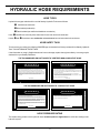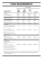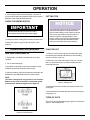
1
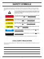
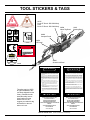
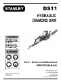
DS11 HYDRAULIC DIAMOND SAW WARNING To avoid serious injury or death Read the Manual Wear Eye Protection SAFETY, OPERATION AND MAINTENANCE SERVICE MANUAL Wear Ear Protection Wear Dust Mask 47351 Copyright © 2003, The Stanley Works SVCE/MAINT USA 22799 11/2003 Ver 1 Stanley Hydraulic Tools 3810 SE Naef Road Milwaukie OR 97267-5698 503-659-5660 FAX 503-652-1780 www.stanley-hydraulic-tools.com TABLE OF CONTENTS Safety Symbols and Precautions ........................................................................ 4 Tool Stickers and Tags ........................................................................................ 7 Hydraulic Hose Requirements ........................................................................... 8 HTMA Requirements ........................................................................................... 9 Operation ........................................................................................................... 10 Equipment Protection and Care ........................................................................ 17 Troubleshooting ................................................................................................ 18 Specifications .................................................................................................... 20 Accessories ....................................................................................................... 20 Service ............................................................................................................... 21 Parts Illustration ................................................................................................. 27 Parts List ............................................................................................................ 28 Chain Applications ............................................................................................ 29 Warranty ............................................................................................................. 30 SERVICING THE STANLEY DIAMOND SAW: This manual contains safety, operation, and routine maintenance instructions. Stanley Hydraulic Tools recommends that servicing of hydraulic tools, other than routine maintenance, must be performed by an authorized and certified dealer. Please read the following warning. WARNING SERIOUS INJURY OR DEATH COULD RESULT FROM THE IMPROPER REPAIR OR SERVICE OF THIS TOOL. REPAIRS AND / OR SERVICE TO THIS TOOL MUST ONLY BE DONE BY AN AUTHORIZED AND CERTIFIED DEALER. For the nearest authorized and certified dealer, call Stanley Hydraulic Tools at the number listed on the back of this manual and ask for a Customer Service Representative. 3 SAFETY SYMBOLS Safety symbols and signal words, as shown below, are used to emphasize all operator, maintenance and repair actions which, if not strictly followed, could result in a life-threatening situation, bodily injury or damage to equipment. This is the safety alert symbol. It is used to alert you to potential personal injury hazards. Obey all safety messages that follow this symbol to avoid possible injury or death. DANGER This safety alert and signal word indicate an imminently hazardous situation which, if not avoided, will result in death or serious injury. WARNING This safety alert and signal word indicate a potentially hazardous situation which, if not avoided, could result in death or serious injury. CAUTION This safety alert and signal word indicate a potentially hazardous situation which, if not avoided, may result in minor or moderate injury. This signal word indicates a potentially hazardous situation which, if not avoided, may result in property damage. NOTICE This signal word indicates a situation which, if not avoided, will result in damage to the equipment. IMPORTANT This signal word indicates a situation which, if not avoided, may result in damage to the equipment. Always observe safety symbols. They are included for your safety and for the protection of the tool. LOCAL SAFETY REGULATIONS Enter any local safety regulations here. Keep these instructions in an area accessible to the operator and maintenance personnel. 4 SAFETY PRECAUTIONS Tool operators and maintenance personnel must always comply with the safety precautions given in this manual and on the stickers and tags attached to the tool and hose. To avoid serious injury or death These safety precautions are given for your safety. Review them carefully before operating the tool and before performing general maintenance or repairs. Read the Manual Supervising personnel should develop additional precautions relating to the specific work area and local safety regulations. If so, place the added precautions in the space provided on page 4. Wear Eye Protection The DS11 Concrete Chain Saw will provide safe and dependable service if operated in accordance with the instructions given in this manual. Read and understand this manual and any stickers and tags attached to the tool and hoses before operation. Failure to do so could result in personal injury or equipment damage. Wear Ear Protection Wear Dust Mask 47351 • Establish a training program for all operators to ensure safe operation. • The operator must be familiar with all prohibited work areas such as excessive slopes and dangerous terrain conditions. • Do not operate the chain saw unless thoroughly trained or under the supervision of an instructor. • Always wear safety equipment such as goggles, ear, head protection, leg protection, gloves, snug fitting clothing and safety shoes at all times when operating the chain saw. • Do not overreach. Maintain proper footing and balnace at all times. • Do not inspect or clean the chain saw while the hydraulic power source is connected. Accidental engagement of the chain saw can cause serious injury. • Always connect hoses to the chain saw hose couplers before engergizing the hydraulic power source. Make sure all hose connections are tight. • Do not operate the chain saw at fluid temperatures above 140°F/60°C. Operation at higher temperatures can cause higher than normal temperatures at the chain saw which can result in operator discomfort. • Do not rely exclusively upon the safety devices built into the chain saw. As a chain saw user, several steps must be taken to keep your cutting jobs free from accident or injury: 1. With a basic understanding of kickbacks, you can reduce or eliminate the element of surprise. Sudden surprise contributes to accidents. 2. Keep a good firm grip on the chain saw with both hands, the right hand on the rear handle and the left hand on the front handle when operating the chain saw. Use a firm grip with thumbs and fingers encircling the chain saw handles. A firm grip helps reduce kickbacks and maintains control of the chain saw. Do not let go. 3. Make sure the area in which you are cutting is free of obstructions. 4. Cut at rated operating speeds (gpm). 5. Do not overreach or cut above shoulder height. 6. Only use replacement bars and chains specified by Stanley or the equivalent. • Make sure the chain guard is in place before operating the chain saw. 5 SAFETY PRECAUTIONS • Remove or control the water slurry to prevent yourself or others from slipping while cutting. • Provide adequate ventilation in closed areas when operating a gas or diesel hydraulic power source. • Always be well rested and mentally alert before operating the chain saw. • Do not allow bystanders near the chain saw when starting or cutting. • Do not start cutting until you have a clear work area and secure footing. • Keep all parts of the body away from the chain saw during operation. • Carry the chain saw with the tool deenergized and the bar and chain to the rear of your body. • Do not operate a chain saw that is damaged, improperly adjusted, or not completely and securely assembled. Make sure the chain stops moving when the control trigger is released. • Keep the handle dry, clean and free of hydraulic fluid. • Do not use the chain saw near energized transmission lines. • Turn off the power source or move the hydraulic control valve to neutral before setting the chain saw down. • Use a guide bar scabbard when transporting the chain saw. • Know the location of buried or covered electrical services before starting work. • To avoid personal injury or equipment damage, all chain saw repair, maintenance and service must only be performed by authorized and properly trained personnel. • Make sure the chain breaker and rivet spinner are securely mounted on flat, clean work surfaces. Check the mounting screws/bolts often. • Check all chain breaker and rivet spinner components regularly for wear and general condition. 6 TOOL STICKERS & TAGS E D 40 LPM @ 138 BAR EHTMA CATEGORY 30 LPM @ 138 B AR EHTMA CATEGORY 12535 11207 L WA 108 28409 29530 12535 Circuit “E” Decal - DS115000 Only 11207 Circuit “D” Decal - DS113000 Only 20588 Name Tag Decal 12412 Warning Decal 28409 Composit Decal 28323 CE Decal DANGER Failure to use hydraulic hose labeled and certified as non-conductive when using hydraulic tools on or near electric lines may result in death or serious injury. 28323 ELECTROCUTION HAZARD Failure to use hydraulic hose labeled and certified For proper and safe operation read owners manual as non-conductive when using hydraulic tools on and mwke sure that you have been properly or near electric lines may result in death or trained in correct serious injury.procedures required for work on or around electric lines. For proper and safe operation read owners manual and mwke sure that you have been properly Stanley Hydraulic Tools 3810 SE Naef Road Milwaukie, OR 97062 12412 trained in correct procedures required for work HAZARD on or around electric lines. Model 29530 Sound Level Decal DS11 20588 D A N G E R 1. FAILURE TO USE HYDRAULIC HOSE LABELED AND CERTIFIED AS NON-CONDUCTIVE WHEN USING HYDRAULIC TOOLS ON OR NEAR ELECTRICAL LINES MAY RESULT IN DEATH OR SERIOUS INJURY. BEFORE USING HOSE LABELED AND CERTIFIED AS NON-CONDUCTIVE ON OR NEAR ELECTRIC LINES BE SURE THE HOSE IS MAINTAINED AS NON-CONDUCTIVE. THE HOSE SHOULD BE REGULARLY TESTED FOR ELECTRIC CURRENT LEAKAGE IN ACCORDANCE WITH YOUR SAFETY DEPARTMENT INSTRUCTIONS. 2. A HYDRAULIC LEAK OR BURST MAY CAUSE OIL INJECTION INTO THE BODY OR CAUSE OTHER SEVERE PERSONAL INJURY. The safety tag (p/n 15875) at right is attached to the tool when shipped from the factory. Read and understand the safety instructions listed on this tag before removal. We suggest you retain this tag and attach it to the tool when not in use. A DO NOT EXCEED SPECIFIED FLOW AND PRESSURE FOR THIS TOOL. EXCESS FLOW OR PRESSURE MAY CAUSE A LEAK OR BURST. B DO NOT EXCEED RATED WORKING PRESSURE OF HYDRAU LIC HOSE USED WITH THIS TOOL. EXCESS PRESSURE MAY CAUSE A LEAK OR BURST. C CHECK TOOL HOSE COUPLERS AND CONNECTORS DAILY FOR LEAKS. DO NOT FEEL FOR LEAKS WITH YOUR HANDS. CONTACT WITH A LEAK MAY RESULT IN SEVERE PERSONAL INJURY. D A N G E R D DO NOT LIFT OR CARRY TOOL BY THE HOSES. DO NOT ABUSE HOSE. DO NOT USE KINKED, TORN OR DAMAGED HOSE. 3. MAKE SURE HYDRAULIC HOSES ARE PROPERLY CONNECTED TO THE TOOL BEFORE PRESSURING SYSTEM. SYSTEM PRESSURE HOSE MUST ALWAYS BE CONNECTED TO TOOL "IN" PORT. SYSTEM RETURN HOSE MUST ALWAYS BE CONNECTED TO TOOL "OUT" PORT. REVERSING CONNECTIONS MAY CAUSE REVERSE TOOL OPERATION WHICH CAN RESULT IN SEVERE PERSONAL INJURY. 4. DO NOT CONNECT OPEN-CENTER TOOLS TO CLOSED-CENTER HYDRAULIC SYSTEMS. THIS MAY RESULT IN LOSS OF OTHER HYDRAULIC FUNCTIONS POWERED BY THE SAME SYSTEM AND/ OR SEVERE PERSONAL INJURY. 5. BYSTANDERS MAY BE INJURED IN YOUR WORK AREA. KEEP BYSTANDERS CLEAR OF YOUR WORK AREA. 6. WEAR HEARING, EYE, FOOT, HAND AND HEAD PROTECTION. 7. TO AVOID PERSONAL INJURY OR EQUIPMENT DAMAGE, ALL TOOL REPAIR MAINTENANCE AND SERVICE MUST ONLY BE PERFORMED BY AUTHORIZED AND PROPERLY TRAINED PERSONNEL. I M P O R TA N T I M P O R TA N T READ OPERATION MANUAL AND SAFETY INSTRUCTIONS FOR THIS TOOL BEFORE USING IT. READ OPERATION MANUAL AND SAFETY INSTRUCTIONS FOR THIS TOOL BEFORE USING IT. USE ONLY PARTS AND REPAIR PROCEDURES APPROVED BY STANLEY AND DESCRIBED IN THE OPERATION MANUAL. USE ONLY PARTS AND REPAIR PROCEDURES APPROVED BY STANLEY AND DESCRIBED IN THE OPERATION MANUAL. TAG TO BE REMOVED ONLY BY TOOL OPERATOR. TAG TO BE REMOVED ONLY BY TOOL OPERATOR. SEE OTHER SIDE SEE OTHER SIDE SAFETY TAG P/N 15875 7 (shown smaller then actual size) HYDRAULIC HOSE REQUIREMENTS HOSE TYPES Hydraulic hose types authorized for use with Stanley Hydraulic Tools are as follows: Certified non-conductive Wire-braided (conductive) Fabric-braided (not certified or labeled non-conductive) Hose listed above is the only hose authorized for use near electrical conductors. Hoses and listed above are conductive and must never be used near electrical conductors. HOSE SAFETY TAGS To help ensure your safety, the following DANGER tags are attached to all hose purchased from Stanley Hydraulic Tools. DO NOT REMOVE THESE TAGS. If the information on a tag is illegible because of wear or damage, replace the tag immediately. A new tag may be obtained from your Stanley Distributor. D A N G E R D A N G E R 1 FAILURE TO USE HYDRAULIC HOSE LABELED AND CERTIFIED AS NON-CONDUCTIVE WHEN USING HYDRAULIC TOOLS ON OR NEAR ELECTRIC LINES MAYRESULT IN DEATH OR SERIOUS INJURY. FOR PROPER AND SAFE OPERATION MAKE SURE THAT YOU HAVE BEEN PROPERLY TRAINED IN CORRECT PROCEDURES REQUIRED FOR WORK ON OR AROUND ELECTRIC LINES. 3. DO NOT EXCEED HOSE WORKING PRESSURE OR ABUSE HOSE. IMPROPER USE OR HANDLING OF HOSE COULD RESULT IN BURST OR OTHER HOSE FAILURE. KEEP HOSE AS FAR AWAY AS POSSIBLE FROM BODY AND DO NOT PERMIT DIRECT CONTACT DURING USE. CONTACT AT THE BURST CAN CAUSE BODILY INJECTION AND SEVERE PERSONAL INJURY. 4. HANDLE AND ROUTE HOSE CAREFULLY TO AVOID KINKING, ABRASION, CUTTING, OR CONTACT WITH HIGH TEMPERATURE SURFACES. DO NOT USE IF KINKED. DO NOT USE HOSE TO PULL OR LIFT TOOLS, POWER UNITS, ETC. 2. BEFORE USING HYDRAULIC HOSE LABELED AND CERTIFIED AS NON-CONDUCTIVE ON OR NEAR ELECTRIC LINES. WIPE THE ENTIRE LENGTH OF THE HOSE AND FITTING WITH A CLEAN DRY ABSORBENT CLOTH TO REMOVE DIRT AND MOSISTURE AND TEST HOSE FOR MAXIMUM ALLOWABLE CURRENT LEAKAGE IN ACCORDANCE WITH SAFETY DEPARTMENT INSTRUCTIONS. 5. CHECK ENTIRE HOSE FOR CUTS CRACKS LEAKS ABRASIONS, BULGES, OR DAMAGE TO COUPLINGS IF ANY OF THESE CONDITIONS EXIST, REPLACE THE HOSE IMMEDIATELY. NEVER USE TAPE OR ANY DEVICE TO ATTEMPT TO MEND THE HOSE. 6. AFTER EACH USE STORE IN A CLEAN DRY AREA. SEE OTHER SIDE SEE OTHER SIDE SIDE 1 3 D O N O T R E M O V E T H I S TA G D O N O T R E M O V E T H I S TA G THE TAG SHOWN BELOW IS ATTACHED TO "CERTIFIED NON-CONDUCTIVE" HOSE SIDE 2 (shown smaller than actual size) D A N G E R D A N G E R 1 DO NOT USE THIS HYDRAULIC HOSE ON OR NEAR ELECTRIC LINES. THIS HOSE IS NOT LABELED OR CERTIFIED AS NON-CONDUCTIVE. USING THIS HOSE ON OR NEAR ELECTRICAL LINES MAY RESULT IN DEATH OR SERIOUS INJURY. 5. CHECK ENTIRE HOSE FOR CUTS CRACKS LEAKS ABRASIONS, BULGES, OR DAMAGE TO COUPLINGS IF ANY OF THESE CONDITIONS EXIST, REPLACE THE HOSE IMMEDIATELY. NEVER USE TAPE OR ANY DEVICE TO ATTEMPT TO MEND THE HOSE. 2. FOR PROPER AND SAFE OPERATION MAKE SURE THAT YOU HAVE BEEN PROPERLY TRAINED IN CORRECT PROCEDURES REQUIRED FOR WORK ON OR AROUND ELECTRIC LINES. 6. AFTER EACH USE STORE IN A CLEAN DRY AREA. 3. DO NOT EXCEED HOSE WORKING PRESSURE OR ABUSE HOSE. IMPROPER USE OR HANDLING OF HOSE COULD RESULT IN BURST OR OTHER HOSE FAILURE. KEEP HOSE AS FAR AWAY AS POSSIBLE FROM BODY AND DO NOT PERMIT DIRECT CONTACT DURING USE. CONTACT AT THE BURST CAN CAUSE BODILY INJECTION AND SEVERE PERSONAL INJURY. 4. HANDLE AND ROUTE HOSE CAREFULLY TO AVOID KINKING, CUTTING, OR CONTACT WITH HIGH TEMPERATURE SURFACES. DO NOT USE IF KINKED. DO NOT USE HOSE TO PULL OR LIFT TOOLS, POWER UNITS, ETC. D O N O T R E M O V E T H I S TA G D O N O T R E M O V E T H I S TA G THE TAG SHOWN BELOW IS ATTACHED TO "CONDUCTIVE" HOSE. SEE OTHER SIDE SEE OTHER SIDE SIDE 1 SIDE 2 (shown smaller than actual size) HOSE PRESSURE RATING The rated working pressure of the hydraulic hose must be equal to or higher than the relief valve setting on the hydraulic system. 8 HTMA REQUIREMENTS Tool Category Hydraulic System Requirements 20Lpm at 138bar BHTMA CATEGORY 30Lpm at 138bar BHTMA CATEGORY Type I Type II 40Lpm at 138bar EHTMA CATEGORY Type III 4-6gpm 7-9gpm 10.5-11.6 gpm 11-13 gpm (at the power supply outlet) 2000 psi 2000 psi 2000 psi 2000 psi System relief valve setting 2100-2250 psi Flow rate Tool Operating Pressure (at the power supply outlet) Maximum back pressure (at tool end of the return hose) (15-23 lpm) (26-34 lpm) (138 bar) (138 bar) 2100-2250 psi (145-155 bar) 200 psi Measured at a max. fluid viscosity of: 400 ssu* (138 bar) 2100-2250 psi (42-49 lpm) (138 bar) 2100-2250 psi (145-155 bar) (145-155 bar) (145-155 bar) 200 psi 200 psi 200 psi (14 bar) (14 bar) (36-44 lpm) (14 bar) (14 bar) (at min. operating temperature) (82 centistokes) (82 centistokes) 400 ssu* 400 ssu* 400 ssu* Temperature Sufficient heat rejection capacity to limit max. fluid temperature to: 140° F (60° C) 140° F (60° C) 140° F (60° C) 140° F (60° C) Min. cooling capacity at a temperature difference of between ambient and fluid temps 3 hp (2.24 kW) 40° F (22° C) 5 hp (3.73 kW) 40° F (22° C) 6 hp (4.47 kW) 40° F (22° C) 7 hp (5.22 kW) 40° F (22° C) 25 microns 18 gpm (68 lpm) 25 microns 25 microns 25 microns 30 gpm (114 lpm) 35 gpm (132 lpm) 40 gpm (151 lpm) 100-400 ssu* 100-400 ssu* (82 centistokes) (82 centistokes) (at max. expected ambient temperature) NOTE: Do not operate the tool at oil ° F (60° C). Operation temperatures above 140 at higher temperatures can cause operator discomfort at the tool. Filter Min. full-flow filtration Sized for flow of at least: (For cold temp. startup and max. dirt-holding capacity) Hydraulic fluid Petroleum based (premium grade, anti-wear, non-conductive) Viscosity (at min. and max. operating temps) (20-82 centistokes) NOTE: When choosing hydraulic fluid, the expected oil temperature extremes that will be experienced in service determine the most suitable temperature viscosity characteristics. Hydraulic fluids with a viscosity index over 140 will meet the requirements over a wide range of operating temperatures. (20-82 centistokes) 100-400 ssu* (20-82 centistokes) 100-400 ssu* (20-82 centistokes) NOTE: These are general hydraulic system requirements. See tool Specification page for tool specific requirements. 9 OPERATION PREOPERTION PROCEDURES CHECK THE POWER SOURCE 1. Using a calibrated flow meter and pressure gauge, make sure the hydraulic power source develops a flow of 7-9 gpm/ 26-34 lpm at 2000 psi/140 bar. 2. Make certain that the power source is equipped with a relief valve set to open at 2100-2250 psi/145-155 bar. 4. If the water pressure is below 35 psi/2.4 bar, make the required adjustments to the water supply. If the required pressure cannot be achieved, you must use the Stanley Electric Water Pump Kit (Part Number 26020 or the Power Unit Water Pump Kit Part Number 29361). CHECK CHAIN AND BAR ADJUSTMENT CONNECT HYDRAULIC HOSES 1. Check the chain tension often during operation, expecially during the first 1/2 hour when using a new chan. Adjust the chain accordingly when it becomes loose. Follow the prcedures contained in the Mainenance and Adjustements section of this manual. 1. Wipe all hose couplers with a clean lint-free cloth before making connections. If necessary, use a light-weight penetrating oil in a spray can to clean the hose couplers before each connection. 2. Make sure the chain does not exceed a clearance of 1/4 in./6 mm from the bar (see figure 2). Exceeding the maximum clearance increases the chance of the chain being dislodged from the bar groove. 3. Make certain that the power source return pressure does not exceed 250 psi/17 bar. 2. Connect the hoses from the hydraulic power source to the chain saw fittings or quick disconnects. It is a good practice to connect return hoes first and disconnect them last to minimize or avoid trapped pressure within the chain saw. Max 1/4” 3. Observe the arrow on the couplers to ensure that the flow is in the proper direction. the female coupler on the chain saw is the inlet (pressure) coupler. Figure 2. Maximum Chain Clearance 4. Move the hydraulic circuit control valve to the “ON” position to operate the chain saw. NOTE: If uncoupled hoses are left in the sun, pressure increase inside the hoses might make them difficult to connect. Whenever possible, connect the free ends of the hoses together. 3. Make sure the bar attaching nuts are fully tightened and the chain guard is in place. CHECK CHAIN SEGMENT WEAR 1. Using adjustable calipers, measure several chain segments as illustrated in Figure 3. CONNECTING TO A WATER SUPPLY 1. Using a standard garden hose, connect the DS11 to a city or auxiliary water supply. 2. Holding the saw away from your body, turn the saw on and read the water pressure at the water gauge. Water pressure must be at least 35 psi/2.4 bar to avoid damage to the saw bar and chain. Figure 3. Chain Segment Wear 3. If you plan on operating the chain saw in freezing weather, make sure you purge all the water from the system after each use. 10 OPERATION 2. If the average measurement is less than 1/16-inch/1.6 mm, then the chainmust be replaced. Refer to your Service Manual for chain replacement procedures. CUTTING TIPS CHECK THE WATER SUPPLY NOTICE IMPORTANT The following are general cutting procedures and techniques. Differences in the terrain and the type of material being cut will make this information more or less valid for particular areas. For advice on specific cutting problems or techniques, consult your local Lynx Representative. He/she can often provide information that will make your work safter and more productive. Chain and bar damage will occur if the chain saw operates without the proper water supply. 1. Always have water running before starting the chain saw. 2. Water flow must be 4 gpm/15 lpm at 50 psi/3.5 bar minimum. OPERATING PROCEDURES NEW SAW CHAIN BREAK-IN 1. Always make sure the bar and sprocket are in good condition. 2. Turn on the water supply. PLAN THE CUT 1. Plan your cuts to prevent injury to yourself and to keep from pinching the saw bar and chain as a result of falling pieces of concrete, brick, etc. 2. Make your cuts in the order shown in Figure 5, starting with cut 1 (base horizontal cut) and proceeding with the remaining three cuts. 3. Operate the chain saw for two minutes (away from the intended cut) and then check the chain tension. 4. Adjust accordingly using the procedures contained in the Maintanence and Adjustments section of this manual. NOTE: The chain is designed to only operate in one direction. Make sure the chain is installed so the bumper guard proceeds each diamond segment. (See figure 4). Figure 5. Making Cuts 3. Outline the concrete area with a permanent marker for a visual guide. 4. Know what kind of material and how much reinforcing you are going to cut. TYPES OF CUTS The LCC31 can be operated using the types of cuts shown in Figure 6. When making cuts: Figure 4. Chain Direction 11 OPERATION DOWN CUT PLUNGE CUT UP CUT Figure 6. Types of Cuts (chain guard removed for clarity) 1. Do not use a cutting force in excess of 45 lbs/20 kg. Excessive force causes the chain to slow down or stall and causes premature wear of the saw bar and chain. 2. Always maintain a high chain speed. High chain speeds produce the best results. 3. Avoid aggressive/heavy plunge forces. Aggressive plunge force creates spalling of the concrete when the saw bar and chain exits and causes premature bar and chain wear. COLD WEATHER OPERATION If the saw is to be used during cold weather, preheat the hydraulic fluid at low power source speed. When using the normally recommended fluids, fluid should be at or above 50°F/10°C (400 ssu/82 centistokes) before use. Damage to the hydraulic system or chain saw can result from use with fluid that is too viscous or thick. 12 MAINTENANCE & ADJUSTMENTS evenly. Refer to the saw bar disassembly procedures in the Service Manual for further details. GENERAL MAINTENANCE TIPS CHAIN TENSION ADJUSTMENT Several simple maintenance tasks which, if performed, can keep a chain saw operating at a high level of efficiency. Routine maintenance also keeps replacement costs down on the parts of the chain saw, which occasionally wear out. Correct chain tension is very important throughout the life of the chain. Check the chain tension often during use (when the chain saw is stopped and the saw bar and chain have cooled off). The chain should move easily around the saw bar when pulled by hand. To adjust the chain tension: If any chain saw disassembly is required, refer to the Service Manual. 1. Turn off the water and power supplies. SAW BAR RAIL 2. Loosen the two saw bar attachment nuts (Item 62, Parts Illustration). A quick check can be made to determine if saw bar rail or chain segment wear exists. Figure 7 shows a worn saw bar rail. 3. Using the saw bar adjustment screw (Item 65, Parts Illustration), tighten the chain until you are still able to rotate it one full revolution by hand (Figure 9). Figure 9. Pulling the Chain 4. Pull the chain around the saw bar to make sure it properly fits the sprocket and saw bar. The chain should be easily pulled. 5. Fully tighten the two saw bar attachment nuts. NOTE: Adjust the chain tension each time the drive link tang hangs fully exposed from the groove at the bottom of the saw bar (Figure 10). Figure 7. Rail Wear If the saw bar rails are worn, use a flat file and dress each one until it is flat and square with the side of the saw bar (Figure 7). Max 1/4” Also make sure the saw bar is perfectly straight. If bows or bends are present in the saw bar, it must be replaced before dressing any rail. ROTATING THE SAW BAR Figure 10. Exposed Drive Link Tang Maximum saw bar life can be achieved by occasionally turning the bar over so the top and bottom bar surfaces wear 13 MAINTENANCE & ADJUSTMENTS SERVICING THE CHAIN The following procedures explain how to break a chain using Stanley’s bench mounted chain breaker (part number 20858) to remove a worn or damaged segment. 1. Mount the chain breaker flush with the side or front of a flat, clean work surface (Figure 11). Figure 11. Chain Breaker Mounting Figure 13. Inserting the Chain NOTE: The Stanley chain breaker is only designed to remove rivet heads from the connecting links, not from a chain segment. The rivet heads shown in the shaded areas of Figure 12 are the only ones that can be removed. 3. Position the rivet head you want removed directly under the chainbreaker punch and then pull the handle down far enough to remove the rivet (Figure 14). Do not use excessive force. Figure 12. Removable Rivet Heads 2. Place the chain (the portion that you want broken) into the slot of the anvil pushing it forward until the bottom connecting link is flush with the far side of the slot (Figure 13). Figure 14. Removing a Rivet 14 MAINTENANCE & ADJUSTMENTS REPLACING THE CHAIN BREAKER PUNCH If the chain breaker punch (part number 22801) becomes worn or damaged, use the following prcedures for replacement. 1. Remove the punch by loosening the set screw (Figure 15). Figure 17. Rivet Spinner Mounting 2. Lay the chain across the plastic chain supports and then rotate the supports so the rivet head is centered between the take-up handle pocket and the spinner anvil (Figure 18). Figure 15. Removing the Punch 2. Insert a new punch into the holder and push it up until it is fully seated (Figure 16). Secure the punch to the chain breaker holder by fully tightening the set screw. Figure 18. Positioning the Chain 3. Turn the take-up handle until the chain is tight against the spinner anvil (Figure 19). Take-up Handle Rivet Spinner Crank Figure 16. Replacing the Punch SPINNING RIVETS Figure 19. Securing the Chain The following procedures explain how to spin rivets using Stanley’s bench-mounted rivet spinner (part number 20857) to assembly the chain. 1. Mount the rivet spinner flush with the side or front of a flat, clean work surface (Figure 17). 15 MAINTENANCE & ADJUSTMENTS 4. turn the rivet spinner crank a few times to center the rivet hub in the spinner anvil (Figure 20). NOTE: the rivet spinner is equipped with oiling chambers and should be maintained periodically with a light-weight oil (Figure 23). Take-up Handle Rivet Spinner Crank Figure 20. Centering the Rivet Hub 5. Apply a few drops of oil to the rivet hub (Figure 21). Figure 23. Spinner Oiling Chambers Figure 21. Applying the Oil 6. Turn the spinner crank while slowly running the take-up handle inward (approximately one full revolution) until the rivet head is formed (Figure 22). NOTE: The take-up handle provides pressure while the spinner anvil forms the rivet head. Figure 22. Forming a Rivet Head 16 TOOL EQUIPMENT & CARE NOTICE In addition to the Safety Precautions on page in this manual, observe the following for equipment protection and care. • Make sure all couplers are wiped clean before connection. • The hydraulic circuit control valve must be in the “OFF” position when coupling or uncoupling hydraulic tools. Failure to do so may result in damage to the quick couples and cause overheating of the hydraulic system. • Always store the tool in a clean dry space, safe from damage or pilferage. • Make sure the circuit PRESSURE hose (with male quick disconnect) is connected to the “IN” port. The circuit RETURN hose (with female quick disconnect) is connected to the opposite port. Do not reverse circuit flow. This can cause damage to internal seals. • Always replace hoses, couplings and other parts with replacement parts recommended by Stanley Hydraulic Tools. Supply hoses must have a minimum working pressure rating of 2500 psi/172 bar. • Do not exceed the rated flow (see Specifications) page in this manual for correct flow rate and model number. Rapid failure of the internal seals may result. • Always keep critical tool markings, such as warning stickers and tags legible. • Tool repair should be performed by experienced personnel only. • Make certain that the recommended relief valves are installed in the pressure side of the system. • Do not use the tool for applications for which it was not intended. 17 TROUBLESHOOTING CHAIN SAW TROUBLESHOOTING Excessive vibration and cuts rough. Loose chain tension. Excessive feed force. Retension the chainl. Reduce feed force. Chain saw will not cut straight. Operator feed force not applied directly over centerline of saw. Accumulated saw bar wear and uneven chain segment profile wear. move left hand closer to centerline of saw bar. Turn the saw bar over and dress rails square. Replace the saw bar and chain. Loss of power. Drive sprocket slipping on Trantorque® adapter. Adjust and tighten Trantorque® adapter, (35 ft lbs/47 Nm). Chain saw does not run. Power source not functioning. Check power source for proper flow and pressure (7-9 gpm/26-34 lpm @ 2000 psi/140 bar). Remove obstruction. Disassemble the chain saw and inspect for damage. Coupler or hoses are blocked. Mechanical failure. Chain saw runs backwards. Pressure and return hoses reversed. Connect for proper flow direction. Motor shaft must rotate clockwise. Trigger is hard to press. Pressure and return hoses reversed. Back pressure too high. Connect to proper flow direction. Motor shaft must rotate clockwise. Should not exceed 250 psi/17 bar @ 9 gpm/34 lpm measured at the end of the chain saw’s operating hoses. Fluid leakage around drive sprocket. Motor shaft seal failure. Replace as required. Fluid leakage between the rear gear housing and the chain saw adaptor. Motor face seal failure. Replace as required. Fluid leakage between the valve handle and the extension housing. Oil tube seal failure. Replace as required. Fluid leakage between the extension housing assembly and the chain saw adaptor. Oil tube seal failure. Replace as required. Chain saw cuts slow. Insufficient hydraulic fluid flow or low relief valve setting. Adjust proper hydraulic fluid flow to proper gpm. For optimum performance, adjust relief valve to 21002250 psi/145-155 bar. 18 TROUBLESHOOTING CHAIN SAW TROUBLESHOOTING CONTINUED Chain saw cuts slow. Back pressure too high. Loss of diamond segment side clearance. Hydraulic fluid mixed in water supply. Chain segment dulled because of continuous use in hard material or rebar. Wire edged bar rails. Check motor for leaks. Redress segment by cutting in abrasive material (i.e., concrete, buildblock, etc.). NOTE: This indicates that the wrong chain is being used. Scale down to a lower numbered chain. Dress rails square. Segment(s) broken or missing from chain. Remove and repair broken segment or replace chain. Wrong chain for application. Excessive vibration and cuts rough. Should not exceed 250 psi/17 bar @ 9 gpm/34 lpm measured at the end of the chain saw’s operating hoses. Replace the chain. 19 SPECIFICATIONS Cutting Depths ............................................................................................................................. 15 or 18 inch / 38 or 46 cm Bar Lengths ................................................................................................................................. 15 or 18 inch / 38 or 46 cm Input Flow Range DS113000 ............................................................................................................................ 7-9 gpm / 26-34 lpm DS115000 .................................................................................................................................... 12 gpm/45 lpm Input Pressure ............................................................................................................................................2000 psi / 140 bar Chain Type ....................................................................................................................................................... 3/8 inch Pitch Weight (with bar) ............................................................................................................................................ 26 lbs / 11.8 kg Length ...................................................................................................................................... 35 or 38 inches / 89 or 97 cm Width .......................................................................................................................................................... 9 inches / 23 cm Lubrication / Cooling ............................................................................................................... Internal Water Channels in Bar Porting ........................................................................................................................................................... -8 SAE O-Ring Connection .................................................................................................... 3/8 inch Flush-Face Quick Disconnect Coupler Hose Whips .....................................................................................................................................................................Yes ACCESSORIES Chain Repair Spinner ................................................................................................................................................... 20857 Diamond Chain Repair Breaker .................................................................................................................................... 20858 Diamond Chain Repair Kit (inludes p/n 20857 & 20858) ................................................................................................ 20856 Diamond Chain Service Kit .............................................................................................................. (sub p/n 20857 or 20858) Wall Walker (Standard Equipment on Newer Models) ................................................................................................... 23176 Drive Sprocket .............................................................................................................................................................. 20470 Replacement Nose Sprocket ........................................................................................................................................ 22800 Carrying Case .............................................................................................................................................................. 28232 Sprocket Wrench ......................................................................................................................................................... 23517 Replacement Punch ..................................................................................................................................................... 22801 Water Pump Kit (115/230 Volt / 60 Hz) ......................................................................................................................... 26020 Water Pump Kit (220/380/440 Volt /50 Hz) ................................................................................................................... 26237 HP1 Power Unit Water Pump Kit .................................................................................................................................. 29361 3/8 inch Flush-Face Coupler Set .................................................................................................................................. 03971 1/2 inch Flush-Face Coupler Set .................................................................................................................................. 03974 25 feet, 1/2 inch Dual Hose with Flush-Face Couplers .................................................................................................. 31972 50 feet, 1/2 inch Dual Hose with Flush-Face Couplers .................................................................................................. 31848 15 inch Bar, Sprocket Nose .......................................................................................................................................... 30305 18 inch Bar, Sprocket Nose .......................................................................................................................................... 30306 Ultra-32, Sealed Chain for 15 inch Bar .......................................................................................................................... 56801 Pinnacle-32, Sealed Chain for 15 inch Bar .................................................................................................................... 56803 Ultra-37, Sealed Chain for 18 inch Bar .......................................................................................................................... 56802 Pinnacle-32, Sealed Chain for 18 inch Bar .................................................................................................................... 58632 Speed Hook Kit ............................................................................................................................................................ 39496 20 SERVICE INTRODUCTION MOTOR REMOVAL, DISASSEMBLY, INSPECTION, CLEANING, REPLACEMENT & ASSEMBLY Good maintenance practice keeps the chain saw on the job and increases its service life. the most important maintenance practice is to keep the hydraulic fluid clean at all times. Contaminated hydraulic fluid causes rapid wear and/or failure of internal parts. REMOVAL 1. Remove the two 3/8-inch nuts and plain washers securing the chain guard to the chain saw adaptor. Remove the guard. Follow the procedure contained in the Hydraulic System Requirements section of this manual to ensure peak performance from the chain saw. 2. Remove the chain and saw bar. Never disassemble the chain saw unless proper troubleshooting procedures have isolated the problem to an internal part. Then, disassemble the chain saw only to the extent necessary to replace the defective part. 3. Clamp the drive sprocket (a chain type locking wrench works best) and then loosen the Trantorque® adaptor securing the drive sprocket to the motor shaft. 4. Remove the drive sprocket and the Trantorque® adaptor. NOTE: Keep contaminants such as dirt and grit away from internal parts at all times. 5. Remove the four capscrews securing the chain saw adaptor, valve handle and extension housing together. Seperate these assemblies. Always determine and correct the cause of the problem prior to assembly. Further wear and chain saw failure can result if the original cause is not corrected. 6. Insert a hooked instrument through the oil tubes in the chain saw adaptor and valve handle (if necessary) and then pull them out. Take care to avoid damaging the oil tube bores in the chain saw adaptor and valve handle. PRIOR TO DISASSEMBLY 7. Remove the two oval head machine screws to allow the motor to be withdrawn from the chain saw adaptor. 1. Clean the exterior of the chain saw. 2. Obtain Seal Kit (part number 22798) to replace all seals exposed during disassembly. Note the orientation of the seals before removing them. Install new seals the same way they were removed. MOTOR DISASSEMBLY 1. Place the motor in a vise (with soft jaws or v-blocks) around the bearing end. Make sure the output shaft faces down. PRIOR TO ASSEMBLY 2. Remove the eight 1/4-20 x 1-3/4-inch / 44 mm capscrews securing the rear gear housing to the chain saw adaptor. 1. Clean all parts with a degreasing solvent. 3. Using a flat-bladed screwdriver or similar tool, gently and evenly pry all around the groove between the front bearing housing and the rear gear housing. DO NOT tilt the rear gear housing or pry on the flat surface inside the surrounding groove. Damage to the sealing surfaces can result. 2. Make sure all seals that were exposed have been replaced with new parts. 3. Apply clean grease or o-ring lubricant to all parts during assembly. NOTE: The gears and idler shaft might remain in the rear gear housing. Do not drop or damage them. 4. Carefully lift the rear gear housing from the front bearing housing. 21 SERVICE 5. Remove the two gears, idler shaft and needle roller. Gear Chamber 6. Remove the large face seal o-ring being careful not to damage the o-ring grooves or surrounding surfaces. The chamber bores and bottoms around the shaft bushings should be polished and smooth. The flat surface surrounding the gear chambers and bolt holes should be flat and free of nicks which could cause misalignment or leaks. 7. To remove the motor shaft from the front bearing housing, remove the large retaining ring securing the ball bearing/ keeper. Place the housing on a flat surface with clearance for bearing removal. Push on the small end of the motor shaft until the shaft and bearing slides free. Be careful not to bend the motor shaft. Gears The gears should have straight tips without nicks, square tooth ends and smooth even polish on the teeth and end surfaces. Check for cracks at the groove in the drive gear bore. 8. The ball bearing should be removed from the motor shaft only if it must be replaced because damage can occur during removal. To remove the bearing from the motor shaft, remove the small retaining ring securing the seal race spacer the large retaining ring covering the bearing and then press on the end of the motor shaft while supporting the outer race of the bearing. Discard the bearing. Front Bearing Housing The surface near the gears hould show two overlapping polished circles without a step and should not be rough or grooved. The bore for the seal and bearing keeper should be smooth and free from nicks and scratches or leakage might occur. 9. Remove the retaining ring at the bottom of the ball bearing bore to service the motor shaft seal. Motor Shaft 10. To remove the seal liner and associated parts, insert the small end of the motor shaft through the seal liner. Place a rag across the gear face of the front bearing retainer and blow air though the small diameter motor shaft bearing. Use a shop air nozzle to force the seal liner onto the motor shaft for removal. The shaft diameter at the bearing and seal locations must be smooth. Grooves, roughness or a reduced diameter indicate fluid contamination. Grit particles may have been imbedded in the bushings grinding into the hardened shaft. If abnormal shaft wear as a bove occurs (in excess of normal polishing), both the seal and associated bearings/bushings must be replaced. 11. Remove the bushings using Collet (part number 11930) and Actuator Pin (part number 05067) along with Slide Hammer (part number 11931). Check the hydraulic system for excess contamination in the fluid and for filter condition. Operating conditions might require changing from a 25 micron filter to an oversized 10 micron filter. CLEANING & INSPECTION Inspect and clean all parts as follows: Bushings 1. Assemble the seal gland assembly by installing the outside diameter o-ring and quad ring as shown on the parts illustration. Place idler shaft through the seal gland, then loosely position the assembly in the seal bore of the front bearing housing (quad ring side down). Then carefully push the seal gland into place. Install the retaining ring. Remove the idler shaft. The inside of the bushings should be gray with some bronze showing through. If a significant amount of yellow-bronze shows, bushing replacement is required. Inspect the motor shaft corresponding wear and replace as required. 2. To install the ball bearing on the motor shaft, support the ball bearing inner race and press the motor shaft through the bearing inner race. Place a new o-ring on the motor shaft, adjacent to the bearing inner race, slide the seal race over 1. Clean all parts with a degreasing solvent. 2. Blow dry all parts with compressed air and wipe clean. Use only lint-free cloths. 22 SERVICE the shaft, chamfered end first and secure with the retaining ring. It may be necessary to slide a deep socket or tube over the motor shaft to depress the o-ring and retaining ring so that the retaining ring end engages its groove. 10. When the new parts are installed, it might be necessary to “break-in” the motor. After the chain saw has been assembled without the guard, bar and chain, the motor can be broken-in as follows: NOTE: Some motor shafts may have two retaining ring grooves. The inner most groove is to be used. WARNING 3. Install the bushings using Bearing Pusher (part number 11918). The following procedures can be hazardous. Failure to heed the instructions could result in serious injury. 4. Place the front bearing housing assembly on a smooth clean arbor press surface (protected from damage) with the large bearing bore facing up. Position the part so a clearance hole exists for inserting the motor shaft. a. Make sure the hydraulic power source is running at the lowest gpm/lpm rate it can while still producing full pressure. 5. Apply grease to the motor shaft and keyway, then insert it through the shaft seal. Using Bearing Pusher (part number 00850), or a sleeve/socket with a diameter slightly smaller than the outside diameter of the ball bearing, press the bearing assembly into place. Press only on the outer race. Place the o-ring in the housing bore adjacent to the bearing outer race. Fill the bearing cavity with lubricating oil. Install the keeper using the bearing pusher as above and secure the assembly with the retaining ring. b. Grasp the chain saw firmly in a bench vise and place the correct size wrench on the Trantorque® adaptor. c. Connect the hydraulic power source to the chain saw and then turn the power source valve to the “ON” position. d. With a firm grip on the chain saw and wrench, SLOWLY squeeze the trigger to activate the chain saw. 6. Install the needle roller in the keyway of the motor shaft. Use a small amount of grease to keep the needle roller in place. Slide the drive gear over the needle roller and motor shaft. Install the idler shaft and gear. e. Turn the motor shaft both against and with the direction of rotation. 7. Apply grease to the face seal o-ring groove and then install the o-ring. g. Activate the chain saw to determine that the motor starts and runs freely. NOTE: Make sure the dowel pins and shafts are aligned during installation. h. If the motor is not starting or running freely, carefully repeat the break-in procedures until the motor performs satisfactorily. f. Release the trigger and remove the wrench. REPLACEMENT IMPORTANT 1. Push the motor into the chain saw adaptor assembly. Do not force parts together. 2. Align the motor mounting holes and then secure it using two 5/16-18 x 3/4 inch / 18 mm screws and 242 Loctite. 8. Note the screw hole pattern on the front and rear housings. They will only assembly one way. With all parts aligned, carefully slide the rear gear housing over the gears until it contacts the front bearing housing assembly. 3. Install new o-rings on the oil tubes and then install them in the chain saw adaptor and valve handle. Align with the extension housing and press together. Secure all parts using the four capscrews. 9. Turn the motor shaft manually to check for free rotation. Install the eight 1/4-20 x 1-3/4 inch / 44 mm capscrews. then recheck rotation. NOTE: DO NOT lubricate or clean the drive sprocket or Trantorque® adaptor. 23 SERVICE 4. Place the drive sprocket on the Trantorque® adaptor and install the assembly on the shaft so the shaft extends completely through the bore. ASSEMBLY 5. Properly position the drive sprocket and then hand tighten the Trantorque® adaptor until the drive sprocket begins to snug up. 2. Push the valve cap onto the valve stem, then thread the assembly into the top of the valve handle assembly. 6. Make any fine adjustments and then fully tighten the Trantorque® adaptor to a torque value of 200 inch lbs / 22.6 Nm. Use chain-type vise grip pliers to keep the sprocket from rotating as you tighten the Trantorque® nut. 7. Replace the chain guard and then secure it to the chain saw adaptor using two 3/8 inch nuts and plain washers. 8. Perform the Chain Tension Adjustment procedure. VALVE SPOOL DISASSEMBLY & ASSEMBLY DISASSEMBLY 1. Drive out the 1/4-inch roll pin securing the trigger to the valve handle assembly. Depress the safety catach and remove the triggers through the top of the valve handle. NOTE: It is not always necessary to drive the roll pins completely out of the valve handle to allow removal of parts. 1. Lubricate and install the quad ring in the valve cap bore. 3. Install the coil spring and the port plug into the bottom of the valve handle. 4. Line up the trigger and spacer with the pivot by inserting a 1/4-inch / 6 mm diameter punch into the valve handle (to maintain alignment while driving the roll pin into the handle.). Install the 1/4-inch roll pin in the trigger pivot hole. 5. Replace the safety catch (if previously removed). Place the torsion spring on the boss of the safety catch with the spring tab on the top of and facing the back of the catch as shown in the parts list illustration. 6. Place the safety catch in the valve handle and align the holes using a 3/16-inch / 5 mm diameter punch. 7. Install the 3/16 x 1-3/8-inch roll pin. 8. Push down on the spring tab until it snaps in place under the safety catch. 9. Check the safety catch and trigger mechanism for proper operation. The trigger must not activate the chain saw without the operator first depressing the safety catch. EXTENSION HOUSING DISASSEMBLY & ASSEMBLY The safety catch can be removed at this time by driving out the 3/16-inch roll pin with a 3/16-inch / 5 mm diameter punch. It is not necessary to remove the safety catch to service the On/Off valve. DISASSEMBLY 2. Remove the valve cap from the top of the handle. Remove the quad ring from the valve cap bore. 1. Remove the four hex socket head capscrews the chain saw adaptor and valve handle to the extension housing. 3. Pull the On/Off valve out through the top of the valve handle. 2. Carefully remove the o-ring plug to release the spring and water valve. 4. Remove the port plug from the bottom of the valve handle. The coil spring will drop out in your hand. 3. Remove the spring and water valve. 5. Carefully clean and inspect the valve spool and its bore in the valve handle. The valve spool and bore should have a polished appearance without scoring or deep scratches. Excessive wear indicates contaminated fluid in the hydraulic system. 4. Remove the two seals from inside the extension housing valve bore. 5. Carefully clean and inspect the water valve and its bore in the extension housing. The water valve and bore should have a polished appearance without scoring or deep scratches. 24 SERVICE Excessive wear indicates contaminated water. ASSEMBLY 1. Lubricate and insert two new seals into the extension housing. NOTE: Make sure the innermost seal (quad ring) is not twisted within its groove. 2. Insert the water valve into the extension housing. 3. Insert the spring into the valve counterbore. Figure 25. Removing the Old Nose Sprocket 4. Complete the assembly by installing the o-ring plug. 3. Remove the new nose sprocket clips and fold back the top portion of the insertion card being careful not to remove or disturb the components (Figure 26). 5. Secure the extension housing to the valve handle and chain saw adaptor using the four hex socket head capscrews. NOTE: Before proceeding to the Nose Sprocket Disassembly, order a new Stanley Nose Sprocket, part number 22800. NOSE SPROCKET DISASSEMBLY & ASSEMBLY Figure 26. Preparing the New Nose Sprocket 4. With a flat blade screwdriver in the bar nose rails, slide the nose sprocket assembly into position aligning the six holes in the bar nose with the six holes in the nose sprocket assembly without removing the components from the card (Figure 27). DISASSEMBLY 1. Using Stanley’s bench mounted chain breaker, line up the 1/4-inch hole in the side of the chainbreaker anvil with the chain breaker punch. Punch out the six nose sprocket rivets (Figure 24). Figure 27. Installing the New Nose Sprocket Figure 24. Punching out Nose Sprocket Rivets 5. Insert six nose rivets into theholes and then hold them with your thumb. Remove the screwdriver and slide out the insertion card. 2. Insert a straight blade screwdriver to spread the bar nose rails just enough to remove the old nose sprocket. Use a rag or paper towel to clean the nose sprocket area (Figure 25). 25 SERVICE NOTE: On used bars the nose rails might tend to spread apart. Use a small clamp if necessary to hold the rails together. 6. With the bar and rivets solidly supported on a strong flat steel surface, carefully peen the rivet heads down with the flat end of a hammer. Be careful to only hit the rivet head. Do not hit the bar body (this will pinch the nose sprocket). Rivet heads must completely fill the countersinks in the bar body and be snug and secure while still allowing the sprocket to freely turn (Figure 28). Figure 28. Replacing the Rivets 7. using a flat file, shave the rivet heads to a uniform height that is as close to the bar body as possible (Figure 29). Figure 29. Filing the Rivets 26 62 61 80 81 60 82 64 27 69 57 73 65 84 86 63 59 71 58 51 77 34 35 36 78 72 79 33 72 44 50 48 46 49 44 75 76 23 45 74 47 44 27 32 66 22 47 66 67 18 70 30 37 25 26 40 41 35 15 14 13 12 43 83 38 31 MOD EL/S N IN FO 42 67 17 16 53 54 55 68 28 52 39 19 56 21 20 85 29 10 9 11 7 O IL IN 8 3 5 4 6 3 24 2 1 DS11 PARTS ILLUSTRATION DS11 PARTS LIST ITEM 1 2 3 4 5 6 7 8 9 10 11 12 13 14 15 16 17 18 19 20 21 22 23 24 25 26 27 28 29 30 31 32 33 34 35 36 37 38 39 40 41 42 43 44 45 46 47 P/N 25688 23756 00208 06835 06316 06838 06840 06839 00713 00178 21417 350771 00171 00669 19884 00170 03227 06881 20466 23752 12119 02905 03104 03110 00633 01211 03280 20472 20588 03278 22701 31804 22707 02920 22704 01605 01219 340045 00112 02931 01604 02925 28552 20459 00787 35963 07226 06830 09437 03010 02916 20497 23755 00175 00174 20453 00961 QTY 1 1 8 1 4 1 1 1 2 1 1 1 1 1 1 1 1 1 1 1 1 1 1 1 1 1 1 1 1 1 1 1 1 1 1 2 1 1 1 1 2 1 1 1 1 1 2 2 1 1 1 1 1 8 2 1 2 DESCRIPTION Motor Assy - Land Model DS113000 Motor Assy - U/W Model DS115000 Capscrew, 1/4-20 x 1-3/4 Rear Gear Housing Bushing Drive Gear Idler Shaft Idler Gear Dowel Pin O-Ring* Front Bearing Housing O-Ring* (DS113000) O-Ring* (DS115000) Quad Ring* Seal Gland Retaining Ring Needle Roller (DS113000) Needle Roller (DS115000) Motor Shaft (DS113000) Motor Shaft (DS115000) Bearing O-Ring* Keeper Seal & Bearing Teflon Seal* Retaining Ring O-Ring, 2-016 R16* Spacer, Seal Race Retaining Ring Name Tag Roll Pin Torsion Spring Roll Pin, 1/4 x 2 Stainless Trigger On/Off Valve Spacer Safety Catch O-Ring Pipe Plug (Before 2003) SAE Plug (2003 and Later) Quad Ring* Valve Cap O-Ring, 3-910 R17* Valve Spool Valve Handle Assy (incl. 32 & 41) Hose Clip Capscrew, 1/4-20 x 1-1/4 (DS113000) Capscrew, 1/4-20 x 1-1/4 (DS115000) Hose Assy, 18 inch (DS113000) Hose Assy, 18 inch (DS115000) Plug (DS113000) Plug (DS115000) Comp. Coil Spring Water Hose Assy (DS113000) Water Hose Assy (DS15000) O-Ring, 2-014 R17* Oil Tube Extension Housing Pipe Plug ITEM P/N QTY 48 49 50 51 52 53 54 55 56 57 58 59 60 61 62 63 64 65 66 67 68 69 70 00018 22717 02912 22713 25260 01211 20463 20458 350237 22752 20470 20471 22711 02766 03276 22702 20465 22714 02649 02764 02643 20461 02936 23754 07473 03006 23176 01758 22716 21550 12175 22715 12412 1 3 2 1 1 1 1 1 1 1 1 1 1 2 2 1 2 1 3 3 3 1 1 1 1 4 1 4 1 1 2 3 1 20721 24069 22945 25635 23196 23517 1 1 1 1 2 1 71 72 73 74 75 76 77 78 79 80 81 82 83 84 85 86 DESCRIPTION O-Ring, 2-013 R17* Pipe Plug, 1/16-27 Oil Tube Chain Saw Adaptor Quad Ring* O-Ring, 2-016 R16* Water Valve Spring Hollow Hex Plug Hex Nut, 5/16-18 ESNA Drive Sprocket Trantorque® Adaptor Chain Guard Plain Washer Nut Bar Adjustment Nut Stud Screw, 5/16-18 x 2-3/4 Handle Bar Retainer Screw, 5/16 x 3/4 Neoprene Washer Handle Strut Assy Handle Bar (DS113000) Handle Bar (DS115000) Hand Guard Capscrew, 5/16-18 x 3/4 Wall Waker™ Screw Street Elbow Gauge (DS113000 Only) Washer, 5/16 Capscrew, 5/16-18 x .625 Warning Sticker Bar (See Accessories) Chain (See Chain Applications) Cord Stock Coupler Set Chain Cover Flow Regulator Capscrew, 5/16-18 UNC x 3 Sprocket Wrench (Not Shown) SEAL KIT PART NUMBER 22798 00178 350771 00669 02905 03110 01211 00112 01604 03847 00175 00018 25260 01605 O-Ring O-Ring Quad Ring O-Ring Teflon Seal O-Ring Quad Ring O-Ring Hose Washer O-Ring O-Ring Quad Ring O-Ring * Part of Seal Kit 28 1 1 1 1 1 2 2 2 1 8 1 1 3 DIAMOND CHAIN APPLICATIONS Model Bar Length P/N Correct Applications Pinnacle-32 Pinnacle-37 15 inch 18 inch 56803 58632 Very hard aggregate concretes (flint, chert, granite, etc). Heavy steel reinforcing, 5/8 inch/16 mm diameter and larger. Medium/hard aggregate concretes (granite, quartz, river rock, etc). Moderate steel reinforcing (wire mesh 3/8-1/2 inch/10-12 mm diameter). Soft aggregate concrete, concrete block, masonry, “green” concrete, highly abrasive conditions. Ultra-32 Ultra-37 15 inch 18 inch 56801 56802 Medium/hard aggregate concretes (granite, quartz, river rock, etc). Moderate steel reinforcing (wire mesh 3/8-1/2 inch/10-12 mm diameter). Soft aggregate concrete, concrete block, masonry, “green” concrete, highly abrasive conditions. 29 WARRANTY Stanley Hydraulic Tools (hereinafter called “Stanley”), subject to the exceptions contained below, warrants new hydraulic tools for a period of one year from the date of sale to the first retail purchaser, or for a period of 2 years from the shipping date from Stanley, whichever period expires first, to be free of defects in material and/or workmanship at the time of delivery, and will, at its option, repair or replace any tool or part of a tool, or new part, which is found upon examination by a Stanley authorized service outlet or by Stanley’s factory in Milwaukie, Oregon to be DEFECTIVE IN MATERIAL AND/OR WORKMANSHIP. EXCEPTIONS FROM WARRANTY FREIGHT COSTS: Freight costs to return parts to Stanley, if requested by Stanley for the purpose of evaluating a warranty claim for warranty credit, are covered under this policy if the claimed part or parts are approved for warranty credit. Freight costs for any part or parts which are not approved for warranty credit will be the responsibility of the individual. SEALS & DIAPHRAGMS: Seals and diaphragms installed in new tools are warranted to be free of defects in material and/or workmanship for a period of 6 months after the date of first usage, or for a period of 2 years from the shipping date from Stanley, whichever period expires first. CUTTING ACCESSORIES: Cutting accessories such as breaker tool bits are warranted to be free of defects in material and or workmanship at the time of delivery only. ITEMS PRODUCED BY OTHER MANUFACTURERS: Components which are not manufactured by Stanley and are warranted by their respective manufacturers. a. Costs incurred to remove a Stanley manufactured component in order to service an item manufactured by other manufacturers. ALTERATIONS & MODIFICATIONS: Alterations or modifications to any tool or part. All obligations under this warranty shall be terminated if the new tool or part is altered or modified in any way. NORMAL WEAR: any failure or performance deficiency attributable to normal wear and tear such as tool bushings, retaining pins, wear plates, bumpers, retaining rings and plugs, rubber bushings, recoil springs, etc. INCIDENTAL/CONSEQUENTIAL DAMAGES: To the fullest extent permitted by applicable law, in no event will STANLEY be liable for any incidental, consequential or special damages and/or expenses. FREIGHT DAMAGE: Damage caused by improper storage or freight handling. LOSS TIME: Loss of operating time to the user while the tool(s) is out of service. IMPROPER OPERATION: Any failure or performance deficiency attributable to a failure to follow the guidelines and/or procedures as outlined in the tool’s operation and maintenance manual. MAINTENANCE: Any failure or performance deficiency attributable to not maintaining the tool(s) in good operating condition as outlined in the Operation and Maintenance Manual. HYDRAULIC PRESSURE & FLOW: Any failure or performance deficiency attributable to excess hydraulic pressure, excess hydraulic back-pressure, or excess hydraulic flow. REPAIRS OR ALTERATIONS: Any failure or performance deficiency attributable to repairs by anyone which in Stanley’s sole judgement caused or contributed to the failure or deficiency. MIS-APPLICATION: Any failure or performance deficiency attributable to mis-application. “Mis-application” is defined as usage of products for which they were not originally intended or usage of products in such a matter which exposes them to abuse or accident, without first obtaining the written consent of Stanley. WARRANTY REGISTRATION: STANLEY ASSUMES NO LIABILITY FOR WARRANTY CLAIMS SUBMITTED FOR WHICH NO TOOL REGISTRATION IS ON RECORD. In the event a warranty claim is submitted and no tool registration is on record, no warranty credit will be issued without first receiving documentation which proves the sale of the tool or the tools’ first date of usage. The term “DOCUMENTATION” as used in this paragraph is defined as a bill of sale, or letter of intent from the first retail customer. A WARRANTY REGISTRATION FORM THAT IS NOT ALSO ON RECORD WITH STANLEY WILL NOT BE ACCEPTED AS “DOCUMENTATION”. NO ADDITIONAL WARRANTIES OR REPRESENTATIONS This limited warranty and the obligation of Stanley thereunder is in lieu of all other warranties, expressed or implied including merchantability or fitness for a particular purpose except for that provided herein. There is no other warranty. This warranty gives the purchaser specific legal rights and other rights may be available which might vary depending upon applicable law. 30 Stanley Hydraulic Tools 3810 SE Naef Road Milwaukie OR 97267-5698 503-659-5660 FAX 503-652-1780 www.stanley-hydraulic-tools.com